
Abstract
The use of high-performance fibres for ballistic protection has made it possible to produce lightweight soft body armour. This provides more mobility and comfort to body armour users such as soldiers and police officers. Efforts to design more protective body armour at a reduced weight have ever continued. Ballistic impact modelling, which provides an in-depth understanding of the energy absorption mechanism of ballistic fabrics, plays an important role in designing lightweight soft body armour. This paper reports the results of numerical investigations into the stress distribution and failure mode of ballistic fabrics subjected to high-velocity impact. Finite-element (FE) models were built up and used to predict the response of ballistic fabric systems. The research confirmed that the fabric is able to absorb more impact energy with enhanced yarn–yarn friction, indicating that, if by special weaving techniques of yarn–yarn friction increase, an improvement in ballistic performance might be expected. It was also predicted from the FE simulation that yarn–yarn friction not only influence the projectile engagement time with the fabric, but also plays an important role in stress distribution on the primary and the secondary yarns. In addition, theoretical prediction from a multi-ply fabric system showed that the front layers of fabric are more likely to be broken in shear, and the rear layers of fabric tend to fail in tension. This suggested that using shear resistant materials for the front layer and tensile resistant materials for the rear layer may improve the ballistic performance of fabric panels.
Keywords
Introduction
Body armour has long been used to protect soldiers in the battlefield. From the use of leather in the east to chain mail in the west, people never stopped seeking better protection for personnel. During the development of body armour, it has always been desirable to have lighter and stronger materials so that the improvement of performance could be achieved at a reduced weight. The use of high-performance fibres for ballistic protection has made it possible to produce fabric-based soft body armour with sufficient ballistic protection, light weight and flexibility. Apart from developing high performance materials, parallel work on understanding their energy absorption mechanism upon ballistic impact has never stopped. Over the past few decades, empirical, analytical and numerical methods have been used to identify the influencing factors on the behaviour of ballistic fabrics. Empirical methods include the measurement of ballistic limit, projectile kinetic energy loss and back face signature, aiming to correlate limited parameters with the ballistic performance of a fabric [1–6]. Although empirical methods are essential for ensuring the utility and effectiveness of the body armour system, they fail to provide more in-depth information to reflect the nature of ballistic impact. With the understanding of the mechanisms of ballistic impact, ballistic simulations and the development of computer power and, both analytical and numerical, have made the research work increasingly cost-effective and flexible. Analytical models are based on the general continuum mechanic equations [7–10]. As the impact events become more complex and more influencing factors need to be taken into consideration, the equations used become increasingly complicated. The development of an analytical model requires thorough understanding of the physical phenomena taking place during ballistic impact. Analytical models enable the investigation to be carried out with less time than numerical models. However, this is achieved at the expense of complete accuracy.
Numerical models are based on finite-element (FE) or finite-difference code. As this method provides a more correct representation of the fabric (some numerical models enable fabric to be simulated at yarn level), a more realistic simulation of ballistic impact can be yielded. Finite-difference method uses different equations to describe complicated geometries, which requires precise coordinate and structured grid [11]. While the finite-difference method is based on point-wise discretization, FE method divides the model into elements, which are formed by sets of nodes. With the exertion of foreign force, the displacement of each node could be calculated using equations associated with material properties. The force-displacements of nodes are then combined to represent the relationship between stress and strain. With the advent of computing, a diverse variety of commercial FE packages is becoming popular. In ballistic impact simulation, the most widely used commercial FE code includes ABAQUS by ABAQUS Inc, DYNA3D by Lawrence Livermore National Laboratory and LYDYNA by Livermore Software Technology Corporation. Modelling approaches based on commercial FE packages are gaining ground for ballistic impact investigation and have been cited in many publications.
Shockey et al. [12] modelled plain woven fabric with solid elements and found that the model became unstable as the number of elements increases. Gu [13] incorporated Weibull constitutive equations into LS-DYNA and considered the effect of strain rate on fabric energy absorption. The same code was employed by Barauskas and Abraitiene [14] to simulate the woven fabric using shell elements. Zhang et al. [15] studied the influence of frame size, frame type and clamping pressure on panel energy absorption in the FE model. The key problem of their model is that the sine-wave shape of the yarn path has been simplified as a rectangular wave, which affects the yarn–yarn movement of used shell. Duan et al. [16–18], Rao et al. [19] and Cuong et al. [20] also used the FE model to investigate the effect of boundary conditions and friction on the performance of a single-layer woven fabric. However, they made no attempt to differentiate the material properties in various directions. Their conclusions might have been far more persuasive if the transverse modulus and shear modulus were studied in detail in the models. Talebi et al. [21] employed FE methods to analyse the influence of nose angle of the projectile ranging from 30° to 180° through fabric energy absorption, size of the hole and stress distribution. Parsons et al. [22,23] introduced a mesostructure-based continuum, aiming at simulating the deformed geometry of a woven fabric upon ballistic impact. Jin et al. [24] made an exhaustive investigation on the ballistic performance of angle-interlock fabrics. The theoretical data are validated and shows a good agreement with experimental results. Since the FE simulation is able to provide more in-depth information to reflect the nature of a ballistic impact event, this paper endeavours to study, through a three dimensional continuum model, the influence of yarn–yarn friction on stress distribution and fabric failure mode, aiming to develop a better understanding of ballistic penetration mechanism for the engineering design of ballistic fabrics.
FE models
Commercial FE software ABAQUS® is used to simulate the ballistic event. In these high-velocity impacts, a projectile of a more rigid material collides with a panel of fabric which is flexible. The projectile model is of a cylindrical shape with the diameter and height both being 5.5 mm, and the mass of the projectile being 1 g, identical to the projectile used for practical ballistic tests. Fabric was simulated at yarn level and the geometry of a single yarn was generated using ABAQUS built-in sketching tools. The lenticular cross-sectional shape is used as the yarn cross section in the fabric model, as proposed by Shanahan and Hearle [25]. The length and height of the yarn cross section are set to be 1.42 mm and 0.225 mm, respectively, according to the measurement of the real fabric. Hearle et al. [26] developed two types of yarn path, i.e. non-constant elliptic curvature and constant elliptic curvature. The latter is used for the yarn path in this fabric model. The length and the height of yarn crimp are set to be 0.13 mm and 1.48 mm, respectively.
The woven fabric is simulated at the yarn level and has a yarn density of 6.73 threads per centimetre in both warp and weft directions. The areal density of a single-layer fabric is 240 g/m2. The woven fabric model is 10 cm by 10 cm. As the model is symmetric about the X and Z axes, only a quarter of the fabric is simulated. In this simulation, the projectile impacts the fabric panel at a velocity of 500 m/s, corresponding to the highest projectile velocity measured in practical experiments. The coefficient of friction between yarns is found to be 0.14 [27]. The coefficient between projectile and fabric is obtained from KES FB-4 surface tester, which is 0.175.
Material parameters (GPa) for UHMWPE yarn.

UHMWPE: ultra-high-molecular-weight polyethylene.
Yarn failure is defined as strain controlled in the FE model. Both tensile and shear criteria are used to define element failure. An element fails when either of these reaches a failure level in the FE model. The tensile failure strain is obtained from the Diagnostic and Statistical Manual of Mental Disorders (DSM) fact sheet [28], which is 0.04. According to the literature [32, 33], the shear modulus and shear strength of polyethylene fibre are determined to be 1 GPa and 0.02 GPa, respectively, the shear failure strain is therefore calculated to be 0.02.
Experimental data, which was obtained from Zhou’s work [34], was used to undertake validation of the plain woven fabric mode. The impact velocity of the projectile is in the range from 400 m/s to 500 m/s, giving rise to different data points. A regression line is formed based on the residual velocities of the projectile from experimental tests and FE simulation. The value of the gradient of regression line serves as an indicator for the accuracy of FE prediction. The correlation between the FE and experimental results with the gradient of the regression line is 0.94 and R2 = 0.99 as depicted in Figure 1.
Comparison of finite element (FE) and experimental residual velocities.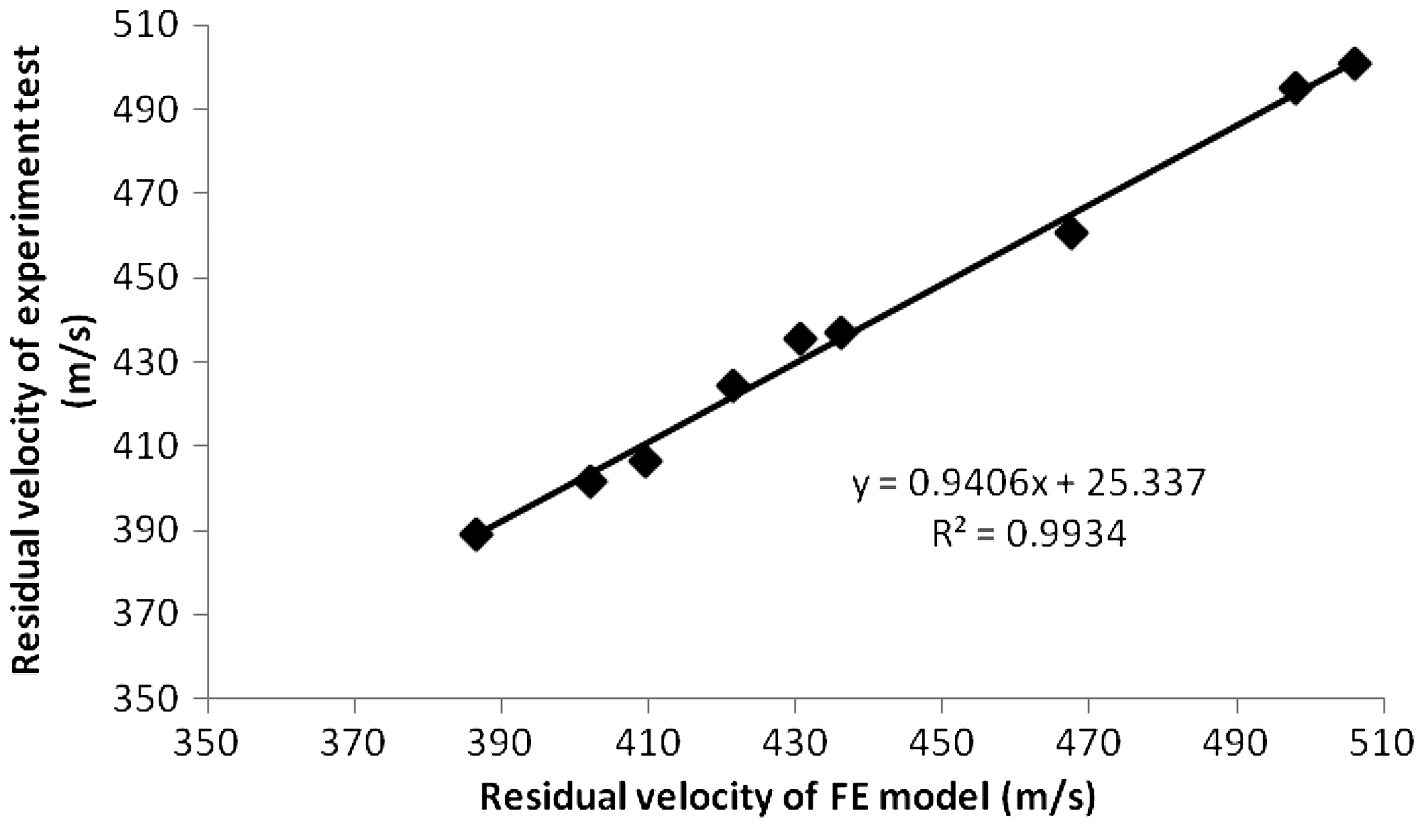
FE analysis on yarn–yarn friction
As has been mentioned in previous section, one of the objectives of this research is to investigate the influence of yarn–yarn friction on defining fabric penetration and energy absorption. The FE model created was used to predict fabric performance and stress distribution at different levels of yarn–-yarn friction, aiming to develop a comprehensive understanding of the working mechanism of yarn–yarn friction.
Effect of yarn–yarn friction on fabric ballistic performance
Figure 2 shows the predicted fabric energy absorption as a function of yarn–yarn coefficient of friction in the FE model. The curve increases from μ = 0, reaches a peak at μ = 0.4 and decreases from that point onwards. The energy absorption for μ = 0.4 was almost 1 J higher than that for μ = 0. Further increase in the coefficient led to a decrease in fabric energy absorption. The results display a similar trend to that of Zeng et al.'s [35] though the coefficient of friction giving the highest ballistic performance was found in that study to be at the lower value of 0.1. It is noteworthy that fabric penetration time gives a similar trend to the case of energy absorption. For example, the penetration moment for the case of μ = 0 is around 7.5 µs, while it takes around 10 µs to perforate the fabric for the case of μ = 0.4, which is shown in Figure 3. The penetration time decreases as the yarn–yarn frictional coefficient further increases.
Fabric energy absorption as a function of coefficient of yarn–yarn friction. Time history of projectile kinetic energy loss for fabrics with different yarn–yarn frictions.

This could be explained as follows: due to the lack of yarn–yarn friction, slippage occurs between the principal yarns and the secondary yarns. This leads the principal yarns to sustain most of the impact load, which is shown in Figure 4(a). As a result, the strain is more quickly accumulated and therefore early failure occurs in the primary yarns. For the case of μ = 0.4, the coupling caused by yarn–yarn friction prevents yarn slippage and enables the strain to be distributed to the secondary yarns, which is shown in Figure 4(b). This elongates the fabric engagement time with the projectile and delays yarn failure. The results corroborate the findings of Briscoe and Motamedi [36], whose observation from a high speed camera shows that fabric with low yarn–yarn friction tend to fail earlier than those with high friction. If the frictional force is too high, yarn mobility will be over-constrained. This leads the primary yarns to be damaged at an early stage, which is reinforced by the work of Zeng et al. [35] and Duan et al. [16]. In addition, this finding could also be supported by experimental data. A good example is the comparison of unidirectional fabric and woven fabric [37]. As the fibres are stuck together by binding materials in unidirectional fabric, it is reasonable to regard the frictional force as infinite in this type of structure. The results from ballistic test show that single-layer woven fabric absorbs around 12.7% more energy than the single-layer unidirectional fabric on the same areal density basis.
Single-layer fabric model upon ballistic impact at 6 µs. (a) μ = 0; (b) μ = 0.4.
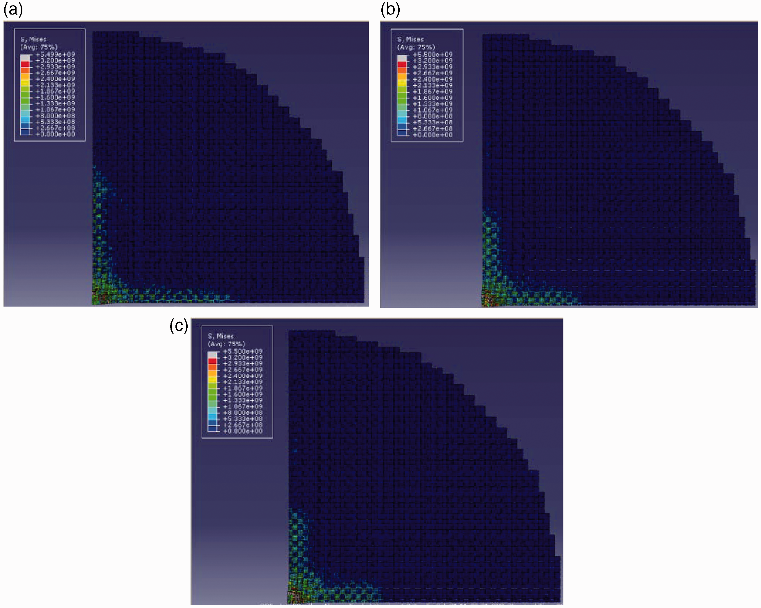
Stress distribution on the fabric model
Three cases, μ = 0, μ = 0.4 and μ = 0.8, were selected to represent different magnitude of yarn–yarn friction. Figure 5, Figures 6 and 7 reveal contour plots of stress distribution as time elapses. It can be seen that stress distribution is noticeably affected by yarn–yarn friction. For the case of μ = 0, the coloured area along the primary yarns gives a longer but narrow shape. The increase of yarn–yarn friction leads to a decrease of the length and an increase of the width for the coloured area. In addition, larger areas in the vicinity of the impact point are affected by the effect of friction. This indicates that although yarn–yarn friction impedes the stress propagation along the primary yarns, it enables more secondary yarns to get involved in energy dissipation. Nevertheless, contour plots observation fails to give a precise analysis of the stress distribution on the secondary yarns, which calls for further investigation. In this regard, Von Mises Stress is taken as an indicator of fabric stress distribution upon ballistic impact. Von Mises Stress σ' is a combination of the three primary stresses σx, σy, σz and the shear stress τxy, τyz, τxz. The value can be calculated using [38]:
Contour plots of stress distribution for fabrics at 2 µs after impact. (a) μ = 0; (b) μ = 0.4; (c) μ = 0.8. Contour plots of stress distribution for fabrics at 4 µs after impact. (a) μ = 0; (b) μ = 0.4; (c) μ = 0.8. Contour plots of stress distribution for fabrics at 6 µs after impact. (a) μ = 0; (b) μ = 0.4; (c) μ = 0.8.


In order to study the stress distribution along the primary and secondary yarns, a series of elements was selected, aiming at recording the area influenced by stress wave and value of stress at different timings. The elements used for analysis were shown as red lines in Figure 8.
Element selection on the fabric model.
Figure 9 reveals the stress distribution on the selected primary yarn at 2 µs, 4 µs and 6 µs. The figures bring out a number of features of general interest. The longitudinal wave velocity, which determines the capability of a fabric to dissipate energy, is found not to be influenced by yarn–yarn friction. The stress distribution, however, exhibits a significant difference. For fabric with high level of yarn–yarn friction, such as μ = 0.8, the area in the vicinity of the impact point exhibits higher values than the other two cases, which could possibly be associated with the constrained yarn mobility. The reduced yarn mobility may restrict the propagation of the stress wave and lead to a concentration of stress at the impact point. This consequently causes breakage at an early stage. For the case of μ = 0, although the increased yarn mobility enables the stress to be distributed far away from the impact point, yarn slippage causes more load to be sustained on the primary yarns and also leads to early failure.
Stress distribution on the primary yarn for fabrics with different yarn–yarn coefficients of friction. (a) 2 µs; (b) 4 µs; (c) 6 µs.
As can be seen in Figure 10, although yarn–yarn friction enables the secondary yarn to have more stress deposited on the area near the primary yarn, the areas affected for the three cases are almost identical as time elapses. It is believed that yarn–yarn friction increases the binding force between orthogonal yarns and therefore enhances their interplay. This being so, when a yarn is displaced, its orthogonal yarns are more likely to move due to the existence of binding force. It is clearly shown in this section that yarn–yarn friction plays an important role in stress distribution, which directly determines the energy absorption capability of a woven fabric. This may well be a finding of considerable importance in the design of ballistic fabric structure. If, by special weaving techniques or application of chemical-treatment, an improvement in fabric ballistic performance may be expected.
Stress distribution on the secondary yarn for fabrics with different yarn–yarn coefficients of friction. (a) 2 µs; (b) 4 µs; (c) 6 µs.
FE analysis on fabric failure mode
This section presents a detailed exploration of the failure mode of different layers in a panel subjected to ballistic impact. A FE model of an eight-layer woven fabric system was created to undertake this research. The performance of the first layer, second layer, fourth layer and eighth layer of fabrics were extracted from the model and put into comparison, aiming to develop a good understanding of the response of a panel to ballistic impact.
Stress distribution
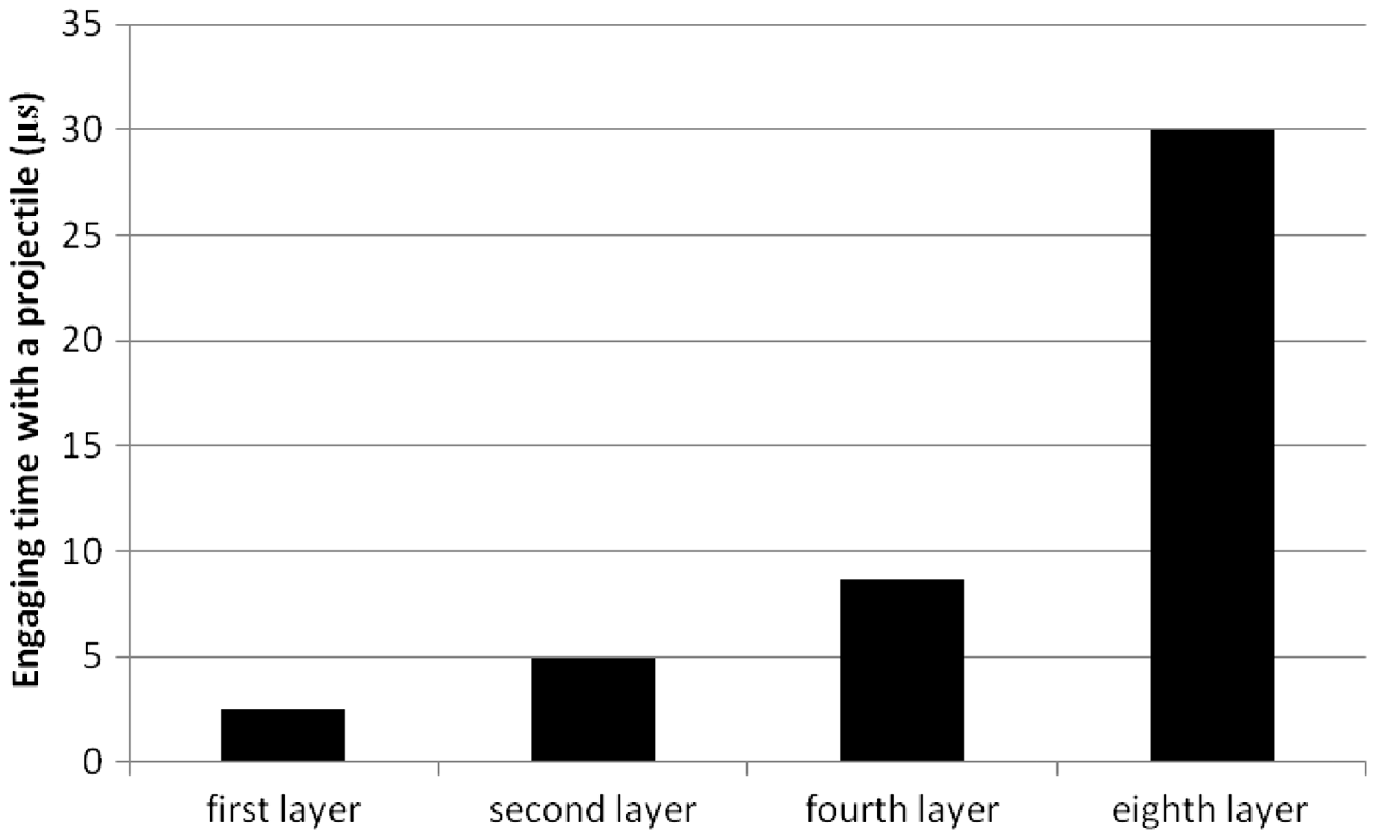
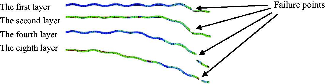
Figure 11 shows the contour plot of stress distribution for different layers of fabric. The stress is mainly stored in the vicinity of the impact point and on the primary yarns for fabrics near the impact face. For layers of fabric near the back face, stress is more evenly distributed over the whole fabric. It is noted that stress distribution has an effect on fabric engagement time with a projectile. In Figure 12, it has been determined that fabrics near the impact face tend to fail earlier than those near the back face. For instance, the first and second layers break within the first five µs, the eighth layer engages with the projectile for about 30 µs. As a result, the longer engagement time enables rear layers of fabric to have wider transverse deflection and to have a larger area of fabric get stressed at break, which increases its energy absorption.
Contour plots of stress distribution for different fabrics at break. (a) The first layer; (b) the second layer; (c) the fourth layer; (d) the eighth layer. Engagement time of different layers of fabric with a projectile.
Failure mode
As it has been established that the breaking time is closely associated with the performance and energy absorption of different layers of fabric in a panel,it is necessary to study the failure mode in a panel system. In FE simulation, failure occurs when the stress induced strain reaches material breaking strain. As mentioned in ‘FE models’ section, two failure criteria were set to define material failure in the FE model, namely tensile and shear failure. In this research, failed elements will be selected from the first, second, fourth and eighth layer and the magnitude of strain will be used as an indicator for the damage analysis on the fabric. Two strain components associated with ballistic impact will be considered, where ɛ11 is the strain in vertical direction and ɛ12 is the shear strain in vertical direction (see Figure 13). It is observed in the FE model that for fabrics near the impact face, such as the first and the second layer, failure tends to occur in the vicinity of the projectile edge. For the fabrics near the back face, however, failure is more likely to occur near the impact point, which is shown in Figure 14. This is because stress is more quickly concentrated on the front layers of fabric due to the reinforcement of their subsequent layers, causing the materials to be cut by the sharp edge of a projectile. Strain at the front layers of fabric tends to exceed the shear failure strain. As the projectile is not in direct contact with the rear layers of fabric, stress is transferred through the fabrics. This causes the material to be less subjected to shear failure. As a result, more stress is concentrated on the impact point, leading fabrics to fail in tension.
Stress components on an element. Schematic diagram of the failure point for each layer.
The failed elements were extracted from the model for strain analysis, the results of which are shown in Figure 15. As can be seen, for the first and second layers, ɛ13 gives extremely high negative values at break. This indicates that fabrics near the impact face are subjected to high shear strain, which play a dominant role in failure in a ballistic event. For middle layer fabrics, such as layer 4, and fabrics near the back face, such as layer 8, the shear strain peaks yield much lower value at break. Nevertheless, tensile strain ɛ11 is found to be higher for layer 4 and layer 8 than for layer 1 and layer 2 at break, which shows that failure is mainly caused by tensile stress along the yarn path. The FE predictions collaborate those of Chen et al., [39] who observed the failure mode of broken Kevlar fibres taken from fabrics near and away from the impact face, respectively. The failure ends of Kevlar fibre are shown in Figure 16. The shear-induced failure has a comparatively flat and cut-like end and tensile-induced failure has a fibrillation end, which could be seen on Kevlar fibres taken from a panel.
Strain components of failed elements for each layer. (a) ɛ12; (b) ɛ11. Broken Kevlar fibres taken from front and rear layers of fabric [38]. (a) Fibre from the front layer; (b) fibre from the rear layer.

Since both the FE prediction and SEM observation indicate that the front layers of fabric are more likely to be sheared to failure, and the rear layers tend to be stretched to failure, it suggested that shear resistant materials would be desirable for front layers and tensile resistant materials for rear layers. Improvement of ballistic panel performance could hopefully be achived by combining two types of materials.
Conclusions
The focus of this research has been to investigate the influence of yarn–yarn friction on fabric performance and the failure mode of fabrics in a panel system. Initial simulation showed that fabric energy absorption increases with yarn–yarn coefficient of friction from μ = 0 to μ = 0.4 and decreases thereafter. Contour plots of stress distribution show that the impact load is more likely to be concentrated on the primary yarns when yarn–yarn friction is low, which leads the primary yarns to be damaged at an early stage. Certain levels of yarn–yarn friction help to distribute the load to the secondary yarns and enable more materials to be involved in energy dissipation. If the friction is too high, the yarn movement is predicted to be over-constrained, decreasing fabric energy absorption and playing a negative role in ballistic performance. In a panel system, fabrics near the impact face tend to break in shear early, giving rise to an early failure timing. This causes small area of fabric get involved in energy dissipation. Fabrics near the back face fail in tension and have a longer engaging time with the projectile, leading stress to be distributed to a larger area. Soft body armour design guidelines were developed according to the FE predictions. The improvement in ballistic protection could be expected by using special techniques to improve yarn–yarn friction or hybridizing different materials in a panel system, leading to lightweight soft body armour.
Footnotes
Declaration of Conflicting Interests
The author(s) declared no potential conflicts of interest with respect to the research, authorship, and/or publication of this article.
Funding
The author(s) received no financial support for the research, authorship, and/or publication of this article.