



Abstract
The microstructures of injection-molded short fiber composites, involving fiber orientation and fiber concentration, strikingly influence flow behaviors and mechanical properties. Through the use of certain commercial software, reported numerical predictions of fiber orientation for the shell–core structure have been obtained to date. However, no work has been done on fiber concentration prediction available in processing simulations. In the theoretical field of suspension rheology, the suspension balance (SB) model has proven successful in capturing particle migration behavior under the simple Couette shear flow of “spherical” particle suspension, hence the attempt to verify the SB model applied in the “like-rod” suspensions. To predict flow-induced variations of fiber concentration, the SB model is implemented in 3-D-injection molding simulation with more general flows. It is remarkable for the shell–core structure is explored to reflect the relationship between fiber orientation and fiber concentration.
Introduction
In cost-effective manufacturing, short fiber reinforcement in thermoplastics has been widely used to enhance the mechanical performance and ameliorate the anisotropic deformation of a part for lightweight applications. Short fibers look more like powder, easily result in rotary diffusion, and quickly align along the flow direction. In practice, two processing microstructures are always concerned: the flow-induced fiber alignment is related to the fiber orientation distribution with the layered shell–core structure, while the flow-induced fiber migration corresponds to the gradient of the fiber concentration in the mold filling. 1 More recently, Kuhn et al. 2 used the direct fiber simulation and the microcomputed tomography (micro-CT) scan to discuss fiber matrix separation during compression molding of long fiber-reinforced thermoplastics. They observed that significant deviations in fiber concentration can lead to a decrease of mechanical properties, which could ultimately lead to component failure.
Numerical prediction of fiber orientation has become a standard calculation of the classic Folgar–Tucker model 3 in the commercial software of injection molding. Recently, two objective models were developed in order to obtain more accurate predictions: Anisotropic Rotary Diffusion and Reduced Strain Closure 4,5 (ARD-RSC) and Improved Anisotropic Rotary Diffusion and Retarding Principal Rate (iARD-RPR). 6,7 These orientation models have been applied as predictive engineering tools for injection-molded fiber thermoplastic composites.
Based on particle concentration of volume fraction, both the diffusive flux model 8,9 and the suspension balance (SB) model 10,11 are significant in simulating the migration of spherical particles immersed in a Newtonian fluid under the wide-gap Couette shear flow. From the concentrated suspension experiment on viscometric properties, the normal stress differences are discovered experimentally. 12,13 Correspondingly, the SB model can describe viscously generated normal stresses. However, the neglect of normal stress differences in the diffusion flux model is problematic, especially in regard to the nondiluted concentration limit.
Mondy et al. 14 reported some experimental data on fiber migration. They found that the steady-state concentration profile of fibers in the wide-gap Couette flow was relatively independent of the fiber aspect ratio and was close to that of spheres. Few works on the SB model have attempted to extend the rigid spherical particle suspensions to the rigid fiber (or cylindrical rod) suspensions.
Early, Toll and Andersson 15 observed a clear and systematic variation in fiber concentration within their molded parts. These data were recorded from the core region of the part to the shell layer. Their result indicated that the core concentration is obviously higher than the shell concentration. The fiber concentration distribution not only increases the complexity of flow behaviors but also affects the degree of mechanical properties. Unfortunately, state-of-the-art predictive engineering tools for injection-molded fiber composites have not provided “a function of flow-induced variation in fiber concentration” to date.
With concentrated fiber suspensions, we therefore aim to extend the original SB model of spherical particles to “rod-like particles.” Such a model is performed as a 3-D predictive engineering tool for injection molding with more general flows to predict fiber concentration. These predictions of fiber volume fraction are compared with related experimental data. In addition, we discuss the relationship between fiber orientation and fiber concentration for the shell–core structure in injection-molded fiber composites.
Theoretical background
Suspensions of solid particles dispersed in a liquid comprise complex fluids. The flow-induced particle migration indicates that changes in particle concentration are strongly driven by flow fields. For injection-molded fiber composites, the actual flow of the fibers dispersed in the polymer melt is transient, non-Newtonian, and nonisothermal, with frozen layers building up as the complex mixture flows through the mold cavity. The process is highly nonlinear, as the material properties are dependent upon the rheological and thermal conditions. Here, we summarize the theoretical equations involving the fluid mechanics, the flow-induced particle migration, and the SB model.
Governing equations of fluid mechanics
The governing equations of the fluid mechanics 16 which describe the transient and non-isothermal flow motion are as follows:




where ρ is the density;
Flow-induced particle migration
The migration of particles has occurred in bulk flows of non-Brownian suspension. Flow-induced particle migration, in explaining anomalies observed in a Couette viscometer, is a phenomenon resulting from the striking influence of the particle stresses. The diffusive flux model of Leighton and Acrivos 19 and the SB model of Nott and Brady 20 are frequently used in the literature on particle migration. In both models, the equations of motion based on particle concentration or volume fraction describe the motion of the particles in the suspensions.
The diffusive flux model is purely kinematic, in the sense that the flux of the particles in the suspension is in terms of the gradients of the particle concentration and the strain rate. This model consists of semi-empirical laws that describe particle migration based on irreversible particle collisions and does not account for the non-Newtonian viscosity of the particle fluid mixture. On the other hand, the SB model 10,11 is based on the two-phase flow theory; the particle flux is related to particle size, maximum particle concentration, and suspension viscosity, as well as a particular particle stress consisting of both shear and normal stress portions. Such a model relies on the non-Newtonian normal stress induced by shear, which gives rise to the particle migration.
Note that they differ substantially in their “derivation of particle flux.” Both models have been successful in capturing the particle migration behavior under the Couette flow. Viscously generated normal stresses in the SB model are crucial, since the significance of the normal stress differences measured by simulation and experiment are useful viscometric properties of the suspension. 12,13 However, neglecting the normal stress differences in the diffusion flux model is problematic. For this reason, we adopted the SB model to predict fiber concentration in general flow simulations.
The SB model
Description of the flow in a two-phase suspension requires mass and momentum balances for the bulk suspension and one of the components. Following previous studies, Nott and Brady 20 and Morris and Boulay 10,11 considered the balance equations of the bulk mixture and particle phase to develop the SB model for the suspensions flow of rigid spherical particles in a Newtonian fluid. The particle phase is approximated as a pseudo-continuum. The dominant interaction between the particles involves hydrodynamics, viscous, and non-Brownian forces without external field, except for gravity.
The conservation equation of particle-phase mass balance 10 may be expressed as follows:


where φ is the particle volume fraction, 〈
In assuming the Stoke flow, the particle flux

where a is the particle radius, ηf is the viscosity of the suspending fluid, f(φ) is termed the sedimentation function, and Σ p is the particle stress.
The sedimentation function is described in Richardson and Zaki 21 :

where φm is the maximum volume fraction and φm = 0.63 is for the random close packing monodisperse spheres; the power index, n, is given as n = 2 − 4.
The particle stress tensor Σ p is a symmetric matrix containing both shear and normal stress portions, as suggested by Morris and Boulay 10,11 for shear flows:

where ηp and ηn are the particle stress contributors to the shear stress viscosity and the normal stress viscosity made dimensionless with ηf, respectively.
Both ηp and ηn are given in dimensionless volume fraction


where two factors, Ks = 0.1 and Kn = 0.75, are fit to match the experimental data of the wide-gap Couette flow. 10 Note that the relative viscosity is defined as follows:

The anisotropic tensor

where the tensor
Physically, the particle stress tensor of equation (9) implies that all normal stresses are negative, and the shear flow results in a positive suspension pressure. It is clear that the anisotropic particle stress tensor’s three diagonal components are given in terms of this modeling by the following equations:



Thus, the first and second normal stress differences (N1 and N2 ) and suspension pressure (Π) are obtained as follows:



Validation of fiber concentration prediction in Couette flow
Mondy et al. 14 made an early report on some experimental data on the migration of fibers. They found that the steady-state concentration profile of fiber in the wide-gap Couette flow confined between two concentric, rotating cylinders was relatively independent of the fiber aspect ratio and was close to that of spheres. Figure 1 shows a schematic depiction of the steady-state Couette shear flow and the cylindrical coordinate system. In this flow, the azimuthal angle θ coordinate and the radial coordinate r are the flow and gradient directions, respectively. Below, we simplified the SB model to derive an analytic equation verified with the experimental data of Mondy et al. 14
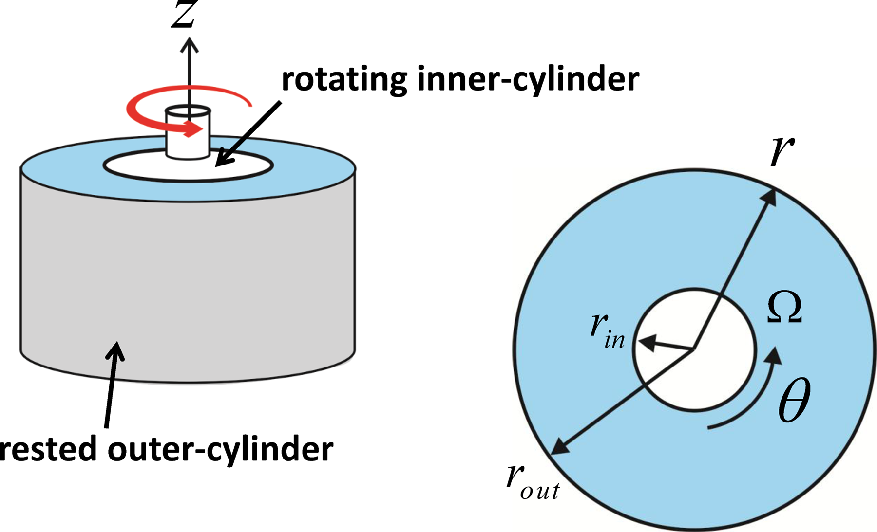
Illustration of a simple wide-gap Couette flow confined between two concentric cylinders.
According to previous work of Morris and Boulay 10 for the flow approaching a steady-state in radial direction, the momentum balance of particle stress reduces to


In terms of the first normal stress difference, equation (21) is given by:

According to equations (14) to (16), the θ direction and the r direction are marked as the flow index 1 and the gradient index 2, respectively,

In setting a new variable,

where C1 is a constant of integration.
The shear stress balance in the rθ plane is expressed as follows:

Two terms of equation (25) can be combined as

which is integrated to yield

where C2 is a constant of integration.
In addition, the Newtonian shear viscosity ηs(φ) is defined as follows:

By combining equations (27) and (28), the shear rate

which is substituted in equation (24) to derive the following equation:

where C is a constant determined by the bulk concentration ϕbulk at the wide-gap center and the anisotropic tensor component λ2.
Experimental fiber concentration profiles φ(r) of Mondy et al.
14
involve two bulk (or average) volume fractions, φbulk = 0.3 and 0.4, for a nylon rod with aspect ratios ranging from 2 to 18 immersed in Newtonian oil. In the Couette shear flow, the resting outer cylinder radius rin is 2.38 mm and the rotating inner cylinder radius rout is 0.64 mm, while the rotation rate Ω of the inner cylinder varied between 10 and 117 r/min. Figure 2 shows the fiber concentration profiles
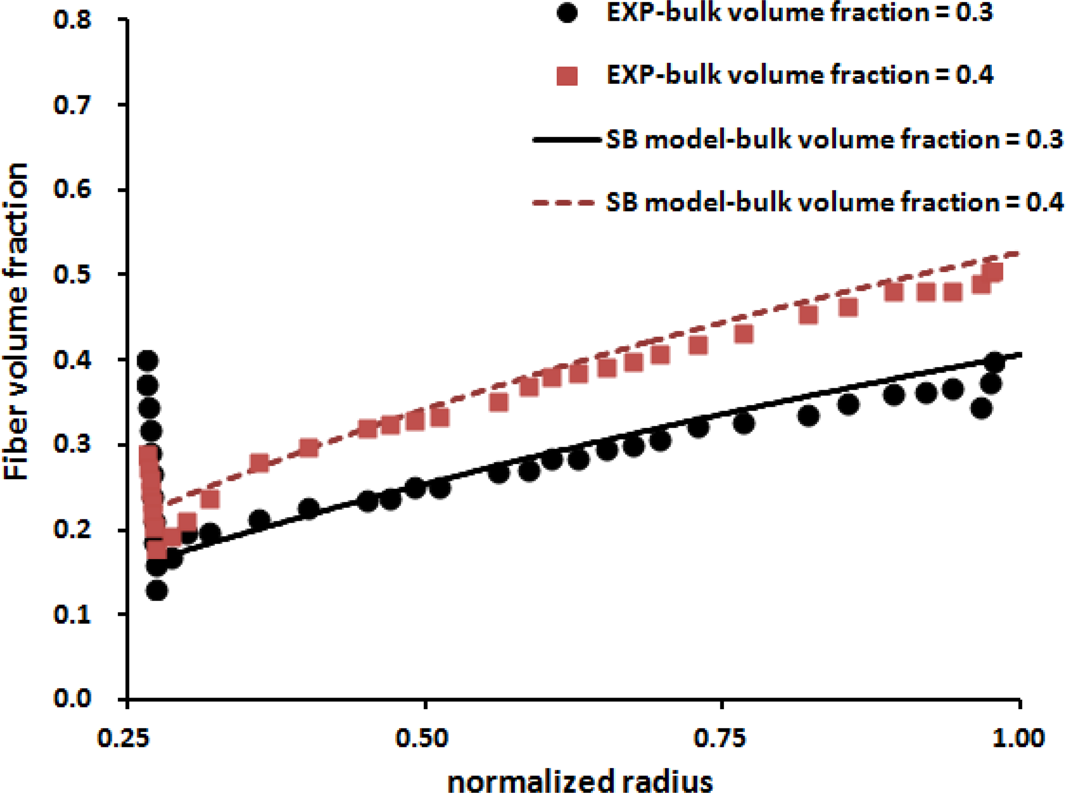
Fiber concentration distribution of volume fraction through the normalized radius for various bulk volume fractions (0.3 and 0.4) in the steady-state Couette shear flow.
Giving different radiuses and bulk volume fractions to the simple form of equation (30) attached with equations (10) to (12) for the SB model, it becomes a nonlinear equation of variable φ that must be numerically solved with the tried parameter λ2 = 1.8 and the maximum volume fraction of φm = 0.63. The constant C is determined by φbulk given at the wide-gap center, 0.5(rin + rout). Thus, we obtained the predicted fiber concentration in the steady-state shear flow. Overall, the agreement between the experiments and predictions is fairly good, except for unexpectedly higher volume fractions near the wall. Therefore, the SB model is available for predicting fiber concentration in shear. In the next section, we will extend such a model to be applied to more general flows.
Prediction of fiber concentration distribution in injection molding
To date, the SB model has been implemented in commercial injection molding simulation software, Moldex3D (CoreTech System Co., Ltd., Chupei, Taiwan). In Moldex3D, 3-D numerical techniques of finite volume method (3-D-FVM) 22 are adopted to solve the above equations with robustness and efficiency in a complex 3-D geometry. To reduce computational resources, a decoupled approach has been applied in which the fluid flow problem is first solved, and the resulting velocity field is used to compute the particle concentration of the SB model.
Recently, Vélez-García et al. 23,24 investigated the different measurement methods to derive experimental data on fiber orientation and fiber concentration for polybutylene terephthalate (PBT) resin containing 30% by weight of short glass fibers (30 wt% SGF/PBT). These measurements, based on the method of ellipses (MoE) for analyzing scanning electron microscopy (SEM) images of fibers, 25 contain the Bay–Tucker standard approach, 25 the Leeds analyzer (LA), 26 and the Vélez-García–Wapperom–Baird (VWB) method. 23,24 In MoE, elliptical footprints of a fiber in a polished cross section are used to reconstruct the three-dimensional orientation of a fiber. The interested reader is referred to relevant information available elsewhere 23,24 and so the details are not repeated here. Our primary objective is to verify fiber concentration by using the SB model with the significant experimental data of Vélez-García et al. 23,24
As stated in Vélez-García’s PhD dissertation,
24
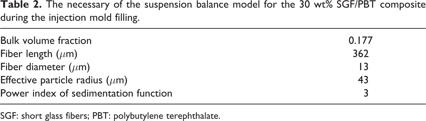
the fiber composites of 30 wt% SGF/PBT (Valox 420 [SABIC Innovative Plastics]) were used. Note that the bulk fiber concentration is fiber weight percentage of 30 wt% or fiber volume fraction of φbulk = 0.177. The number-average fiber length and fiber diameter are lf=362 μm and df=13 μm, respectively; the fiber aspect ratio is about ar=lf/df=28. Such a composite is a concentrated suspension since
Figure 3 shows the thin center-gated disk of interest in injection molding as 52 mm in radius and 1.38 mm thickness. There were four measuring regions considered in the disk: 1, 10, 40, and 90% of the flow length along the radius direction, related to the gate, entry, lubrication, and frontal regions, respectively. The mold and melting temperatures were set at 90 and 260°C, respectively. The filling time was 2.23 s, and the volume flow rate was about 11.8 cc/s. Details of injection molding are available elsewhere. 23,24
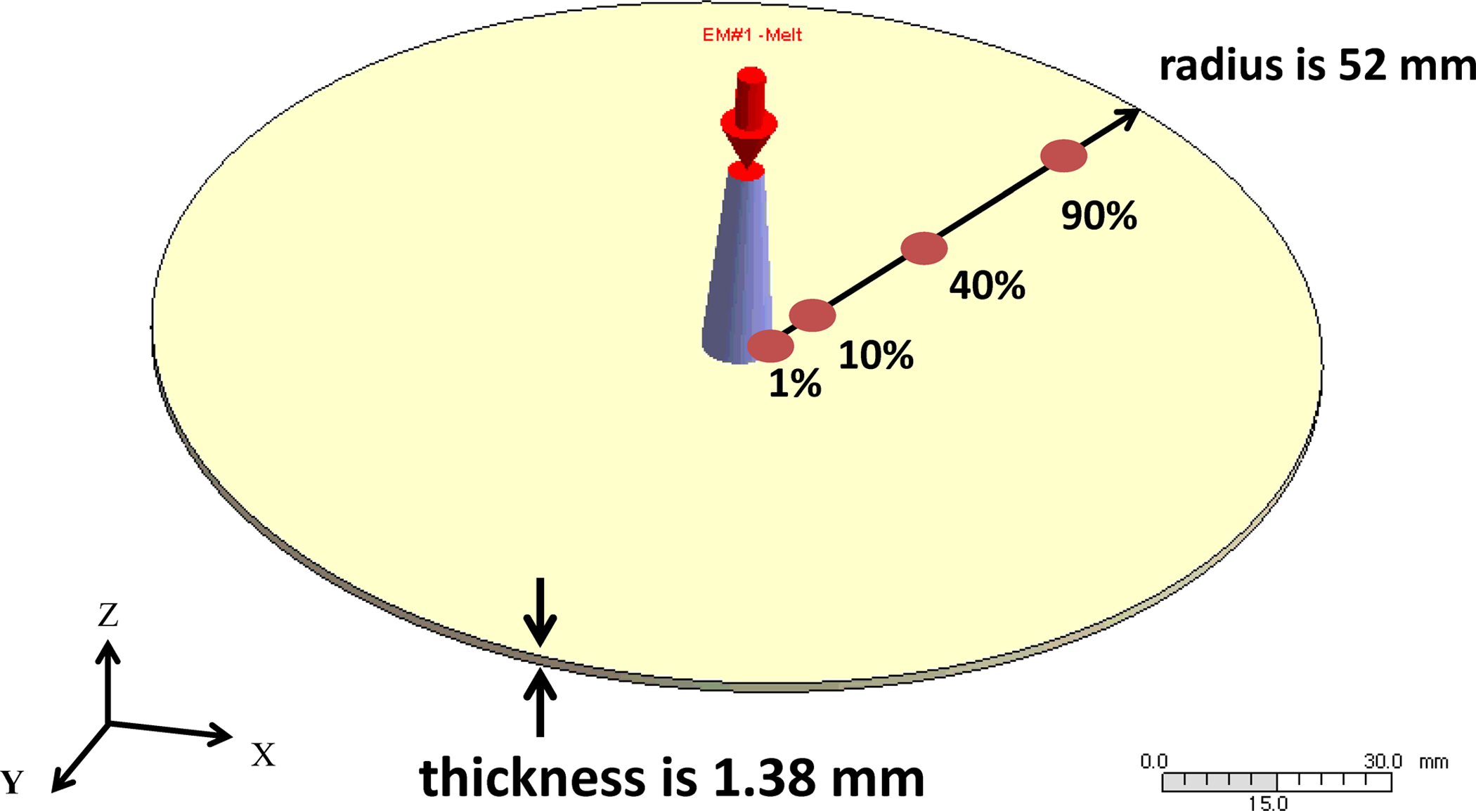
Illustration of the center-gated plaque (52 mm radius and 1.38 mm thick).
In the present work, we utilized Moldex3D to perform the 3-D injection molding simulation of the center-gated disk. The injection molding conditions are addressed in Table 1. The SB model has been incorporated in Moldex3D. Referring to the simulation of fiber Suspension flow with shear-induced migration of Fan et al., 27 the effective particle radius ae is given to the SB model of equation (7),

where a fiber is modeled as a rod with its diameter df and length lf . In addition, the power index sedimentation function of equation (8), n =3, is set. Table 2 lists the necessary the SB model.
Processing conditions of injection mold filling for the 30 wt% SGF/PBT composite.
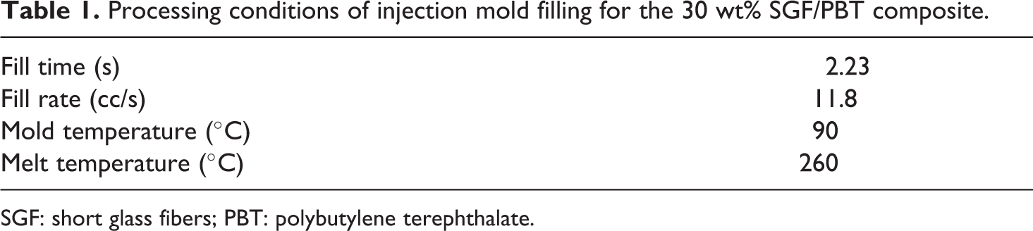
SGF: short glass fibers; PBT: polybutylene terephthalate.
The necessary of the suspension balance model for the 30 wt% SGF/PBT composite during the injection mold filling.
SGF: short glass fibers; PBT: polybutylene terephthalate.
From the Moldexe3D simulation, Figures 4 to 7 show the predictions of the fiber concentration distribution located at 1, 10, 40, and 90% of flow length, respectively. The experimental data are referred to in Vélez-García’s PhD dissertation. 24 All of the data for fiber volume fraction against the normalized thickness are represented. Overall, the numerically predicted fiber concentrations are close to the experimental data. No work or predictive engineering tool has been previously done on fiber concentration prediction for injection-molded fiber composites. These fiber concentration predictions are first provided in the practical injection molding simulation.
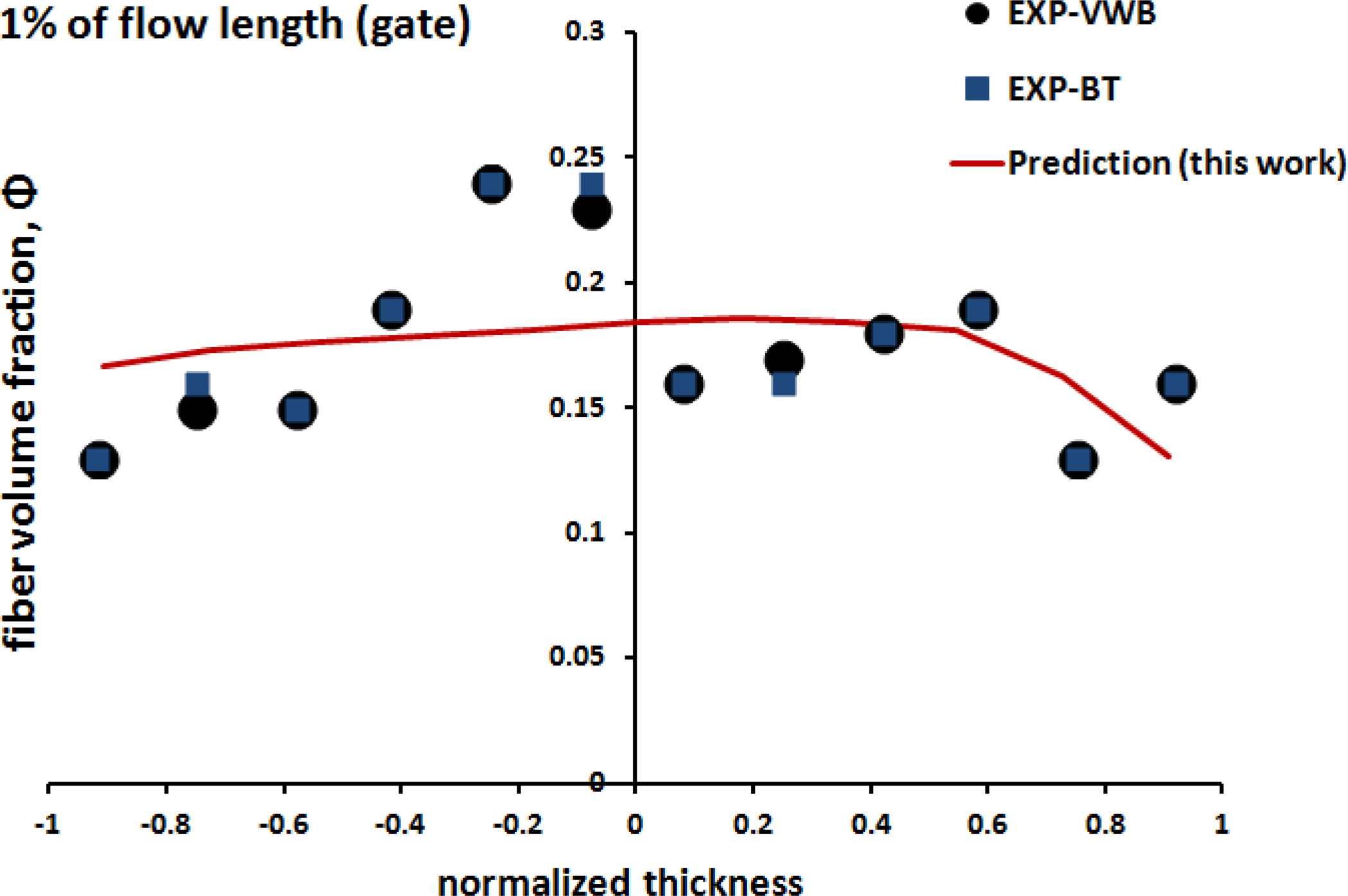
The fiber concentration distribution of volume fraction through the normalized thickness at the 1% (gate region) of the flow length for the 30 wt% SGF/PBT composite. SGF: short glass fibers; PBT: polybutylene terephthalate.
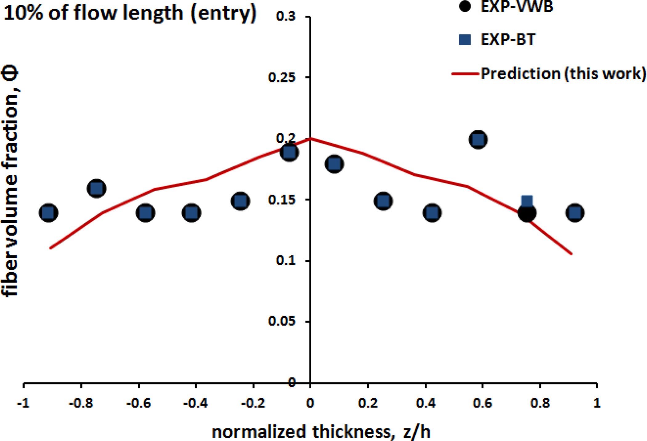
The fiber concentration distribution of volume fraction through the normalized thickness at the 10% (entry region) of the flow length for the 30 wt% SGF/PBT composite. SGF: short glass fibers; PBT: polybutylene terephthalate.
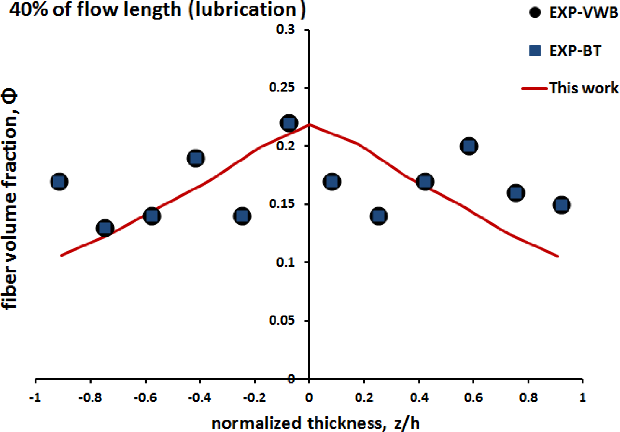
The fiber concentration distribution of volume fraction through the normalized thickness at the 40% (lubrication region) of the flow length for the 30 wt% SGF/PBT composite. SGF: short glass fibers; PBT: polybutylene terephthalate.
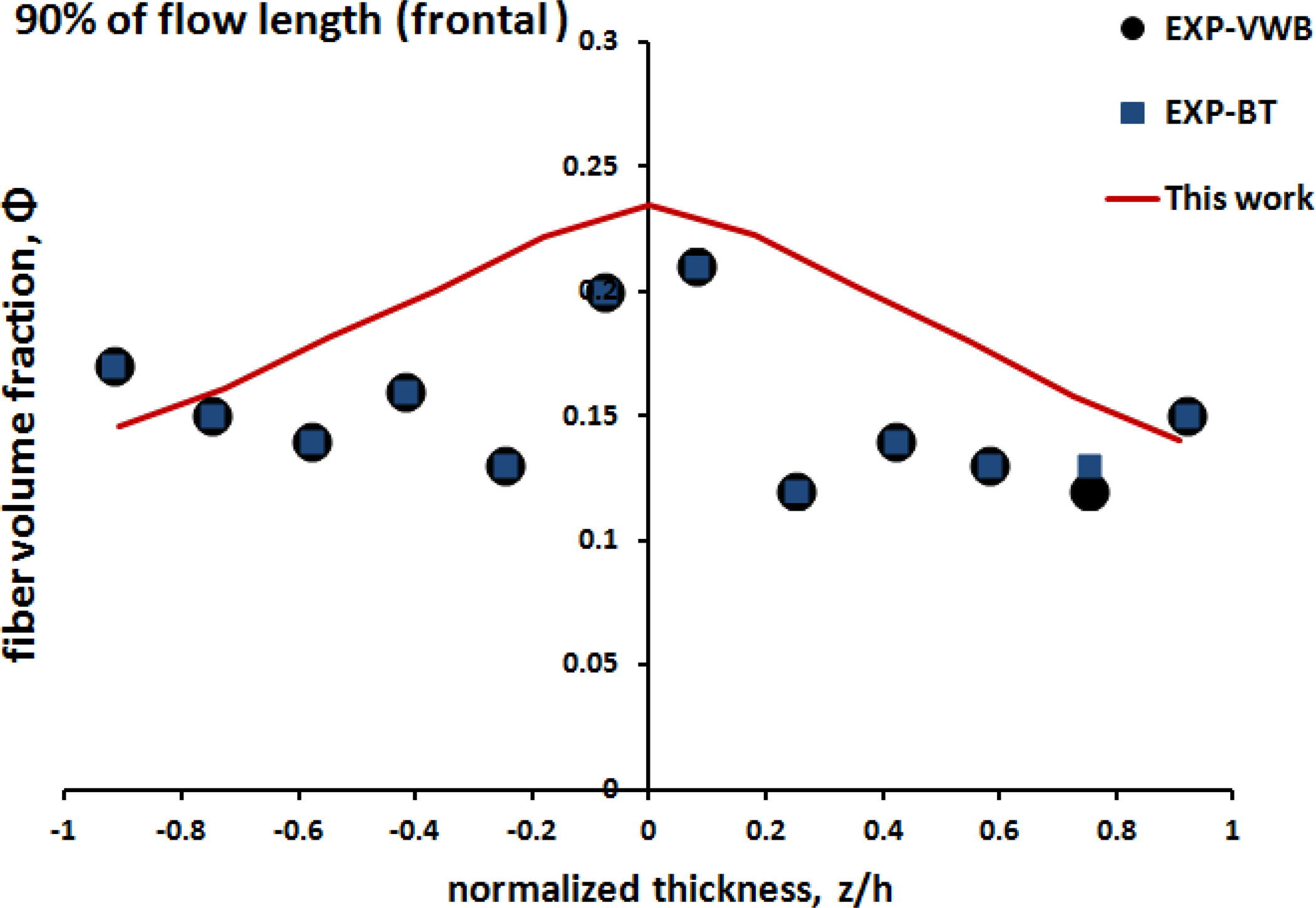
The fiber concentration distribution of volume fraction through the normalized thickness at the 90% (frontal region) of the flow length for the 30 wt% SGF/PBT composite. SGF: short glass fibers; PBT: polybutylene terephthalate.
In particular, at the 40%of the flow length located near a middle point along the radial direction, there is an obvious minimum concentration (φ=0.12 or 25.4 wt%) in the shell layers near the wall due to a high shear rate and a maximum concentration (φ=0.21 or 35.3 wt%) at the central core region due to a low shear rate. The shear rate profile at the 40% of the flow length is presented in Figure 8. This nonuniform concentration distribution or fiber concentration gradient is the representation of the shear-induced fiber migration.
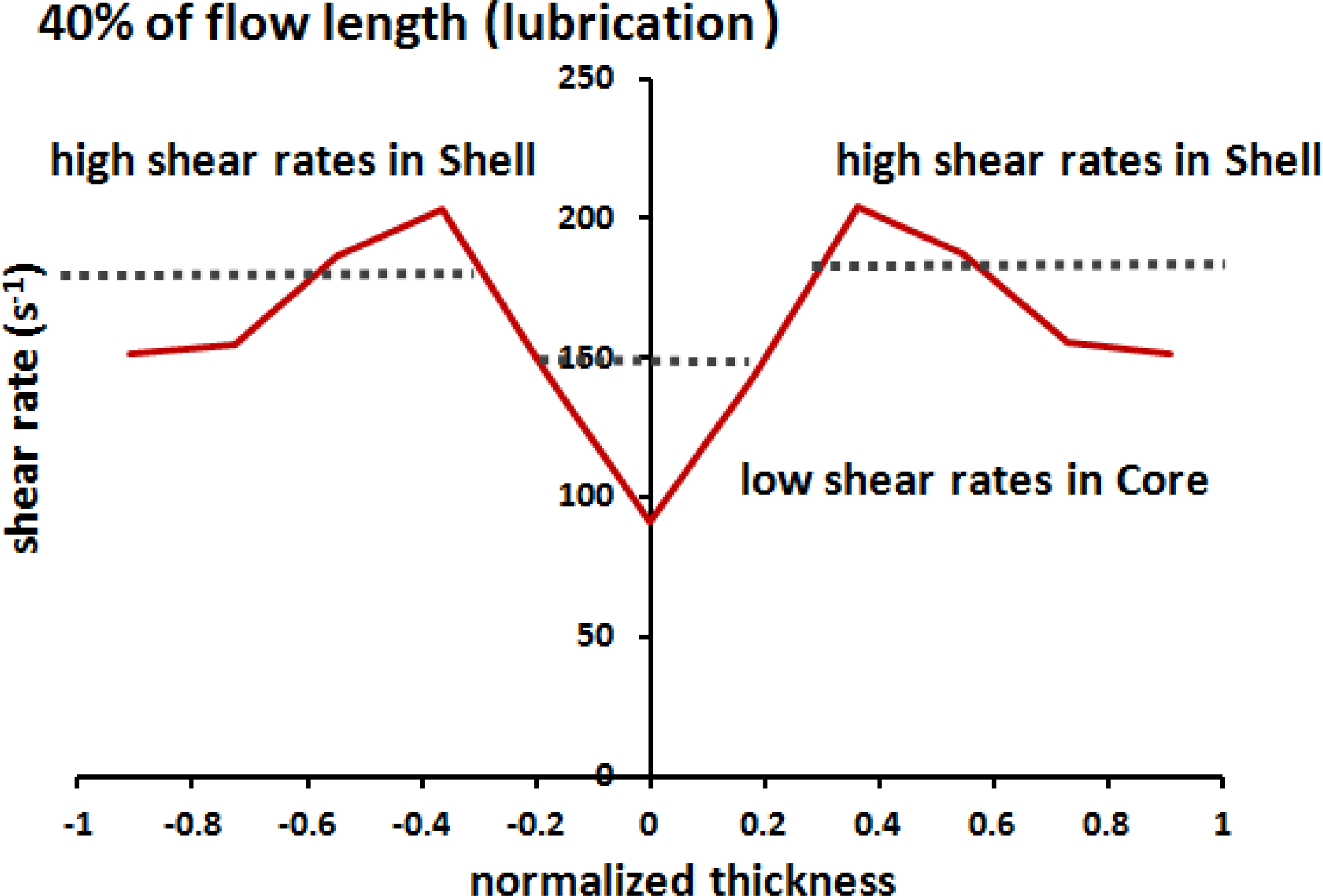
The predictive shear rate profile through the normalized thickness at the 40% (lubrication region) of the flow length for the 30 wt% SGF/PBT composite. SGF: short glass fibers; PBT: polybutylene terephthalate.
Previously, Toll and Andersson 15 observed a clear and systematic variation in fiber content within their molded parts. Both burn-off and image analysis measurements were performed. These data were recorded in the central region of the part, away from the edges. Using a molding compound with a nominal fiber weight percentage of 30 wt%, the core had higher concentration of 36 wt%, while the shell had lower concentration of 28 wt%. Thus, our predicted result is in good agreement with the experimental observation.
Moreover, Figure 9 shows the flow direction fiber orientation component distribution predicted by the iARD-RPR fiber orientation model incorporated in Moldex3D. 28 Three parameters are given: CI = 0.008, CM = 0.1, and α = 0.9. The filled symbols are the experimental data of Vélez-García’s PhD dissertation. 24 The orientation distribution exhibits a noticeable feature, the core–shell structure. The fibers found in the shell region near the cavity are strongly aligned with the flow direction, as opposed to the others found in the core region near the cavity center, which are transverse to the flow. We found the shell–core fiber orientation structure with respect to fiber concentration. Obviously, the core region exhibits the lower orientation and higher concentration, while the shell layers possess the higher orientation and lower concentration. For an overall assessment of the prediction accuracy, the thickness-averaged value of predictive and experimental data includes the flow orientation component <A11 > and the fiber volume fraction <φ>, as listed in Table 3. Thus, the relative error of the predictions is below 10%, with a comparison of the experimental data.
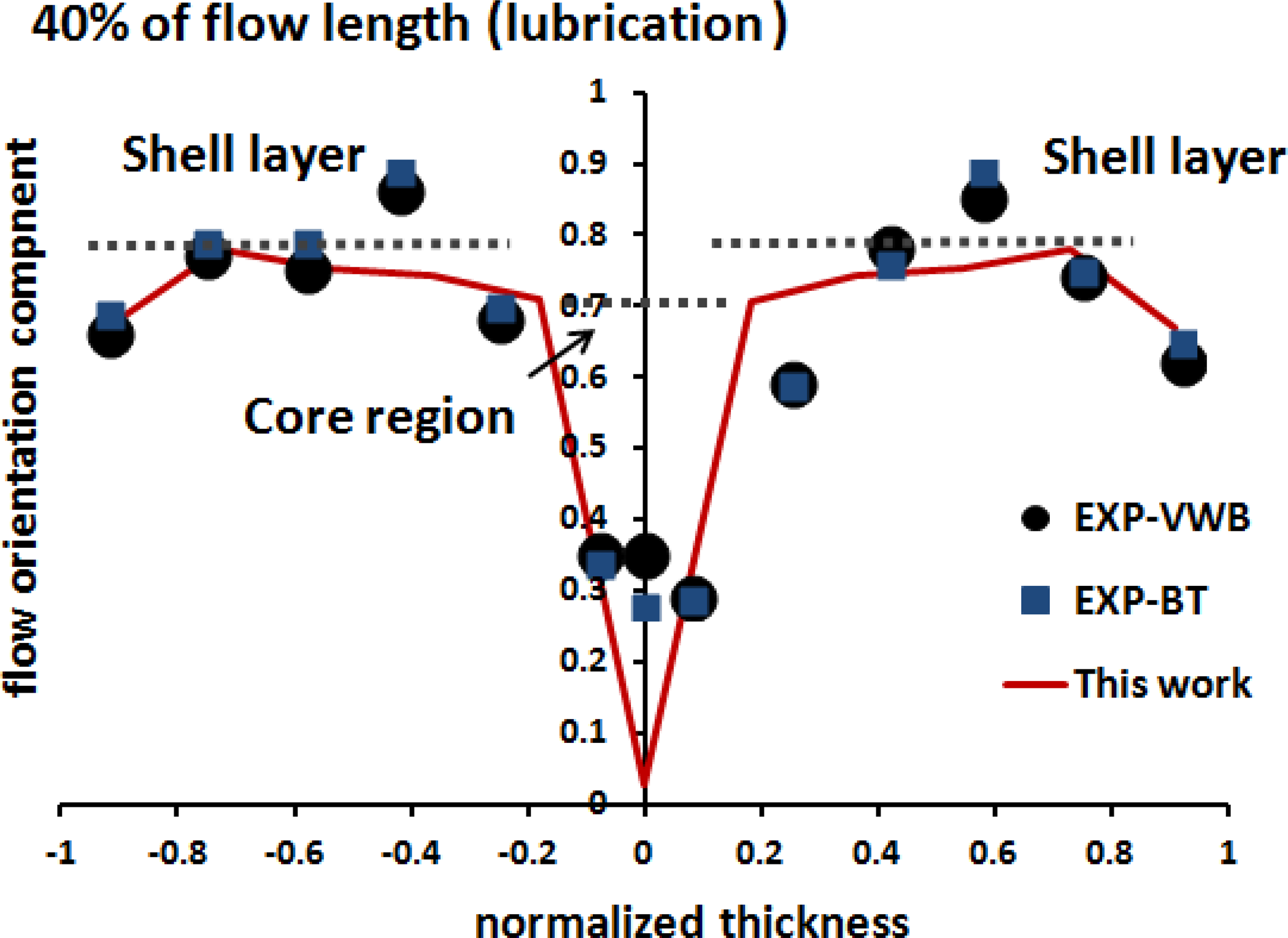
The predicted curves and experimental data of flow-direction orientation tensor component distributions through the normalized thickness at the 40% (lubrication region) of the radius direction flow length for the 30 wt% SGF/PBT composite. SGF: short glass fibers; PBT: polybutylene terephthalate.
The thickness-averaged predictive and experimental data of the flow orientation component <A 11> and fiber volume fraction <φ> at the 40% (lubrication region) of the flow length the for the 30 wt% SGF/PBT composite.a
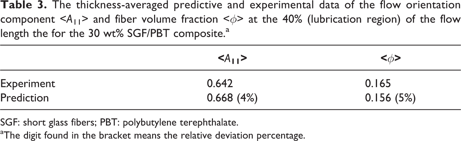
SGF: short glass fibers; PBT: polybutylene terephthalate.
aThe digit found in the bracket means the relative deviation percentage.
Conclusion
Our ultimate objective was to perform numerical prediction of fiber concentration in injection molding of fiber composites. It is significant that the SB model of the flow-induced particle migration has been extended to more general injection molding flows of non-Newtonian fluids for fiber (rigid cylindrical rod) suspensions, rather than for prior rigid spherical particles in a Newtonian fluid under the wide-gap Couette shear flow. Consequently, such a model has been demonstrated as able to predict fiber concentration in processing simulations. On the other hand, the shell–core fiber orientation structure can also be obtained from the simulation. Remarkably, the core region exhibits the lower flow orientation and higher volume fraction, while the shell layers possess the higher flow orientation and lower volume fraction. Overall, the predictions of fiber orientation and fiber concentration were in good agreement with related experimental data. In the future, we will consider the influence of fiber concentration on complex flow behaviors, mechanical properties, and anisotropic shrinkage/warpage deformation; this will be most valuable for fiber-reinforced thermoplastic industrial fabrication.
Footnotes
Declaration of Conflicting Interests
The author(s) declared no potential conflict of interest with respect to the research, authorship, and/or publication of this article.
Funding
The author(s) received no financial support for the research, authorship, and/or publication of this article.