
Abstract
In this research work, the possibility of defect detection in wood–plastic composites (WPCs) by shearography method has been assessed. Shearography is one of the practical nondestructive test methods that has been commonly used for detecting defects in polymer-based composites. In this experimental work, first, a defect (hole) was intentionally drilled on one side of the extruded WPC and then the shearography test and analysis was performed on it. This preliminary step was performed to evaluate the application of the test and calibration. Subsequently, the injection-molded WPCs with different volume fraction of wood content were assessed via shearography test for detection of the probable defects in their structures. The results indicated that shearography method can be effectively used for defect revelation in wood–plastic composites.
Introduction
Using nondestructive tests (NDTs) to discover defects in material structure has always been attractive for researchers and manufacturers. 1 –3 Digital technology of shearography records the media under study via video sensors and processes the captured images data. This method has some advantages over the other available shearography techniques such as photographic and thermoplastic recording including reconstruction of fringe pattern without relying on Fourier filtering, real-time measurement and inspection, and also avoiding the usage of consumable needs. 4,5 Hung et al. 6 used shearography as a noncontacting optical strain rosette for determining residual stresses in plastic and composite materials. Development of shearography, as an NDT technique, leads to the use of holography-stressing methods for under study specimens loading. 7 Several different ways such as pressure, vacuum, thermal, and acoustical, and mechanical excitations were developed for creating reasonable rigid body motion in this method. 4 Some important applications of this NDT method could be crack detection, revealing several areas of separation due to fatigue damage, and inspection of adhesive-bonding composite assemblies. 8 –11 For example, inspection of tires in rubber industry or confirming the healthy structures of aircraft structures in aerospace industry are some practical examples of shearography. 4
Wood–plastic composites (WPCs) are one of the most applicable composites that are widely growing in various fields. Thermoplastics such as polyethylene, polypropylene, and polyvinyl chloride can be used as a matrix in these composites. 12,13 The broad range of its applications has been reported in publications which are mainly aimed at building sectors. 14
The principle methods for fabrication of WPCs are extrusion and injection molding. Extrusion, during which the polymer and wood components are fed via a hopper with additives (either premixed or separate), then melted, and shaped using a die, is the most common manufacturing method. 12 –14 The injection molding method is also used to shape premixed wood and plastic component (granules) to fabricate parts that cannot be produced via extrusion. 15
Composite materials consist of two or more elements, one which, the fiber, is dispersed in continuous matrix phase. The two elements work together to form unique material properties. The quality of adhesion between the fiber and matrix is the most important factor for achieving the desired properties. A poor quality of adhesion may lead to the presence of defects at the wood–polymer matrix interface, which is the main source of weakness. Therefore, using new and practicable methods for inspection of composites in order to discover defects in their structure seems to be highly important.
In this research work, shearography method was employed to inspect the structure of WPCs. The first step was to evaluate the feasibility of performing shearography as an NDT method for WPCs through intentional defect creation on it. After proving this claim, the effect of various wood contents in WPCs was also examined by this method for detection of existing probable defects in their structures. It is noteworthy that there is no previous report on using the shearography for inspection of WPC structure.
Materials and methods
As the polymeric matrix, high-density polyethylene (HDPE), produced by Arak Petrochemical Complex (Iran), was used. Sieved oak wood saw dust, with particle sizes up to 30–40 mesh, was used as the wood component. Three fractions of wood contents of 10, 25, and 40 wt% (Figure 1(b) to (d)) were used to fabricate the WPCs via injection molding process. Also, one composition of WPC with 60 wt% wood content and polyethylene (HDPE) as a matrix was fabricated via extrusion process. This specimen was used as a sound product with high content of wood, which could not be produced utilizing injection molding process, was intentionally drilled for evaluation of shearography possibility on WPC (Figure 1(a)).
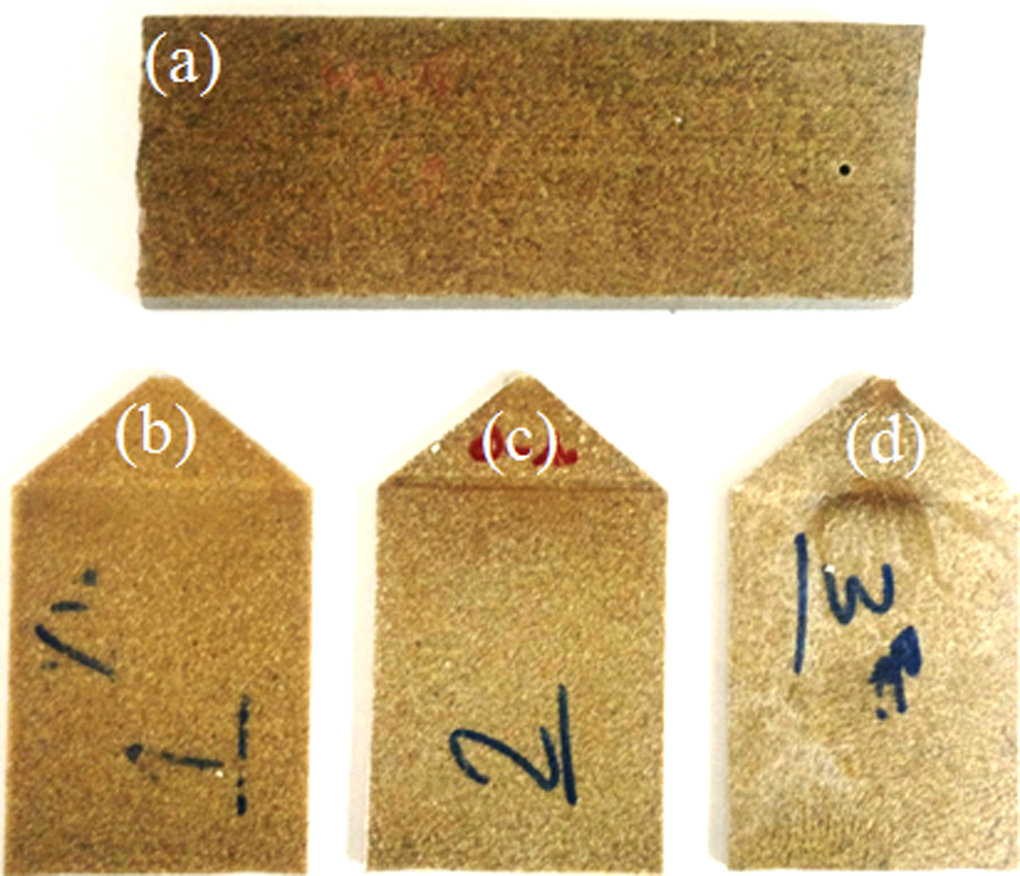
Specimens fabricated via (a) extrusion containing 60 wt% wood particles and (b) to (d) injection molding containing 10, 25, and 40 wt% wood particles, respectively.
Figure 2 shows the setup utilized for shearography of the specimens that consists of an antivibration table, an Instron tensile test machine (Norwood, Massachusetts) to constrain the specimens, a 10 mV laser light source with a wave length of 632.8 nm, two mirrors with aluminum (Al) coating, 1 in. in diameter and 9 mm in thickness, for bilateral radiation, two mirrors with Al coating, 2 in. in diameter and 4.5 mm in thickness, for using in Michelson interrupter, two cave-flat lens with 0.5 in. in diameter to scatter the light and light beam separator with dimensions of 20 × 20 × 20 mm. Also, a charge-coupled device camera (ARTRAY 320P (Camarillo, California)) was used for capturing and recording the high-quality images. Thermal stressing by heat radiation was used for creation of strain in the specimens. To improve the contrast in the shearography fringe pattern, the surface of the specimens was painted with white spray paint before test.
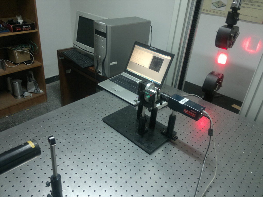
The setup for shearography test used in this research work.
The procedure of examination is detailed as follows: initially, it is better to cover the specimen’s surface with white spray to get the high-quality images. Then, the specimens were gripped by one or two jaws of the tensile machine. In the next step, thermal loading through fluorescent lamp radiation was applied on the constrained specimen leading to create small strains on the surface of them. The above-mentioned optical equipments (Michelson interrupter etc) capture the speckle pattern images of specimen’s surface before and after loading, and relevant codes were used to extract the two images and form the parallel regular dark and white lines pattern. If there is a defect in the specimen, the separated area deviates this pattern. Figure 3 shows the schematic of the experiments prepared for shearography of the specimens. In this research, three images were captured from the specimens during the unloading to further confirm the obtained results.
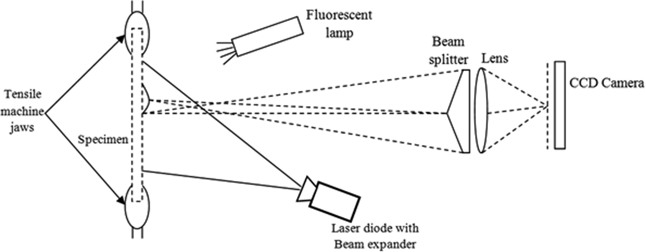
Schematic of loading condition.
In this experiment, the constraining condition was fixed at two sides for all specimens, but for the injection-molded specimen with 40 wt% wood content, one-side fixed condition was also examined.
Result and discussion
As mentioned above, first; the specimen with 60 wt% wood content fabricated via extrusion process was used for the feasibility assessment of defect detection via shearography in WPCs. Figure 4(a) presents the image produced in shearography for this specimen. The figure indicates no defect in the specimen designated by the formation of parallel dark lines in the filtered image. However, to insure the reliability of the results, a hole with 2 mm in diameter was drilled on one side of the specimen and shearography process was then carried out again. Figure 4(b) indicates the obtained image showing the formation of fringe pattern, which indicates the presence of defect (the drilled hole) in the specimen. Based on the investigation carried out by Liu et al. 9 on the feasibility of shearography for different materials including HDPE, it can be deduced that wood powder impose no limitation on using this NDT method for WPC inspection.
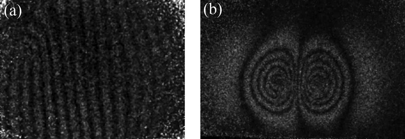
(a) Parallel dark line resulted from the shearography of the extruded composite and (b) fringe pattern in dark lines in drilled specimen.
In the next step, shearography was carried on the injection-molded specimens to discover the probable defects. Figure 5 shows the results of shearography at 1, 2, 3, and 4 s after unloading the injection-molded specimen with 10 wt% wood powder (Figure 1(b)) indicating the absence of defects. As seen in these images, the vertical dark lines remain parallel at different times of unloading and only get closer to each other without any deviation. The low volume fraction of the wood (10%) in the sample could be the reason of a healthy sample due to (1) facilitating the material flow as a result of low viscosity of composite during process and (2) good dispersion of the wood in the polymer matrix.
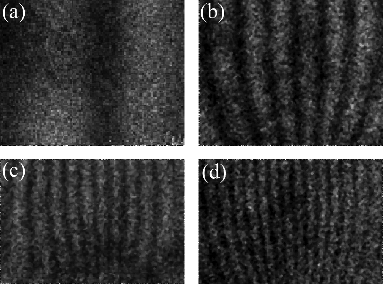
(a) to (d) Parallel dark lines resulted from the shearography of the injection-molded specimens with 10 wt% wood content 1–4 s after unloading, respectively.
Figure 6 shows the result of shearography performed on the specimen (Figure 1(c)) containing a higher amount of wood particles (25 wt%). The figures show the obtained images at 2, 4, and 6 s after unloading.
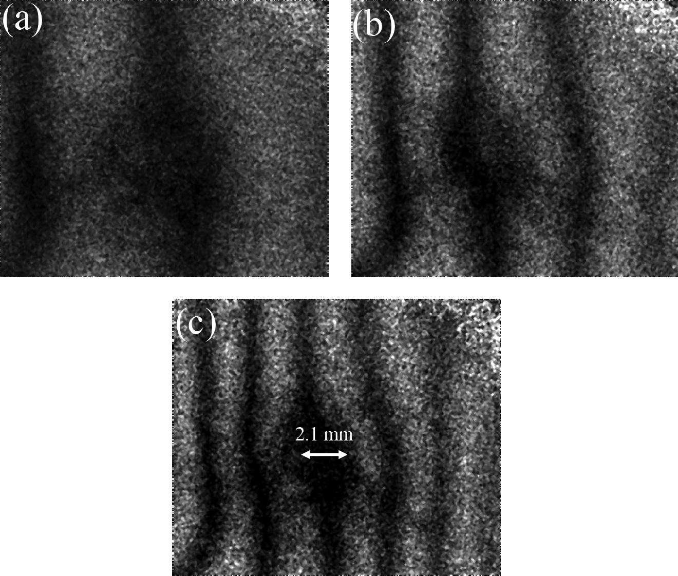
(a) to (c) Dark line patterns resulted from the shearography test of the injection-molded composite with 25 wt % wood content 2, 4, and 6 s after unloading, respectively.
The results indicate that the numbers of vertical dark lines are added with time increase. However, a small deviation of vertical dark lines is observed with an estimated length of up to 2 mm, which could be due to the agglomeration of wood particles. As it was discussed in detail in the study by Bhaskar et al., 16 the higher volume fraction of fillers in a composite compromises the dispersion quality of the particles in it.
Figure 7 shows the shearography test result for the specimen, injection molded with the highest volume fraction of wood particles (corresponding to the specimen shown in Figure 1(d), 40 wt% wood content).The specimen was mounted at a constrained state (similar to the previous ones) and images were captured at 1, 2, and 3 s in unloading step as shown in Figure 7(a) to (c).A heterogeneous pattern was observed by the formation of dark lines. The dark lines are erratically formed in the unloading stage, while it is evident that the distances between the lines are not the equal. Also, it is observed that a few of them are deviated from the straight parallel pattern which indicates the presence of severe defect in this composite specimen.
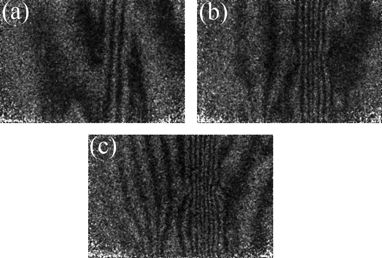
(a) to (c) Dark line patterns resulted from the shearography test of the injection-molded composite with 40 wt% wood content 1, 2, and 3 s after unloading, respectively, for the bilateral constraining.
In order to evaluate the accuracy of the obtained results, other experiment was also carried out, in such a way that the specimen was constrained only at one side. The loading condition was the same as the previous experiments in which thermal stressing by heat radiation was applied according to the pattern shown in Figure 3.
Figures 8(a) to (c) shows the shearography results for this configuration, and as it is clear, the images suggest the presence of defect in the subsurface layers of the composite. The broken dark lines present the disintegration of the composite structures in the sublayers, which lead to the deviation of reflected lights from the surface of the specimens. The length of this deviation was estimated to be up to 7 mm.
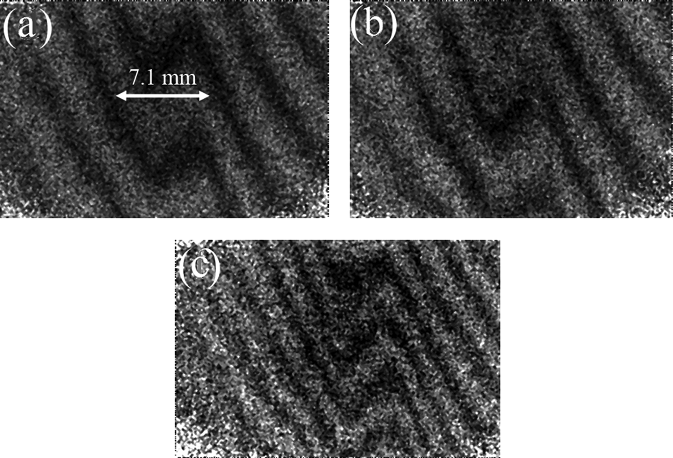
(a) to (c) Dark line patterns resulted from the shearography test of the injection-molded composite with 40 wt% wood content 1, 2, and 3 s after unloading, respectively, for the one-end constraining.
The reasons for these defects could be due to: (1) low packing condition, that is, composites with a higher volume fraction of the fillers exhibits a higher viscosity that makes the material more difficult to pack, (2) agglomeration of wood particles, as it was discussed earlier that a higher content of wood particles promotes agglomeration of wood components in the matrix which causes debonding and crack in composites structure, and (3) poor adhesion of wood content would further increase the possibility of poor interface attachment between wood and polymeric matrix.
Conclusion
In this article, the shearography was successfully used as an NDT method for WPCs inspection. WPCs with different volume fraction of wood powder were tested utilizing shearography method. The results suggest the following conclusions:
The shearography of a wood–plastic specimen with a drilled hole (as an intentional defect) shows the formation of the fringe pattern in the filtered images, which is an indication of successful application of this method for inspection of WPCs.
WPCs with different volume fraction of filler showed various pattern of vertical dark lines presenting the presence or absence of defect in them.
The specimen with lower fraction of wood powder showed no defect, while the specimen with highest fraction of the wood powder presented the evidence of defect.
Footnotes
Declaration of Conflicting Interests
The author(s) declared no potential conflicts of interest with respect to the research, authorship, and/or publication of this article.
Funding
The author(s) received no financial support for the research, authorship, and/or publication of this article.