
Abstract
A sampling chamber was developed for emission testing of diisocyanates, methylene diphenyl diisocyanate (MDI), toluene diisocyanate (TDI), and corresponding diamines, methylene diphenyl diamine (MDA), and toluene diamine (TDA) from polyurethane (PU) product surfaces. In addition, a methodology for validation of the sampling chamber was presented, based on the introduction of generated standard atmospheres of the different diisocyanates and diamines to the sampling chamber system. Sampling of diisocyanates and diamines was performed on a circular glass fiber filter (150 mm diameter) impregnated with dihexyl amine (DHA) and acetic acid (AA) positioned inside a cylindrical stainless steel sampling chamber. The diisocyanates were immediately derivatized to DHA derivatives, and the amines were derivatized in a subsequent work-up procedure with ethyl chloroformate (ECF). The design of the sampling chamber and the presented methodology allowed for simultaneous sampling and analysis of diisocyanates and diamines of emission from a large surface area with minimal interior wall interaction in the sampling chamber. Performance characteristics of the sampling chamber for different sampling times and air humidity were obtained by determining collected amounts of the diisocyanates and diamines in the different parts of the sampling chamber. The repeatability of the collected amount on the impregnated filters in the sampling chamber was 15% with an overall recovery for 8 h of sampling in the range of 61% to 96%. The performance of the sampling chamber was not affected by air humidity (5%–75% RH), and no breakthrough during sampling was observed. LC-MS/MS determinations allowed for emission testing of diisocyanates and diamines on product surfaces as low as 10–30 ng m−2 h−1.
Keywords
Introduction
The applications and use of polyurethane (PU) products are extensive, and they can be found in almost every sector of the industry (Baysal and Kasapbası, 2017). For production of PU polymers, diisocyanates and polyols are used. Diisocyanates are irritants of the upper airways, skin, and eye, as well as dermal and respiratory sensitizers (ECHA, 2021). Overexposure to diisocyanates is a common cause for developing occupational asthma (Ameille et al., 2003; Lefkowitz et al., 2015). Even though a decrease of diisocyanate work-related asthma has been observed in recent years (Buyantseva et al., 2011; Paris et al., 2012; Reilly et al., 2020), exposure considerations are still important.
The majority of PU products are made using methylene diphenyl diisocyanate (MDI) and toluene diisocyanate (TDI). During production of water-blown PU foams, formation of low levels of the corresponding diamine may occur (Karlsson et al., 2022a; Marand et al., 2004): methylene diamine (MDA) in the case of MDI and toluene diamine (TDA) in the case of TDI. Aromatic diamines are of concern as potential human carcinogens (IARC, 1978, 1986). Diamines in air have been detected not only during the thermal degradation of PU (Karlsson et al., 2002) but also during the production of water-blown PU foams (Jones et al., 2017). Hence, it has to be taken into account that diisocyanates and diamines may be present in the same atmosphere, which could be a source of interference (HSE, 2014).
Evaluating emissions of PU-related compounds, such as diisocyanates and aromatic diamines, from PU products is important for risk assessment. Emissions of diisocyanates have been tested in controlled-environment chambers during curing of different PU adhesives (Wirts et al., 2003; Wirts and Salthammer, 2002) and from other PU products such as various foams, varnishes, and sealants (Kelly et al., 1999). For general emission testing of non-reactive volatile and semi-volatile compounds, there are commonly used emission testing protocols that use apparatus such as the Field and Laboratory Emission Cell (FLEC®) (Wolkoff, 1996), micro-scale chambers (ASTM D7706-11:2017; ISO 16,000-25:2011), and more conventional small-scale chambers (ASTM D7143-11:2016).
For the collection of reactive compounds, such as diisocyanates, it is important to instantaneously derivatize the isocyanate (NCO) functional group to avoid losses. When using the above emission testing protocols, there is a significant risk of bias due to wall adsorption in the various emission chamber systems. An attempt to overcome the wall effects was performed by the introduction of a derivatization procedure using the existing FLEC system and a modified micro chamber (Sebroski et al., 2014). A derivatization procedure was introduced, the interior of the FLEC system was coated with 1-(2-pyridyl) piperazine (1,2-PP) as the derivatizing agent, and an internal sampling filter containing 1,2-PP was placed inside a micro chamber prototype, with the filter fitted directly above the sample. Using this approach, a proof of concept was demonstrated for product emission testing of MDI.
The aim of this study was to construct a sampling chamber with a similar design to the modified micro chamber, presented by Sebroski et al. (2014), with the derivatization of NCO groups, using a larger sample area, with reduced wall effects and the possibility to perform simultaneous sampling for the analysis of diisocyanates and diamines. An additional goal was to develop and carry out a validation procedure for the sampling chamber system for recovery estimations of diisocyanates and diamines.
Experiment
Chemicals
Water, NaOH, KH2PO4, dibutyl amine (DBA), dihexyl amine (DHA), acetonitrile (ACN), acetic acid (AA), formic acid (FA), methanol (MET), toluene (TOL), 4,4′-methylene dianiline (MDA), TDA, TDI (isomer mixture of 75%/25% 2,4- and 2,6-TDI), pyridine, and ethyl chloroformate (ECF) were obtained from Merck (Darmstadt, Germany).
Technical grade MDI (containing 2,4′-MDI and 4,4′-MDI at a ratio of 0.04/1) was obtained from Huntsman (Everberg, Belgium).
Deuterium-labeled di-(d9-DBA)-derivatives of the isomers of TDI and MDI, dideuterium-labeled 4,4′-MDA [CD2(C6H4NH2)2], trideuterium-labeled 2,4-TDA, trideuterium-labeled 2,6-TDA [CD3C6H3(NH2)2], 2,2′-MDA, and 2,4′-MDA were obtained from Ramidus (Lund, Sweden).
Reference solutions
Solutions containing DHA and DBA derivatives of MDI and TDI were prepared by adding one drop (approximately 50 mg) of the respective isocyanate substance (technical grade MDI and TDI isomer mixture) to 10 mL TOL solutions. 100 μl of each of the isocyanate solutions were added to 10 mL of 0.1
Instrumentation
A triple quadrupole mass spectrometer (MS), Quattro Micro (Waters, Altrincham, Cheshire, UK), and Shimadzu LC10ADVP micro-LC pumps (Shimadzu Corporation, Kyoto, Japan) with sample injections of 1 μL using an LC-Pal autosampler (CTC Analytics AG, Zwingen, Switzerland) on an Ascentis Express analytical column (5 cm × 2.2 mm, 2.7 μm C18; Supelco, Bellefonte, PA, USA) were used.
The MS instrument was monitoring multiple reactions in the positive electrospray mode. Quantitative measurements were made by monitoring the reactions [MH]+→[DBAH]+ and [MH]+→[DHAH]+ for the isocyanate derivatives and [MH]+→[M-46]+ for the diamine derivatives and for the corresponding deuterium-labeled internal standards ([MH]+→[d9DBAH]+ and [d2MH]+→[d2M-46]+). For chromatographic separation of the derivatives, gradient elution was performed from 60/40/0.05 to 95/5/0.05 ACN/H2O/FA in 6 min. After that the mobile phase was maintained at 95/5/0.05 ACN/H2O/FA for 13 min at a flow rate of 0.4 mL/min.
A more detailed description of the instrumental parameters for the analysis of isocyanate–DBA and amine-ECF derivatives using LC-MS is available elsewhere (Gylestam et al., 2014; ISO 17,734-1:2013, ISO 17,734-2:2013; Karlsson et al., 2002).
Generation system
The generation system consisted of a cylindrical stainless-steel container (diameter = 60 mm and height = 100 mm) with a stainless-steel tubing inlet and a stainless-steel tubing outlet.
For the generation of TDI vapor, TDI-gas/liquid permeation was performed inside the stainless-steel container. A 2 mL glass vial with a 2 cm silicon tubing was attached to the vial, containing TDI (isomer mixture) at a level of approximately 5 mm above the glass vial, enabling liquid permeation through the silicon tubing. The silicon tubing was plugged at the upper end with a polypropylene plug. The generation system containing the TDI–glass vial–silicon tubing permeation apparatus was placed in a temperature-controlled water bath at 30°C, with water up to approximately 5 cm of the stainless-steel container.
For the generation of MDI, MDA, and TDA vapor, approximately 1 g of MDI (technical grade), 1 g of MDA, and 1 g of TDA were placed in an open 5 mL glass vial which was then placed in the generation system. The generation system containing the vial with MDI, MDA, or TDA was placed in a water bath at 50°C for MDI and 70°C for TDA and MDA, with water up to approximately 5 cm of the side of the stainless-steel container.
A generation flow inlet of 40 mL/min nitrogen was used. A dilution flow of 160 mL/min was introduced immediately at the outlet of the generation system stainless-steel container.
Sampling chamber for emission testing
Description
A sampling chamber was designed for emission testing of diisocyanates and corresponding diamines (Figure 1) from a product sample surface. Sampling of diisocyanates and diamines was performed on a circular glass fiber filter (150 mm diameter) impregnated with DHA and AA. The chamber design featured a minimized wall surface area available for adsorption (wall surface area to filter surface area ratio of 0.5) A crosscut view of the sampling chamber designed for product emission testing (1) and for sampler validation (2). The two sampling chambers containing the stainless-steel cylindrical wall unit (A) and a stainless-steel cylindrical base unit (B) that holds the dihexylamine-impregnated filter (C) together with a polytetrafluoroethylene (PTFE) retaining plate (D). The retaining plate was fitted between a PTFE distance ring (E) and a stainless-steel lid (F). Two air inlets were in the base unit and the air outlet in the stainless-steel lid. The sampling chamber is designed to be mounted on the top of the FLEC® FL-2001 sample holder (CHEMATEC, Roskilde, DK).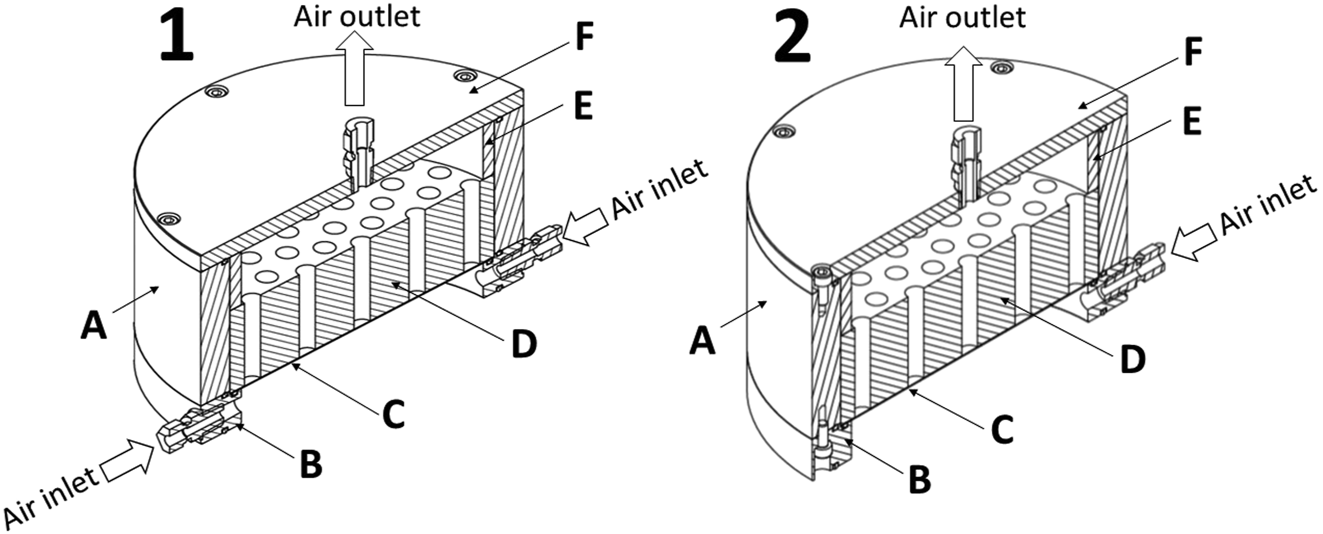
The sampling chamber was made of a stainless-steel cylindrical wall unit and a stainless-steel cylindrical base unit that holds the filter together with a PTFE retaining plate. The retaining plate was fitted between a PTFE distance ring and a stainless-steel lid. Two air inlets were in the base unit and the air outlet was in the lid. The air flow was directed and distributed through the filter by the holes in the PTFE retaining plate. O-rings were placed between the base unit and wall unit and between the wall unit and lid. An O-ring was also placed between the base unit and the glass fiber filter. The design of the sampling chamber allowed mounting it on the top of an FLEC® FL-2001 sample holder (CHEMATEC, Roskilde, DK) for product emission testing.
In addition, an almost identical sampling chamber was designed for performing sampling chamber validation (Figure 1). The only difference between the two sampling chambers was the air inlet. The sampling chamber used for validation testing contained only one inlet in the base unit for direct connection to a standard atmosphere outlet. The sampling chamber designed for material emission testing had two inlets in the base unit.
Derivatization
Testing of the diffusion of the derivatization reagent from the sampling filter to the sample surface during sampling was conducted for different derivatization reagents: dibutyalmine, dihexylamine, and dioctylamine. Glass fiber filters (∼300 cm2) were coated with the different diamines as AA ion pairs. Additional filters (∼300 cm2) were impregnated with technical grade MDI (approximately 1 μg/cm2). The reagent coated filters were placed in the filter holder in the sampling chamber. A filter impregnated with MDI was placed on a stainless-steel plate representing the sample surface. The degree of diffusion from the reagent-coated filters was studied by determining the level of MDI-amine derivatives on the MDI-impregnated filters. The diffusion testing was performed at ambient temperature during 3 h at a flow rate through the sampling chamber system of 200 ml/min.
The MDI-impregnated filters were cut into four pieces. Each piece of the filter media was worked up according to the work-up procedure. The MDI-amine derivatives were quantified to determine the amount of diffused reagent on the sample surface.
Characterization
The sampling chamber system was characterized with regards to sampling repeatability, recovery, and breakthrough.
Repeatability data were obtained by performing repeated sampling (n = 5) on a TDI standard atmosphere for 30 min. Before each sampling procedure, the sampling chamber system was thoroughly cleaned according to the described wash procedure. The total duration of the repeatability test was approximately 10 h.
For recovery testing, sampling of TDA, MDA, TDI, and MDI was performed for 2 h and 8 h, respectively. The air flow through the sampling chamber was 200 ml/min, and measurements were collected at humidity levels between 5% and 75%.
The sampling chamber containing the DHA-impregnated filter was placed on the top of a stainless-steel plate with the inlet connected to the generation flow (Figure 2). The diisocyanate and diamine concentration in the generation flow was measured before and after each sampling chamber test. Diisocyanate air samples from the generation flow outlet were collected using an isocyanate sampler (ASSET-NCO, Supelco, Bellefonte, PA, US) sampling at a flow rate of 500 ml/min for 10–20 min. Diamine air samples from the generation flow outlet were collected using an impinger-filter sampler (Karlsson et al., 2002), containing 10 ml of 0.01 Setup for toluene diisocyanate (TDI) recovery testing. The generation system consisting of a stainless-steel container (A) with a nitrogen generation flow inlet (B). Inside the stainless-steel container, there is a glass vial (F) with a silicon tubing (D) attached containing TDI (E). The silicon tubing was plugged with a polypropylene cap. To the outlet of the generation flow, a dilution flow of air (H) was connected. The diluted generation flow was connected to the air inlet of the sampling chamber system (J). The sampling chamber system base unit was placed on the top of a stainless-steel plate (I). At the outlet of the sampling chamber system, an ASSET sampler (K) was connected for sampling of possible breakthrough.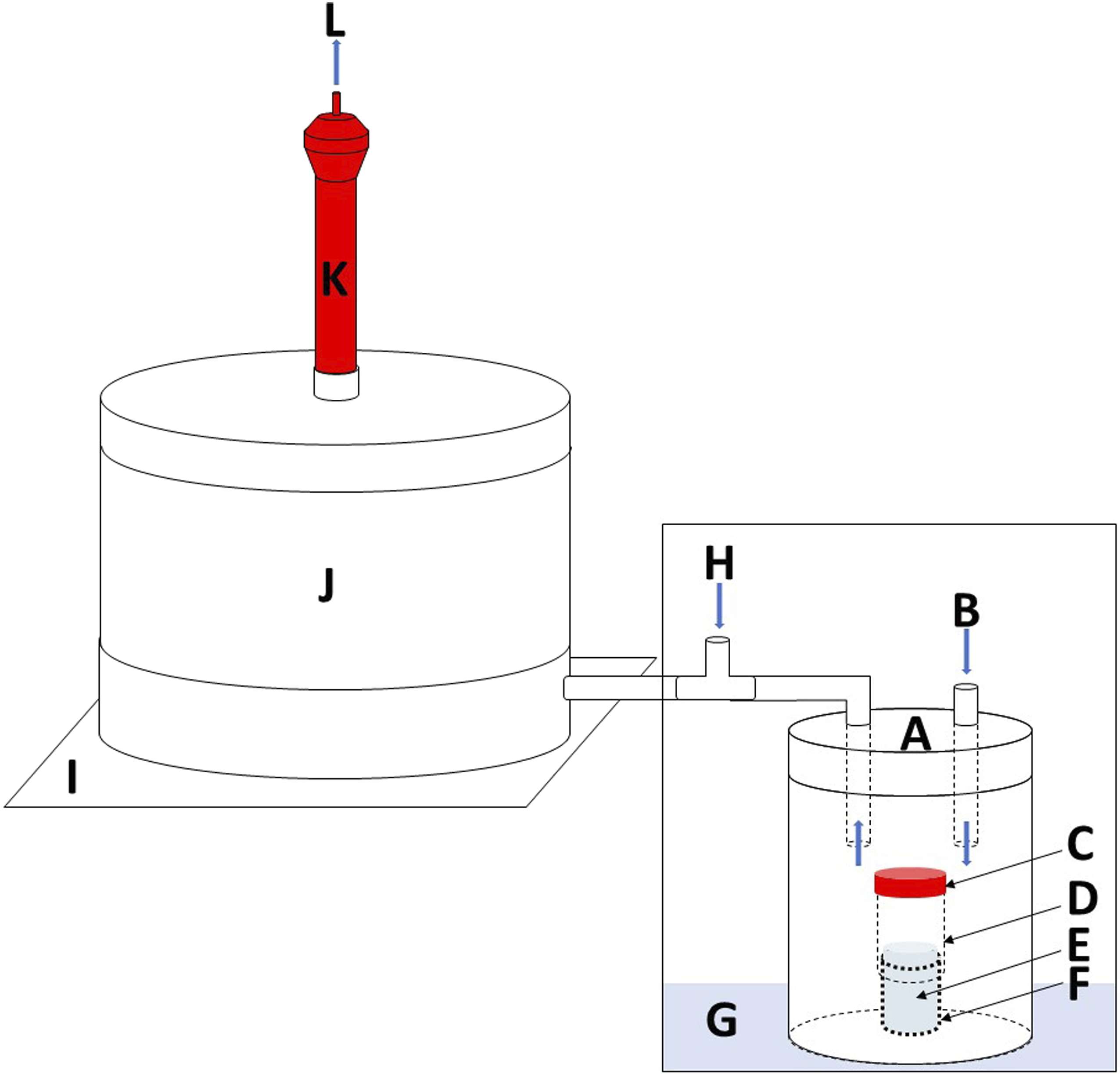
For breakthrough measurements, an isocyanate sampler (ASSET) or amine sampler (impinger-filter) sampled the outlet of the sampling chamber at a flow rate of 500 ml/min during the test.
For each recovery test, four different kinds of samples were collected from the sampling chamber system and analyzed for TDA, MDA, TDI, or MDI, depending on the substance that was tested. 1. DHA filter samples: After sampling, the DHA-impregnated filter was cut into four equal pieces. Each filter piece was placed in 5 ml TOL and was worked up as one sample. 2. Sampler inlet sample: After sampling, the generation atmosphere inlet of the sampling chamber (i.e., base inlet connection) was rinsed with 5 ml 0.01 3. Plate surface samples: After sampling, the stainless-steel bottom plate surface was wiped with a 5 × 5 cm TOL-moistened glass fiber filter. After the wipe sampling, the filter was placed in 5 ml 0.01 4. Wall surface samples: After sampling, the inner wall surface of the sampling chamber was wiped with a 5 × 5 cm TOL-moistened glass fiber filter. After the wipe sampling, the filter was placed in 5 ml 0.01
All samples for both diamine and diisocyanate determinations were worked up in accordance with the work-up procedure described in the next paragraph.
Work-up procedure—DHA filter samples/DHA test tube samples
For diisocyanate determinations, volumes of 3 ml of 1 mmol/l H2SO4, 3 ml of MET, and 100 μl of internal standard (ACN solution containing deuterium-labeled isocyanate derivatives at 1 μg/ml) were added to the test tubes containing the sample. The test tubes were then shaken for 5 min, sonicated for 10 min in an ultrasonic bath, and again shaken for 20 min to extract the isocyanate DHA derivatives to the organic phase. After centrifugation for 10 min at 1800 × g (Jouan C312, Jouan Industries, Saint-Herblain, France), the TOL solution was separated and transferred to new test tubes. To the tubes containing the remaining mixture of MET and acid (and, for some sample types, a filter also), another aliquot of 5 mL of TOL was added, and the extraction procedure was repeated. The TOL was separated and transferred to the test tubes containing TOL from the first extraction. The TOL solutions were then evaporated to dryness using a vacuum centrifuge (model SC210 A; Savant Instruments Inc., Holbrook, NY, USA). To the dry residues, 0.1 ml ACN was added, and the DHA derivatives were dissolved during sonication. The ACN solution was transferred to a vial for LC-MS/MS analysis.
For diamine determinations, volumes of 3 ml of 5 mol/l NaOH and 50 μl diamine internal standard (acidic solution containing deuterium-labeled diamines at 10 μg/ml) were added to the test tubes containing the samples. The test tubes were then shaken for 5 min, sonicated for 10 min in an ultrasonic bath, and again shaken for 20 min to extract the amines to the organic phase. After centrifugation for 10 min at 1800 × g, the TOL solution was separated and transferred to new test tubes. To the tubes containing the remaining mixture of NaOH (and, for some sample types, a filter also), another aliquot of 5 ml of TOL was added, and the extraction procedure was repeated. The TOL was separated and transferred to the test tubes containing TOL from the first extraction. Volumes of 3 ml of 5 mol/l NaOH, 10 μl of pyridine, and 50 μl ethyl chloroformate were added to the TOL solution. The test tubes were then shaken for 10 min. After centrifugation for 10 min at 1800 × g, the TOL solution was separated and transferred to new test tubes. The TOL solutions were then evaporated to dryness using a vacuum centrifuge. To the dry residues, 0.1 ml ACN was added, and the DHA derivatives were dissolved during sonication. The ACN solution was transferred to a vial for LC-MS/MS analysis.
Work-up procedure—impinger-filter samples
Impinger-filter sampling was only performed for diamine determinations in the generation flow and from the outlet of the sampling chamber for breakthrough determinations. After sampling, internal standard was added to the impinger solutions (50 μl acidic solution containing 10 μg/ml deuterium-labeled diamines), the diamines were extracted, and worked up according to Karlsson et al., (2002) (ISO 17,734-2:2013), followed by LC-MS/MS analysis.
Work-up procedure—ASSET samplers
Isocyanate sampling using the ASSET samplers was only performed for isocyanate determinations in the generation flow and from the outlet of the sampling chamber for breakthrough determinations. After sampling, the isocyanate derivatives formed were extracted from the filters and worked up according to Gylestam et al. (2014) (also, ISO 17,734-1:2013).
During the work-up, internal standard was added to the extraction (100 μl ACN solution containing 1 μg/ml deuterium-labeled isocyanates). After the work-up, LC-MSMS analysis was performed.
Sampling chamber wash procedure
Before initiating a new sampling procedure with the sampling chamber system, the PTFE retaining plate was placed in ethanol for 30 min, whereupon all holes were mechanically rinsed with a small brush and ethanol and allowed to dry. The base unit and the inlet connection on the base were placed in separate containers containing ethanol and sonicated for 20 min. The inlet of the base unit was mechanically rinsed with a small brush and ethanol. The O-ring between the impregnated filter and base unit was exchanged between each use. All O-rings were carefully wiped with ethanol-soaked paper cloth. All parts were allowed to dry before reassembling the sampling chamber.
Results
Derivatization reagent
During sampling for 3 h using different amine-AA impregnated filters, differential diffusion of the amine reagent was noted in direct relation to the volatility of the amine: using DBA-AA impregnated filter resulted in 0.2% of the total DBA load on the substrate surface, using DHA-AA impregnated filter resulted in 200 ppm of the total DHA load on the substrate surface, while using DOA-AA impregnated filter resulted in 1 ppm of the total DOA load on the substrate surface.
Work-up and analysis
The chromatographic properties of the isocyanate-DBA and amine ECF derivatives have previously been described (Karlsson et al. 2002, 2005). Compared to the DBA derivatives, the DHA derivatives were considerably more retained on the reversed phase column (Figure 3). Despite the big difference in retention times, it was possible to obtain good calibration plots for the DHA derivatives using the deuterium-labeled DBA derivatives as internal standards. The calibration range of the calibration standards was 0.05–0.9 μg for TDA and MDA, 0.05–1.3 μg for 2,4-TDI, 0.01–0.2 μg for 2,6-TDI, and 0.005–0.7 μg for MDI (7–10 calibration standards distributed within the calibration range). For the analytes having a corresponding deuterium-labeled internal standard (MDA-ECF, TDA-ECF, MDI-DBA, and TDI-DBA), correlation coefficients were typically >0.998. For the MDI-DHA and TDI-DHA, the correlation coefficients were typically >0.992. Liquid chromatography tandem mass spectrometry (LC-MSMS) chromatograms of a calibration standard containing 0.5 μg of A: methylene diphenyl diisocyanate (MDI)-dihexylamine (DHA) (m/z = 622→186), B: toluene diisocyanate (TDI)-DHA (m/z = 546→186) and 0.1 μg of the internal standards, C: MDI-d18 dibutylamine (DBA) (m/z = 527→139), and D: TDI-d18-DBA (m/z = 451→139).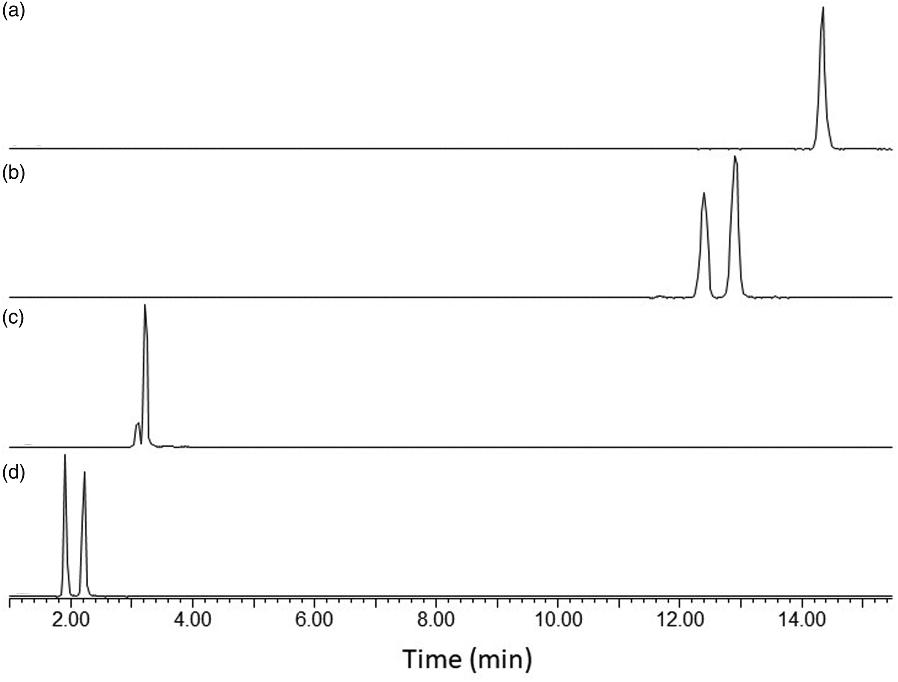
The calibration range was selected for practical reasons with regards to analyte amount in the samples. The limit of quantification (LOQ) was defined as the lowest calibration point for all analytes. By lowering the calibration range, the LOQs could be lowered further to 0.3 ng for the diisocyanates and 2,4-TDA, and to 1 ng for 2,6-TDA and MDA (Karlsson et al., 2022a, 2022b).
The size of the filter media in the samples was found to make efficient extractions more difficult than normal ASSET sampler extractions. For efficient extraction it was necessary to divide the filter into four pieces, thereby generating four samples for each individual sampling chamber filter. It was also important to ensure that the filters were distributed in the test tube and not packed in the bottom of the tube and to visually determine that the extraction solution reached all parts of the filter during the shaking procedure. For spiked solutions, the recoveries were in the range of 94%–105% for all compounds. The variation for 10 spiked filter samples was below 10% relative standard deviation (RSD).
Generation of standard atmospheres
It was possible to maintain stable air concentrations during an 8 h test with a variation of less than 10%. However, the system was slow to reach equilibrium and, especially for MDI and MDA, it could take several days before a steady state was obtained and stable concentrations were achieved. Once the system was stabilized, it was possible to maintain the generation for weeks, with a small decrease or increase depending on permeation generation (TDI) or generation from an open container (TDA, MDA, and MDI). Performing repeated generations with the same compound was easier than switching between amine or isocyanate generation. Thorough cleaning of the system and allowing extensive time for stabilization were necessary when switching between compounds.
For the different recovery tests, the generated concentrations of MDI and MDA were in the range of 1–6 μg/m3 and for TDI and TDA in the range of 100–500 μg/m3. For the repeatability testing, TDI concentration of approximately 1 mg/m3 was generated.
Sampling chamber characterization
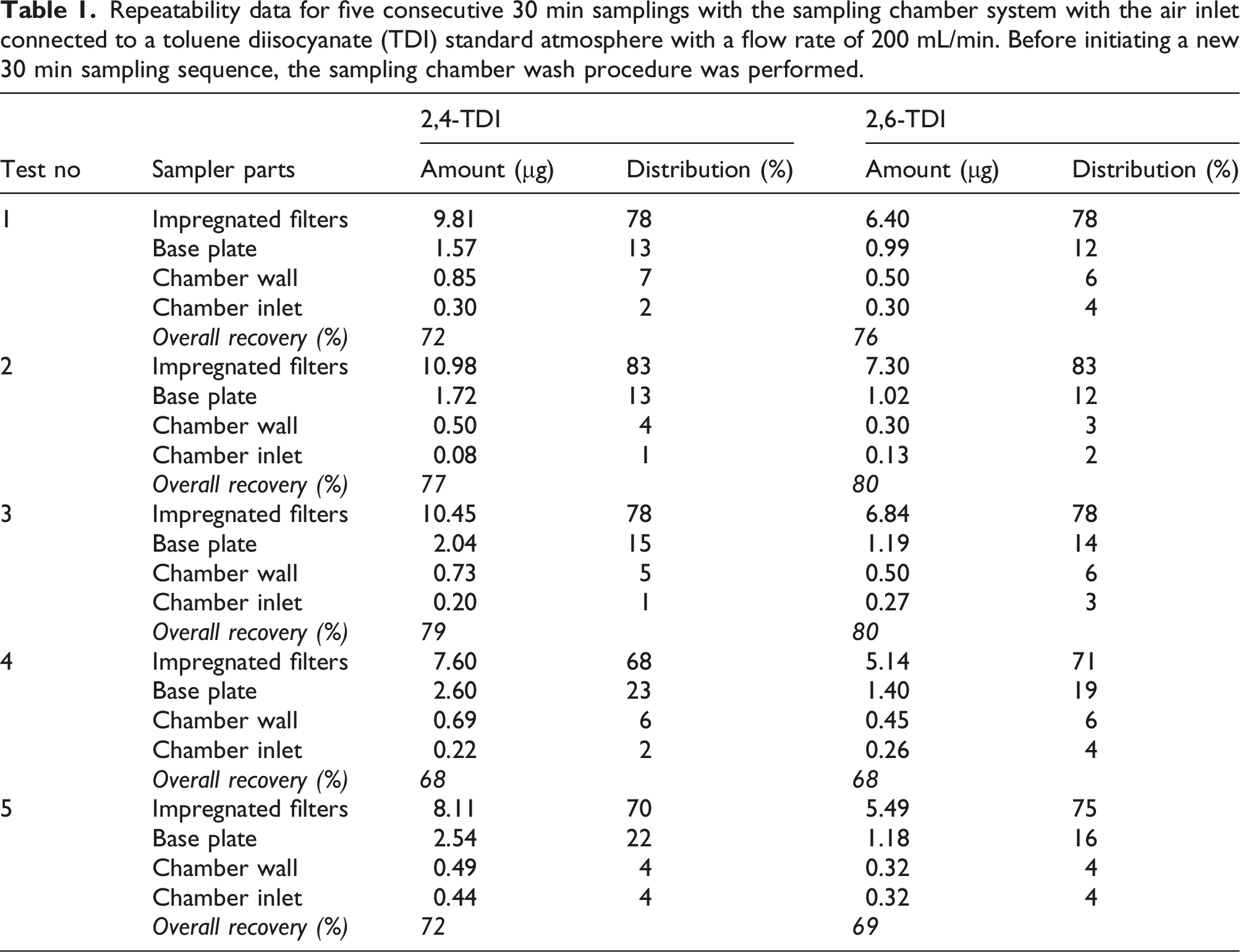
Variation
Repeatability data for five consecutive 30 min samplings with the sampling chamber system with the air inlet connected to a toluene diisocyanate (TDI) standard atmosphere with a flow rate of 200 mL/min. Before initiating a new 30 min sampling sequence, the sampling chamber wash procedure was performed.
Sampling chamber characterization—humidity impact
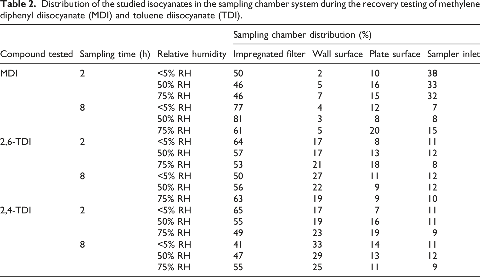
Distribution of the studied isocyanates in the sampling chamber system during the recovery testing of methylene diphenyl diisocyanate (MDI) and toluene diisocyanate (TDI).
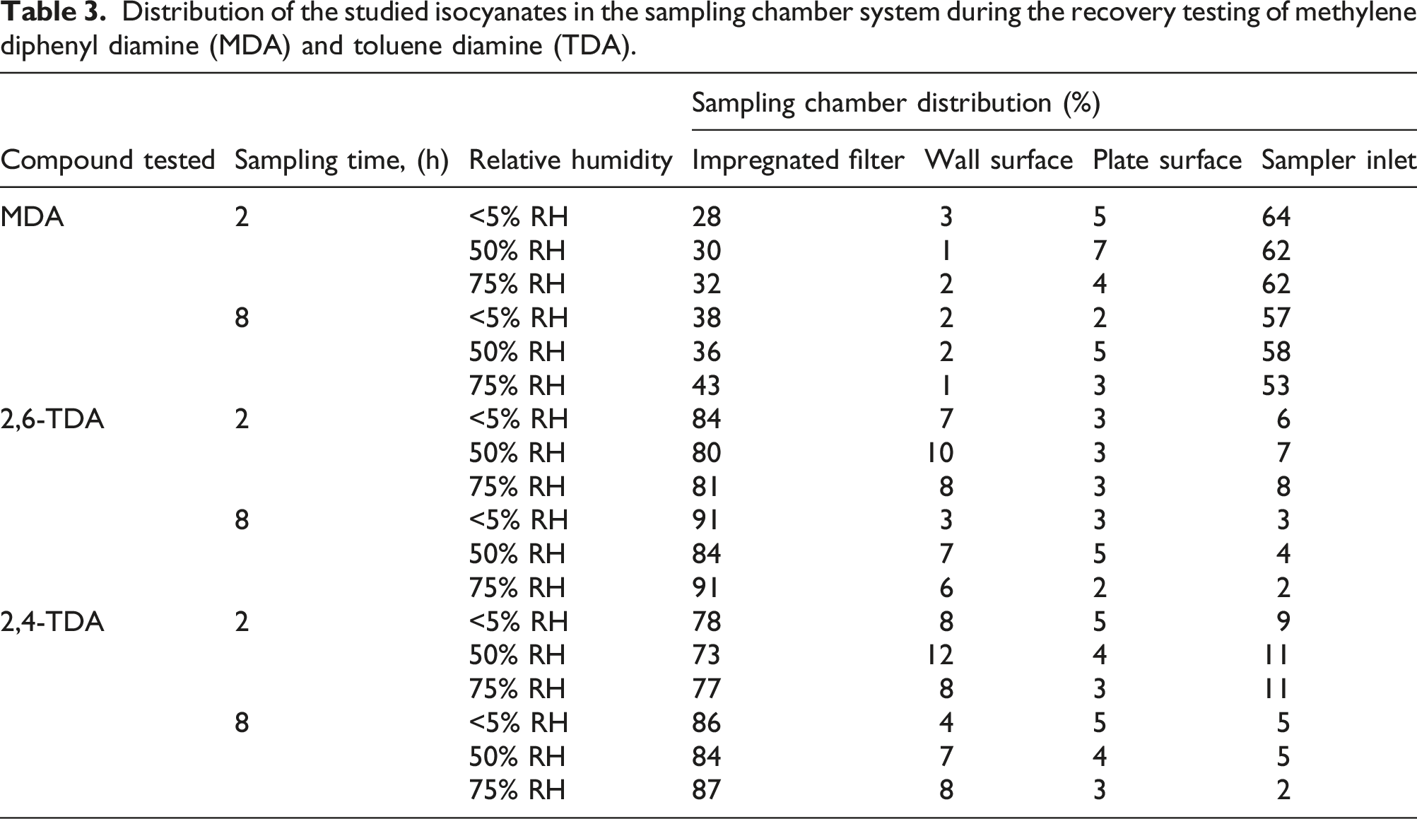
Distribution of the studied isocyanates in the sampling chamber system during the recovery testing of methylene diphenyl diamine (MDA) and toluene diamine (TDA).
Sampling chamber characterization—recovery MDI, TDI and MDA, and TDA
For 2 h sampling, the total MDI recovery for the sampling chamber system compared to the air concentrations determined in the generation flow was in the range of 78%–82%. For 8 h of sampling the total MDI recovery was in the range of 68% to 89%. For the two and 8 h of sampling, more than 45% of the MDI content was found on the impregnated filter. Less than 4% of the MDI content was found on the wall surface, less than 33% was fond in the sampler inlet and less than 24% was found on the bottom plate surface.
For 2 h sampling, the total TDI recovery for the sampling chamber system compared to the air concentrations determined in the generation flow was in the range of 71% to 76%. For 8 h of sampling the total TDI recovery was in the range of 61–68%. For the two and 8 h of sampling, more than 45% of the TDI content was found on the impregnated filter. Less than 30% of the TDI content was found on the wall surface, less than 12% was fond in the sampler inlet and less than 20% was found on the bottom plate surface.
For 2 h sampling, the total MDA recovery for the sampling chamber system compared to the air concentrations determined in the generation flow was in the range of 90% to 97%. For 8 h of sampling, the total MDA recovery was in the range of 80% to 96%. For the 2 and 8 h of sampling, more than 28% of the MDA content was found on the impregnated filter. Less than 3% of the MDA content was found on the wall surface, approximately 64% was found in the sampler inlet, and less than 7% was found on the bottom plate surface.
For 2 h sampling, the total TDA recovery for the sampling chamber system compared to the air concentrations determined in the generation flow was in the range of 68% to 90%. For 8 h of sampling, the total TDA recovery was in the range of 70%–96%. For the 2 and 8 h of sampling, more than 70% of the TDA content was found on the impregnated filter. Less than 12% of the TDA content was found on the wall surface, less than 10% was found in the sampler inlet, and less than 5% was found on the bottom plate surface.
Discussion
Existing techniques for product surface emission testing are not designed for testing of semi-volatile, reactive compounds such as isocyanates. To minimize wall effects, it is crucial that the isocyanates are immediately derivatized in order to maintain acceptable recovery during testing and that the design of the testing chamber should minimize the wall surface area available for adsorption. The reactive nature of isocyanates makes the validation of the testing procedure troublesome since stable test atmospheres need to be generated and maintained during a prolonged period of time.
For the presented sampling chamber system, DHA was used instead of DBA in combination with AA (ISO:17734-1:2013) to reduce volatility and loss of the derivatizing agent during the test. Using dioctylamine as a derivatization reagent would reduce the volatility even more. However, advantageous chromatographic properties of the isocyanate-DHA derivatives made DHA the preferred choice.
The estimated overall recoveries determined in this study were based on comparison of the introduced generated test atmosphere concentrations with the total amount determined in the sampling chamber system. This included the amount collected on the impregnated filters, the deposited quantity removed from the inner walls of the sampling chamber and on the stainless-steel base plate, and the amount found in the inlet rinse samples. Significant amounts were found in the inlet rinse samples and in the wipe samples from the base plate. The recovery of the rinsing and wiping procedure was not studied, and there will probably also be substance losses on the internal chamber surfaces during the sampling time. During actual emission testing of products, the losses in the recovery testing related to the generation flow inlet and base plate would not be relevant since the base plate would be replaced with the surface of the product being tested and any emissions of diamine or diisocyanate would occur within the sampling chamber from the product surface. Therefore, for emission testing of products, the actual diamine and diisocyanate recoveries can be assumed to be greater than the total recoveries determined for the entire test setup. For 8 h emission testing of PU products using the presented sampling chamber system, recoveries of more than 60% for diisocyanates and more than 70% for diamines are expected.
Controlling the generated concentrations and performing repeated sets of generation cycles (cleaning procedure and new loading of isocyanate/amine material) and producing similar generated concentrations were difficult, especially for TDI. The most stable generations of TDI were obtained with liquid permeation of the silicon tubing, resulting in relatively high concentrations (>100 μg/m3). For MDI and MDA, difficulties with condensation in the generation system container and connecting tubing resulted in a very slow process and much lower concentrations.
To minimize connections and tubing between the generation system and the sampling chamber and to allow the best possibilities for determination of the concentration in the introduced generation flow, a setup using a single inlet to the sampling chamber was designed. However, for product testing, a design with dual inlets was presented as it introduces a more uniform air flow above the sample surface, also a more uniform collection on the impregnated glass fiber filter.
For the characterization of the sampling chamber system, each test resulted in nine individual samples to be analyzed in addition to blank samples for testing of contamination and carry-over from previous testing. For product emission testing, the impregnated filter samples and the wipe sampling of the sampling chamber inner wall should be put through the work-up. The diisocyanates and diamines could be simultaneously determined in the same DHA-filter and wipe samples using the presented work-up procedure for diamines with ethyl chloroformate derivatization.
The LOQ presented in this study is a result of the chosen calibration range. For product emission testing, where very low concentrations of diisocyanates or diamines would be expected, the LOQs can be lowered significantly by lowering the calibration range, increased enrichment of the samples during work-up, and by thorough optimization performance of the MS-instrument prior each analysis sequence. By optimizing the LOQs, emissions as low as 0.01–0.03 μg m−2 h−1 can be monitored.
Conclusion
Simultaneous sampling and determination of surface emissions of diamines and diisocyanates were enabled using the presented sampling chamber with minimal wall surfaces.
Efficient derivatization of the isocyanates on the DHA-impregnated filter was performed. No sampler breakthrough was observed, and maintained performance of the sampling chamber system was demonstrated for the diamines and diisocyanates during increased sampling time and increased air humidity.
For PU product surface emission testing, the sampling chamber system with a dual air inlet should be used. Emitted diamines and diisocyanates should be determined on the DHA-impregnated filter samples and on the wipe samples of the sampling chamber inner wall. The estimated total recoveries for 8 h sampling (in the range of 61%–96%) and LOQs at the ng m−2 h−1 level demonstrated the potential of the developed sampling chamber for PU product surface emission testing.
Footnotes
Acknowledgments
The author wish to express appreciation to Patrick Plehiers and Mark Spence (International Isocyanate Institute, Inc.) for reviewing the manuscript.
Declaration of conflicting interests
The author(s) declared no potential conflicts of interest with respect to the research, authorship, and/or publication of this article.
Funding
The author(s) disclosed receipt of the following financial support for the research, authorship, and/or publication of this article: The research reported in this work was sponsored by the International Isocyanate Institute. The views expressed are those of the author(s) and not necessarily of the sponsor or its members.
Ethical approval
The work did not involve interaction with human study subjects, and ethical approval was not required.