
Abstract
This review firstly investigates thermoplastic materials and their composites with a particular focus on manufacturing processes of stamp forming, automated fiber placement (AFP) and bonding techniques. These processes are widely used in advanced manufacturing for different industries such as aerospace and automotive. The main focus of this article is tools used in stamp forming, AFP, and resistance welding. Their uses and design stages are defined. Of interest, thermal analysis is important in the tooling design phase since processes for thermoplastic composite production involve high temperatures that significantly impact tool performance, cycle times, and product quality. In this literature review, a summary of several research studies, which investigated thermal analysis of tools used in different processes, is presented. Significantly, processes are mainly not optimized for thermoplastic manufacturing. The literature review reveals a major gap in existing research especially in the thermal analysis of tooling for AFP and stamp forming. This lack of thermal studies might give a critical opportunity for further investigation.
Introduction
Polymeric matrix composites are crucial in industries like aerospace, automotive, and sports due to their high strength-to-weight ratio and durability offering better performance than many metals.1,2 These materials are composed of a polymer matrix reinforced with fibers such as carbon, glass, or aramid enhancing their mechanical properties.3,4 Thermoplastic composites in particular are gaining attention for their recyclability and ease of processing making them a sustainable option compared to thermosets.5,6 Their ability to be reshaped and reused makes them essential for several applications which mainly needs sustainability and efficiency.1,3,4
Polymeric matrix composites can be classified based on their matrix material. They can be divided into thermoset and thermoplastic materials. 7 Thermosets are polymers that irreversibly harden and turn into a rigid form when cured. This curing process makes them highly resistant to heat and chemical exposure. They cannot be reshaped after curing providing unique dimensional stability and structural integrity in demanding applications. During the curing process chemical reactions irreversibly occur which leads to crosslinked chains formation. These chains prevent the material from being melted under higher temperatures and give enhanced mechanical strength. 8 Thermoplastics are another type of polymer that can be heated to soften or melt allowing them to be processed in a malleable state such as in thermoforming or molten state. Also, thermoplastic composites draw attention for their ability to be easily reshaped with heating making them more convenient for complex designs and manufacturing methods. Some common manufacturing methods for thermoplastic composites are stamp forming, AFP, compression, and injection molding. 9 Stamp forming, in particular, is applicable in production for thin and flat thermoplastic structures. It is also valued for its fast cycle times and cost-effectiveness 10 while AFP is preferred in aerospace for its precision in producing complex geometries. 11
The role of tools that can be used as tool for lay-up and autoclave processes or for the stamp forming process is important because they directly influence quality and performance of final composite parts. 3 Factors such as thermal conductivity, surface finish, and geometrical accuracy of tools affect efficiency of the process and properties of produced components. Optimizing tool design is therefore essential for enhancing production efficiency and ensuring high-quality outcomes. 12
In this review article, the focus lies on various manufacturing processes for thermoplastic composite materials, characteristics of tools used in these processes, geometrical criteria that are considered during tool design and a literature review of thermal analysis which can be conducted during the design of tools.
Thermoplastic matrix materials properties
Thermoplastics are a category of polymers characterized by their ability to soften or melt when heated making them highly versatile for various processing methods like thermoforming, 13 extrusion, 14 pultrusion, 15 and injection molding.9,16,17 These materials can be classified based on their crystalline structure 18 and main usage characteristics. 19
In terms of crystalline structure, thermoplastics are classified as amorphous or semi-crystalline. Amorphous types like polycarbonate (PC) have irregular structures and are usually transparent, while semi-crystalline types like polyethylene (PE) have both ordered and disordered regions, making them opaque (PP).
18
Thermoplastics are grouped by usage into three main types. Commodity plastics, such as PVC, PE, are low-cost and used in daily applications. Engineering plastics, such as PA, PC, offer better strength and heat resistance. High-performance types, such as polyether ether ketone (PEEK), PEI, are suited for extreme conditions with superior thermal and chemical resistance.
19
In Figure 1, classification based on crystalline structure is presented.
20
Classification of thermoplastic polymer materials based on crystalline structure.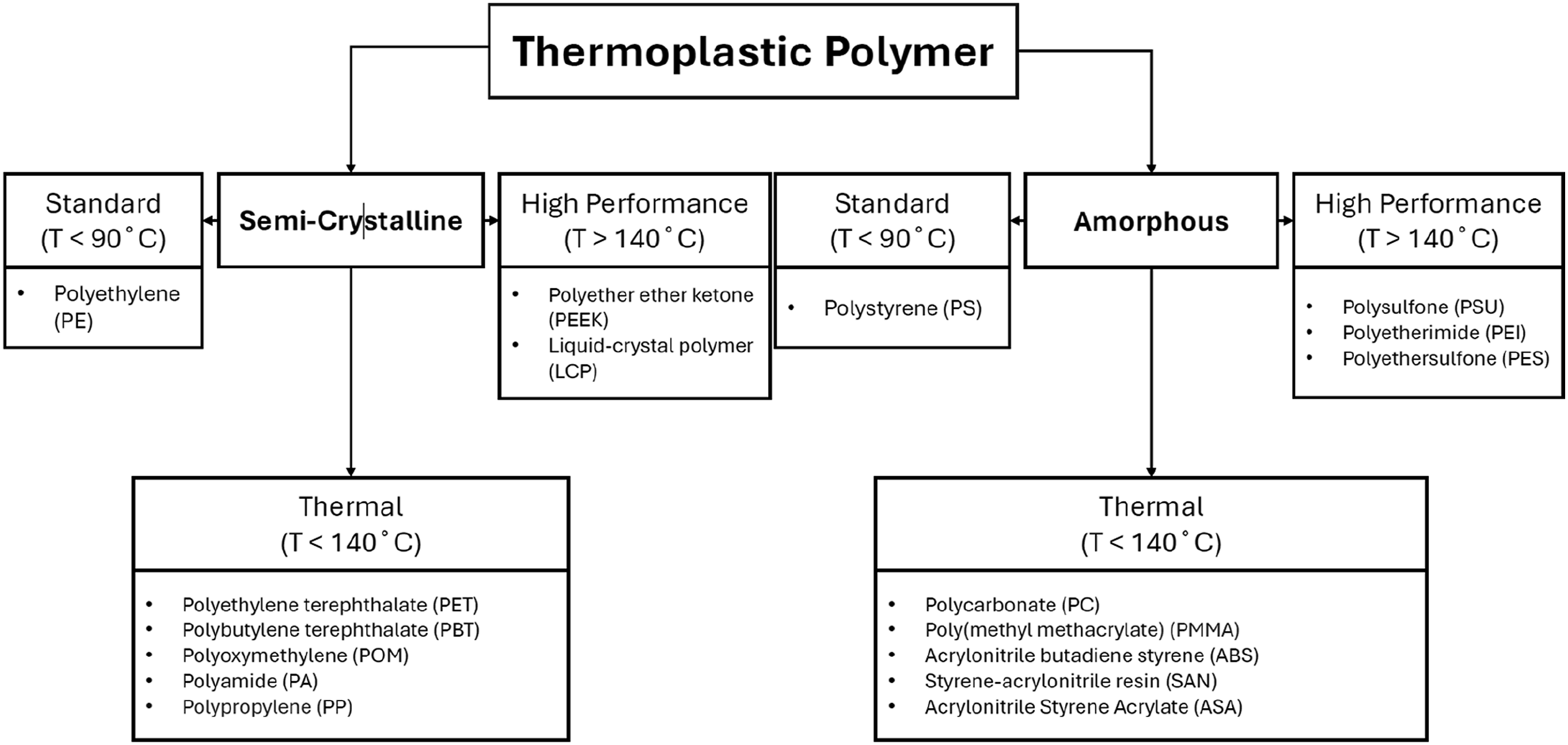
Thermoplastics also offer a significant advantage because of their recyclability. They can be reheated and reshaped several times without major changes in properties.21–23 This also reduces the demand for resources and minimizes environmental impact.24,25 Thermoplastic composites are recycled using mechanical, thermal (pyrolysis) and chemical (solvolysis) methods.23,26
Other than the advantage of recycling, thermoplastic materials have also mostly higher ductility and impact resistance than thermosets.26–28 In the aerospace industry steel and aluminum materials are widely used. Thermoplastics show lower density, melting temperature, and thermal conductivity making them lightweight and easier to process but less convenient in high-temperature conditions. 9 In addition, thanks to the additional reinforcement materials thermoplastic matrix composites can have higher mechanical properties.18,29
Thermoplastic composite materials properties
For many years due to their unique properties, thermoplastic composite materials have become a significant class and interest in advanced materials for various industries.30–33 These composites which mostly consist of continuous fibers such as carbon or glass in a thermoplastic matrix offer some advantages over traditional thermoset composites.31,34
Main properties of thermoplastic composites provide expanding use in specific applications. One of the main characteristics is their high strength-to-weight ratio. 35 Fiber reinforcements provide significant mechanical strength while the thermoplastic matrix ensures lightness. 36 In addition to strength, thermoplastic composites are known for their superior impact resistance, a property that is critical in aerospace where in-service damage must not compromise structural integrity. 31 Furthermore, they might offer excellent thermal stability and chemical resistance particularly in high-performance matrices like PEEK and polyphenylene sulphide (PPS) which can withstand high temperatures and chemical exposure without degradation. 35
In addition, ability of in situ consolidation of thermoplastic composites eliminates secondary curing. Thus, it reduces production time and costs.37,38 In situ consolidation ensures high quality bonding with accurate temperature and pressure control.38,39 It is suitable for large scale and complex geometries in combination automated methods like AFP and stamp forming. 40 Also, thermoplastics provide the advantage of no fixed shelf life. This yields possible flexible storage, reduced material wastage and cost savings compared to thermosets.41,42
In general, fiber reinforced thermoplastics can be classified based on reinforcement materials divided into carbon or glass continuous fiber, which provide high stiffness and strength to the materials. The thermoplastic matrix gives toughness, recyclability, and environmental resistance. 44
Unidirectional (UD) fiber-reinforced thermoplastics and woven fabrics are two main types of carbon fiber reinforced thermoplastics (CFRTPs). UD composite laminates ensure higher mechanical properties but challenges can be seen during forming due to their lower flexibility to obtain complex geometries. On the other hand, woven fabrics offer better formability but are less robust than their unidirectional counterparts. 43 The material selection is therefore a critical aspect in determining suitability of CFRTPs for specific applications.
Other than conventional thermoplastics nanomaterial integrated thermoplastics can offer enhanced properties due to additives like graphene.44–48 By using nano additives such as carbon nanotubes or graphene, materials achieve superior strength, thermal stability, and electrical conductivity. This makes them highly suitable for demanding applications such as aerospace applications. 45
Despite these advantages, thermoplastic composites also face challenges. 39 Higher temperatures required for melting and molding often lead to increased energy consumption and higher manufacturing costs. 49 Moreover, achieving strong fiber-matrix bonds can be difficult with thermoplastics in comparison to thermosets which may impact mechanical performance of composite parts. 5 Additionally, cost of high-performance thermoplastics like PEEK can be a limiting factor for broader application as they are generally more expensive than thermosetting resins. 19 Nevertheless, their recyclability, faster production potential, and ability to easily repair or reshape parts with heating make thermoplastic composites attractive in many industries. 50
In recent years, theoretical and experimental progress was made in the development of carbon fiber-reinforced thermoplastic composites (CFRTPs). Initially driven by need for recyclable and high-performance materials, research shifted towards understanding fundamental relationships between material composition, interfacial bonding mechanisms, and long-term durability. Surface modification strategies such as oxidation, plasma treatment, and silane coatings have been explored to improve fiber-matrix adhesion.17,39,51
Simultaneously, studies focused on optimizing manufacturing processes to arrange with unique flow and consolidation behaviors of thermoplastic matrices. Processes such as in situ polymerization, 37 vacuum infusion, 52 and in situ consolidation with automated fiber placement 38 offer reduced cycle time and improve recyclability. These methods are supported by evolving process models that consider crystallinity, thermal degradation, and interfacial healing.37,38
Development of stamp forming, laser-assisted AFP, and welding technologies have advanced our understanding of heat transfer, pressure distribution, and interlayer bonding under dynamic conditions. These insights reflect a shift from purely material driven approaches to integrated process-structure-performance optimization models. 32 Moreover, low-velocity impact and fatigue studies have confirmed improved ductility and damage tolerance of fully thermoplastic systems. 27 Overall, recent literature emphasizes that the field is no longer limited to process-specific parameters or material selection. Instead, it includes analytical and numerical modeling of thermal, mechanical, and interfacial phenomena.
Stamp forming, AFP and autoclave processes are prominent in aerospace applications. 36 Stamp forming involves heating thermoplastic sheets which are pre-consolidated and stamping them into a tool. This process allows for rapid production of complex high-precision parts with consistent quality.36,53 On the other hand, AFP is a specialized technique used for manufacturing large high-performance components. In AFP, pre-impregnated thermoplastic fibers are precisely laid in layers with heat applied during placement to consolidate the material. 50
Thermoplastic composite manufacturing processes
Thermoplastic composites are produced by various processes including extrusion, 14 compression molding, 54 injection molding, 54 stamp forming, 55 AFP, 56 autoclaving, 57 and different processes.58–60 For joining thermoplastic composite components, adhesive bonding, fusion bonding, mechanical fastening, or solvent bonding can be used.61,62 However, not all methods require specialized tools or fixtures. Remarkably, processes like resistance welding, stamp forming, AFP, and autoclaving heavily rely on the use of tools to ensure composite parts are formed correctly and meet precise specifications.
In tool-dependent processes, the role of tools extends beyond just shaping the material. 63 For instance, stamp forming uses dies to press and mold the composite material into the desired shape under controlled heat and pressure. 64 In AFP, tools or mandrels serve as base on which continuous fiber-reinforced thermoplastic tapes are precisely laid down to create complex shapes. 65 Similarly, autoclaving requires tools that can withstand high temperatures and pressure ensuring uniform curing of the composite without defects. Thus, design and selection of tools are critical for achieving desired quality, consistency, and performance of final products. In addition to tool-dependent processes, 3D printing can be useful for production of thermoplastic composites.66–68
Stamp forming
Stamp forming is a highly effective process for manufacturing continuous fiber-reinforced thermoplastic composites. Interestingly, it has been acknowledged in aerospace and automotive industries.43,69 In high-volume production, its ability to quickly shape relatively large components with complex geometries has made it a desired process.
Stamp forming starts with preparing the composite material typically as a flat pre-consolidated laminate known as a blank. The first step includes heating the flat blank to a temperature above Tm, that is, the melting point of the thermoplastic matrix to become pliable for shaping. Note that the melting temperature of a matrix changes with material type: For instance, PEEK matrix requires temperatures around 370°C–400°C while PPS matrix needs lower temperatures of about 280°C–320°C.10,43
Once the blank reaches the required temperature for shaping it is quickly transferred into a press that contains a tool which has female and male tools. At this stage, the blank is rapidly stamped into the tool using a punch or mostly matched-metallic tools under high pressure. A process presentation is shown in Figure 2. Applied high pressure ensures that the composite material fits into the desired geometry providing uniform distribution of fibers and matrix throughout the part. Pressures typically lie between 1 and 10 MPa depending on complexity, thickness and behavior of the composite part under heat.
43
Schematic representation of stamp forming for thermoplastic composites, (a) heating, (b) putting into mold, (c) stamp forming, and (d) demoulding.
43
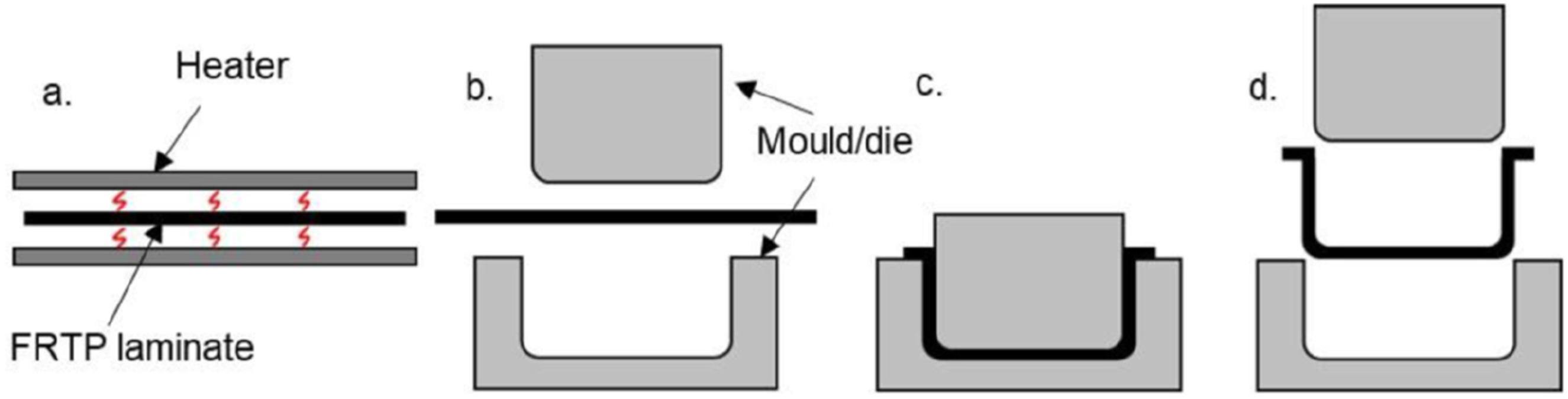
Cooling is an important stage after stamping. After the material is shaped in the tool, pressure must be kept constant as the thermoplastic matrix composite material is cooled and solidified ensuring the part retains the final shape without distortion. The tool is typically designed with cooling channels that adjust the cooling process to avoid residual stress development. This is particularly crucial for high-performance thermoplastics like PEEK where rapid changes in temperature can cause internal stresses that may lead to cracking during service life of the part. The female tool detail of the matched tool is removed and the formed part is demolded from the male tool detail.
Main advantage of the stamp forming process is its speed and efficiency.55,70 Unlike traditional thermoset matrix composite manufacturing processes which require curing and long cycle times stamp forming only includes heating, shaping, and cooling the material. The whole cycle to manufacture thermoplastic composites can be done in under a few minutes. This makes stamp forming effective for mass production in industries where time and cost are critical like aerospace and automotive. 10
However, one challenge is related to the behavior of the composite material during forming. While fibers provide high strength and stiffness, they also restrict flexibility and make achieving complex shapes difficult without defect formation. Intraply shear (shearing within a single ply) and interply slip (slippage between layers) get a crucial role in stamp forming especially in geometries with double curvature. Managing these intraply mechanisms during stamp forming processes is a challenge because UD fiber reinforced laminates are less flexible compared to fabrics reinforced laminates. 43 Fabric reinforced laminates are more flexible due to their woven architecture allowing better adaptability for deformation during forming processes. Interlaced fiber structure in fabrics facilitates intraply shear and reduces internal stresses. This makes them more prone to obtain defects such as misalignment and wrinkling. 71
Combination of intra-ply shear and inter-ply slippage offers deformation with least resistance. Initially, multiple small wrinkles may appear as shown in Figure 3(c) which can follow two potential paths. They might disappear if the deformation mode shifts to a combination of intraply shear and interply as shown in Figure 3(a) or they might evolve into more significant wrinkles if this mode of deformation faces too much resistance as shown in Figure 3(b). Alternatively, when bending resistance is sufficiently low, several smaller wrinkles may form which can be straightened by shear or folding. Laminate deformation behaviors when double curvature leads to excess material during forming.
43
(a) Intraply shear, no wrinkling; (b) Limited intraply shear, wrinkling; (c) Shifted buckled region followed by the first or second path.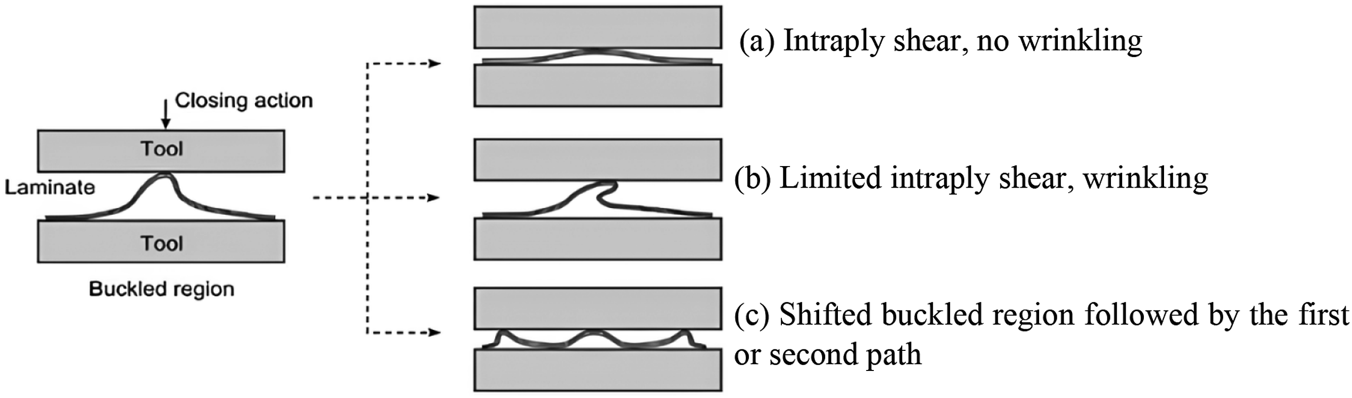
In complex shapes, wrinkling is mostly problematic such as in corners or double-curved surfaces where the composite material is subjected to variable degrees of both tension and compression. 10 Variations in thickness can also occur in complex areas of a part. For instance, during stamping of deep bends or corners fibers may not effectively distribute leading to local thinning or thickening. This can affect both the part’s dimensional accuracy and its structural integrity in the service life of a part. Additionally, residual stresses are obtained when the thermoplastic material is cooled and solidified especially in high-temperature matrices like PEEK. If cooling of the stamping part occurs too rapidly internal stresses can be established leading to warping, cracks, or dimensional distortions. 72
AFP
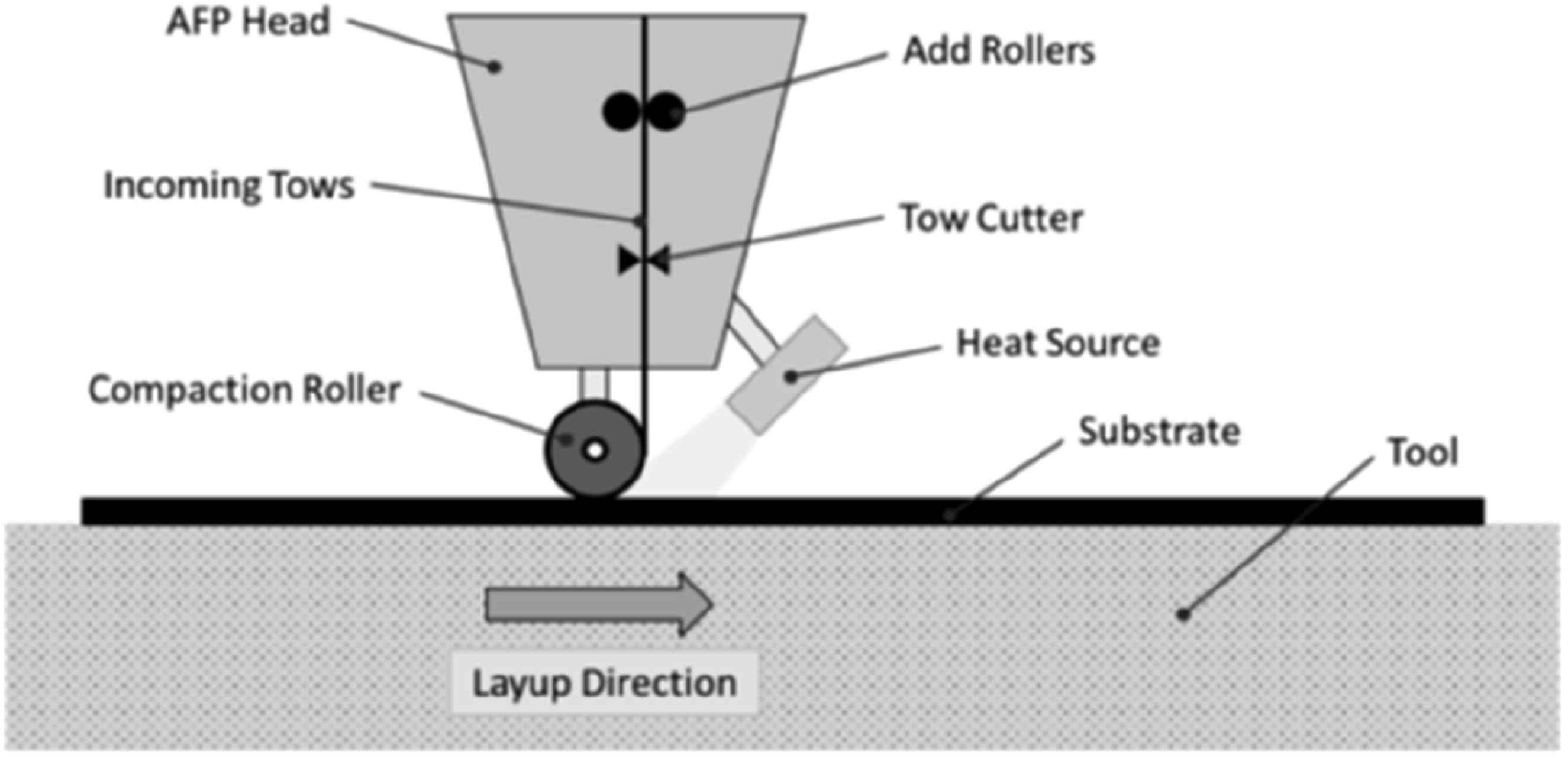
AFP is an innovative manufacturing process widely used in production of thermoplastic and thermoset composites especially in the aerospace industry. AFP utilizes a robotic system to simultaneously lay-up multiple tows of composite materials onto a tool surface which has desired geometry and shape for manufacturing. Each tow consists of fibers embedded in a thermoplastic or thermoset matrix.
11
The schematic view of the AFP process is depicted in Figure 4. Schematic representation of the AFP process.
11

For thermoplastic materials, accurate fiber placement combined with in situ consolidation eliminates the need for traditional autoclave curing allowing faster production cycles.
56
In Figure 5, a schematic representation of the in situ thermoplastic compaction system is presented.
11
Three areas which have different roles for compaction of thermoplastic composites exist in Figure 5. The representation shows the setup of heating and cooling zones in a placement head. It is used for in situ thermoplastic consolidation. The first hot line compactor makes initial contact between the composite material and layer. The second hot area compactor keeps the material warm to strengthen the bond between layers. The third cold compactor cools and solidifies the material reducing gaps and increasing the strength of the layer.
11
Representation of the in situ thermoplastic compaction system.
11
AFP is a highly efficient method for manufacturing lightweight and strong components especially in applications requiring high performance. 50 However, the use of thermoplastic composites in AFP also has certain challenges. The need for high processing temperatures especially for materials like PEEK which must be processed above 350°C is a main challenge for AFP. 11 This requires advanced heating systems and appropriate equipment. Therefore, this makes the whole process more complex and expensive compared to AFP processes for thermoset composites. 56 Additionally, thermoplastic tows are not easily tackled since in contrast they are typically stiffer than thermosets. Thus, this complicates the layup process particularly for parts with complex shapes like ducts or curved skins for an aircraft. 50
However, AFP also offers enhancement of precision in fiber alignment, which is critical for maintaining structural unity and mechanical performance of composite parts. Stated precision is especially important in aerospace applications where a minor defect can be a risk for safety and functionality. 11 As companies try to use more sustainable and efficient manufacturing methods, AFP for thermoplastic composites is expected to play a significant role especially in aerospace industries.50,56
Bonding and welding technologies
Thermoplastic composite welding or bonding are critical for assembly of lightweight and high-performance structures particularly in aerospace and automotive industries.73–75 These processes provide significant advantages over traditional joining techniques such as mechanical fastening and adhesive bonding. This also reduces the need for additional components which lowers overall weight and enhances structural efficiency.76,77
Fusion bonding also called thermal welding involves heating surfaces of thermoplastic composite parts until the composite material reaches its melting point.78–80 This process allows polymer matrix chains to diffuse and bond upon cooling.56,61,81 Softening and re-solidifying of thermoplastic matrix without chemical alteration improves ease of repair and recyclability.56,74,81 Various fusion bonding methods such as hot plate, hot gas, induction, and ultrasonic welding have been developed to optimize joint strength and minimize defects like voids and delamination.36,61
Resistance welding is a process for joining thermoplastic composites especially with embedded conductive materials.74,80,82,83 In this method, placing a heating element, often a metal mesh, carbon fiber, glass fiber, 82 or a nanocomposite79,83 at the interface of parts to be joined is performed. When an electrical current passes through the heating element heat is generated due to resistance.74,80,82–84 In this period, melting the polymer matrix and forming a strong bond takes place under pressure.74,80 Resistance welding has advantages like efficiency and cost-effectiveness particularly in aerospace applications.73,74,82
One of the most common defects in resistance welding is non-bonding at the overlap edge, often caused by insufficient temperature or too much pressure at the interface. Other problems such as voids from trapped air or gas, delamination due to uneven stresses and fiber misalignment can also reduce the strength of the weld. 85 These issues are usually related to uneven heat across the joint and not enough melted polymer flowing into all areas. Ultrasonic-assisted resistance welding (UARW) can be a candidate for a solution. It uses vibration during the final stage of welding to help the polymer spread better and stick more strongly to the other surface. This method increases the bonded area and makes it possible to use lower pressure during welding. 86 Ultrasonic vibrations also allow the polymer chains to move better which helps the melted surfaces join better. 87
Types and shapes of heating elements also affect weld quality. Stainless steel mesh is commonly used, but it sometimes does not bond well to the polymer and can cause current to leak. To fix this, nanocomposite heating elements such as polymer films with carbon nanotubes have been developed. These materials heat more evenly and match better with the thermoplastic matrix. 86 However, some tests showed that even though these joints were stronger, small defects could appear inside the heating layer. This shows that better heating materials still need to be developed to balance electrical performance and mechanical strength. 87
In the aerospace industry, there has been a significant increase in the use of thermoplastic composites enabling manufacturing of large, complex, and lightweight structures. 36 Aircraft components such as wing skins and fuselage sections benefit from welding processes that give strong consistent joints eliminating drawbacks of traditional fasteners. Fasteners can be potential stress concentrations and moisture penetration.56,77 For instance, the Airbus A380-800 has thermoplastic composite parts that were joined using advanced welding methods. 36
Despite the advantages challenges also take place during different types of welding of thermoplastic composites.73,77,81–83,88–90 Trying to control heat distribution is critical to avoid degradation of the polymer matrix and ensure a uniformity in the welding area without defects. During welding, maintaining consistent pressure during the process is vital for high-quality bonding.61,80 Optimizing these parameters and developing automated systems that can deliver uniform, high quality welds at faster production rates are being investigated.56,74,76 Another important disadvantage is the contradiction of thermoplastics with some reinforcements such as glass fibers. Glass fibers are non-conductive material. This makes the use of additional conductive interlayers necessary like carbon or stainless steel meshes. This not only increases manufacturing costs but also complicate the process.91,92 Additionally, environmental parameters such as extreme temperatures or humidity can decrease the strength of thermoplastic welds. During continuous weldment, resistance welding faces challenges including uneven heat distribution, pressure variability and current leakage. Challenges weaken joint quality and integrity. These issues are further complicated by polymer degradation and corrosion in metallic resistive elements. Addressing these problems requires advanced solutions such as surface treatments and nanocomposites. 93 These limitations can make welds less reliable for long-term applications in aerospace or automotive industries.82,92
To evaluate weld integrity and detect internal defects, several non-destructive testing (NDT) techniques can be done. Ultrasonic C-scan inspection is widely applied for mapping voids, delamination or weak bonding areas. Infrared thermography offers a rapid method to detect thermal inconsistencies that indicate structural defects. For detailed internal inspection, X-ray computed tomography (CT) enables visualization of fiber orientation, voids, and bonding quality in three dimensions. 94 These methods are essential with industry standards such as ASTM D1002 for lap shear strength testing and ASTM E2580 for infrared NDT of composites. Implementing NDT protocols is critical for certifying resistance welded joints for structural applications, particularly in safety-critical industries. 93
3D printing
3D printing is a major alternative process to produce thermoplastic composite parts. Fused Filament Fabrication (FFF) has changed composite manufacturing by enabling creation of complex geometries with minimal material waste.66,68 This process involves depositing thermoplastic filaments with reinforcements like carbon fibers layer-by-layer. 68 Compared to conventional methods, FFF offers lower production costs, faster prototyping and better design flexibility while eliminating need for costly tooling.66–68,95 However, challenges such as anisotropic mechanical properties because of the layer-by-layer construction can decrease the performance of 3D-printed parts.67,68
Key advantages of FFF-based 3D printing include ability to produce lightweight, high performance parts tailored for industries like aerospace and automotive.66,67 Additionally, absence of using tools and capability for rapid prototyping facilitate production cycles, reduce lead times, and support sustainable manufacturing practices. This makes FFF a viable alternative to traditional composite production techniques. 67
Tools and fixtures used in manufacturing processes
AFP or hand lay-up tools
In both cases, AFP and hand lay-up, tools are used for the same purpose.96,97 Obtaining proper form, size and shape of the composite part which can be used as skin, rib, or spar for an aircraft is the main purpose since layer by layer production is done with both AFP and hand lay-up processes. 98
Lay-up tools are mainly critical for precision and quality of composite parts. These tools provide a stable surface which fiber tows or tapes are placed. The surface helps to achieve consistent alignment and support the material during the in situ consolidation process.42,99 Layup tools must be highly resistant to high temperatures and pressures, which is required for bonding thermoplastic fibers. Therefore, they must preserve their shape without deformation throughout entire and long term AFP processes.
100
By maintaining a stable form layup tools prevent misalignment and ensure uniform layer consolidation.
101
In Figure 6, examples of AFP tools are shown. Example of AFP tools.
11
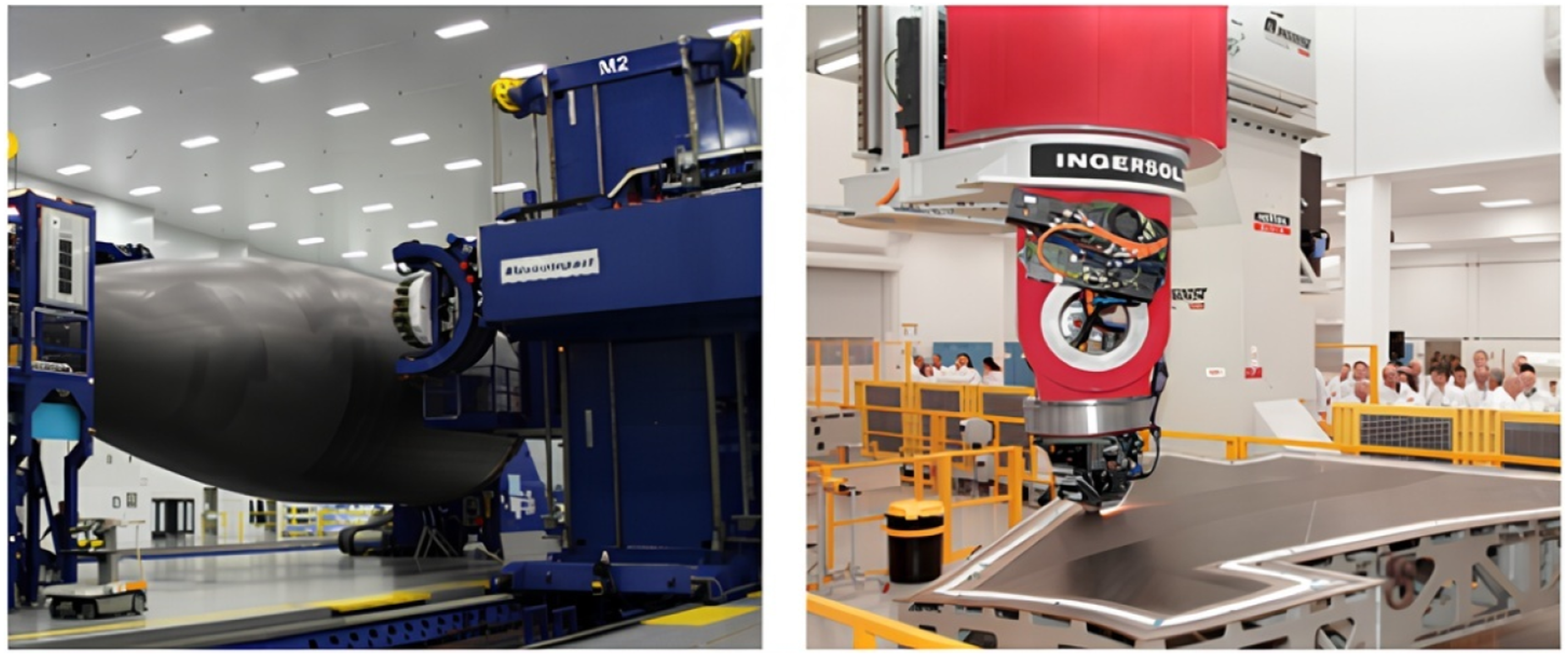
In addition to providing stability, advanced layup tools are often equipped with heating and cooling elements to arrange the temperature profile of the lay-up tool during fiber placement process. 65 Controlled heating is essential to provide that thermoplastic resin reaches its melting point which allows it to bond effectively. 102 Common heating sources integrated into the tool system allow for precise temperature control and help minimize issues like thermal gradients, which could lead to warping or deformation of the composite part. 103 Remarkably, adaptability of layup tools to control heating makes them urgent for AFP applications particularly in aerospace industries. 104
Stamp forming tools
The stamp-forming process involves preheating a thermoplastic composite laminate and pressing it between matched tools to obtain an appropriate shape and geometry. Afterward, it is followed by cooling and consolidation. Tooling and process parameters in stamp forming are critical to ensure high-quality defect-free parts. The main part of the stamp-forming process is the use of matched tools which are responsible for shaping the heated composite blank into the desired form. Of importance, matched tools give high precision and control over the final part geometry.
43
Materials used for the tools need to overcome high process temperatures and pressures to prevent wear over cycles.
10
In Figure 7, a tool used in stamp forming is shown. The tool is used to produce a U-profile which is also called “bathtub” fabric thermoplastic composite part for experimental investigations.
64
An example of a stamp forming tool.
64
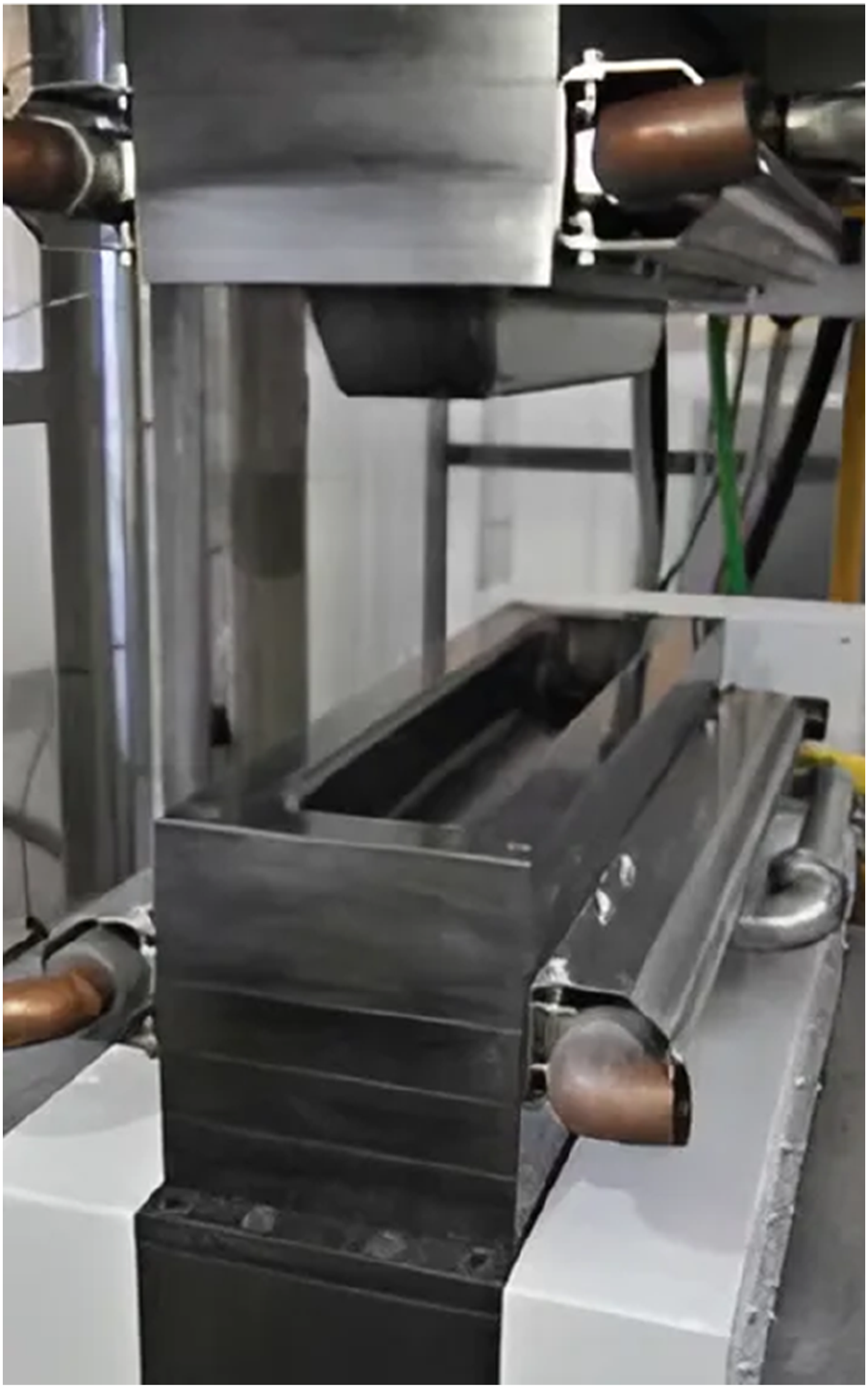
In stamp forming of thermoplastic composites, tools are essential since they influence quality and precision of the final product in correspondence with AFP tools as mentioned in Section 5.1. 105 Tools are typically made from high-strength materials like DM3X which can be capable of resisting elevated temperatures and pressures required.72,106 DM3X (1.2367) is a high-performance hot work tool steel known for its superior high-temperature strength and wear resistance. This makes it ideal for manufacturing tools. Its chromium and molybdenum content provide excellent thermal fatigue resistance and extended tool life.
Hence, tools provide a stable base for shaping thermoplastic materials into complex geometries. The base helps to maintain fiber alignment and reduce the possibility of defect formation such as warping or delamination.107,108 The stability is important as thermoplastics are heated above their melting point and stamped into the desired shape within the tool. This is needed for optimal bonding and mechanical integrity in the final composite part. 109
Welding fixtures
In thermoplastic composite welding processes such as resistance welding and ultrasonic welding tools (fixtures) play a crucial role. Main function of tools is to apply and maintain pressure during heating and cooling stages of the weld ensuring optimal contact between part / assembly surfaces. Tooling materials need to be highly thermally insulating to minimize heat loss allowing thermoplastic to reach its melting point effectively. Materials like ceramics or silicone rubber are commonly used for this purpose, preventing heat from dissipating into the tooling itself which can affect quality of the weld. 74 Design of these fixtures must also ensure even pressure distribution across the weld area critical for achieving uniform molecular diffusion during cooling and to prevent defects such as fiber misalignment or delamination. 61
Process parameters such as pressure, heat application, and time significantly impact performance of the welding tool. For instance, in resistance welding, proper calibration of heating element and pressure applied by the tool ensures that supplied energy leads to even heating at the bond line facilitating adequate fusion of polymer chains. Insufficient pressure or uneven tool alignment can lead to incomplete bonding or weak welds.
73
Moreover, fixtures need to accommodate potential fiber movement during the welding process particularly for complex geometries to prevent misalignment and ensure structural integrity. Therefore, tools designed for thermoplastic welding must be adaptable, capable of handling various material thicknesses and shapes while maintaining uniform pressure and heat application throughout the process.
61
The whole process can be done step by step and the fixture must be adaptive for the step-by-step process. In Figure 8 an exemplary welding fixture and its step-by-step indexes are shown for illustrating purposes. An example of welding fixture.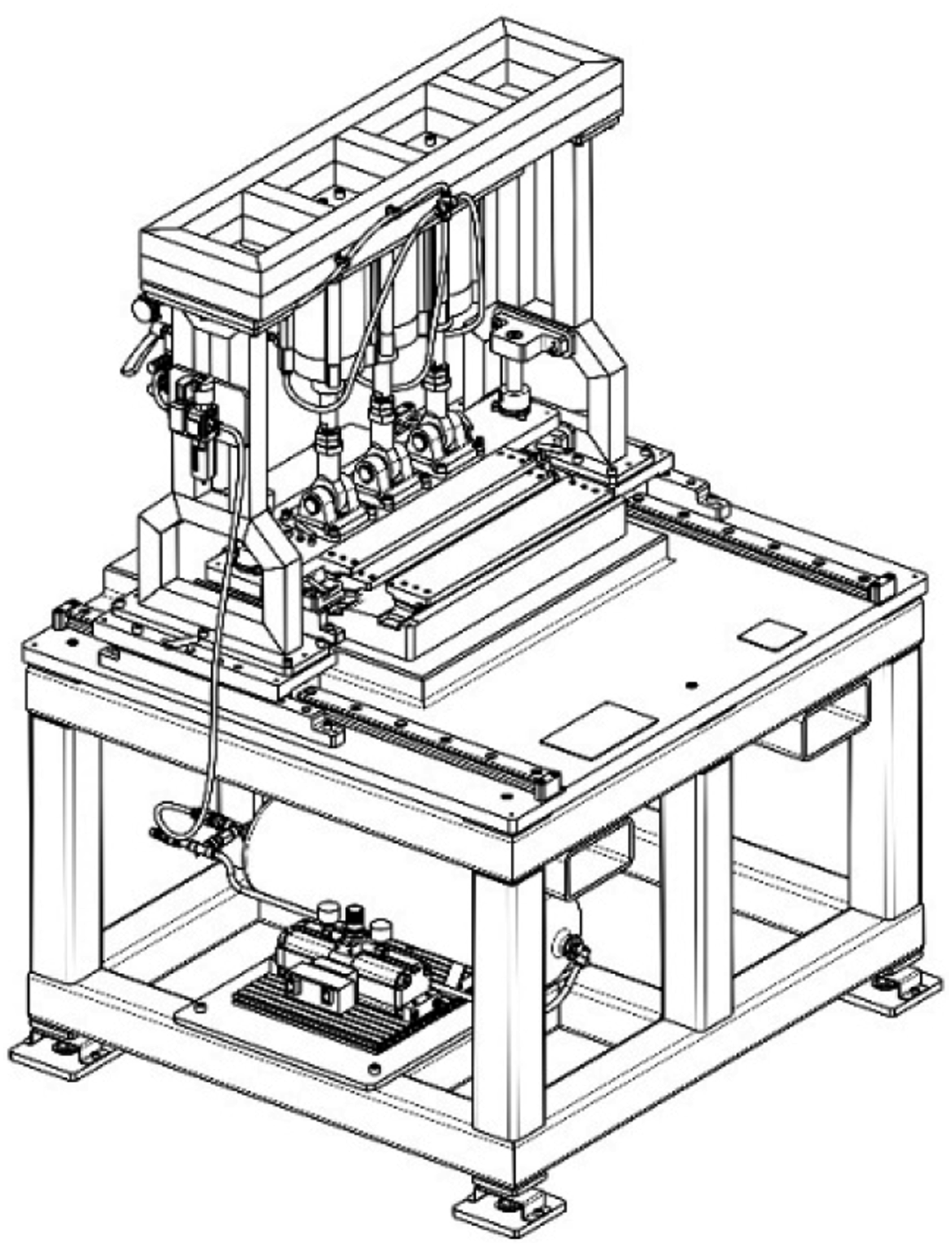
Design stages of tools
Design of tools for thermoplastic composite production is a highly specialized process that involves optimizing several parameters such as thermal properties, structural integrity and material durability. Tool design depends on final geometry of the thermoplastic composite part being produced. In part design the tool surface, which is mostly critical for an aircraft, must be determined. For instance, if the composite part is a skin detail of an aircraft the tool surface can be an aerodynamic surface which must be certainly more precise. Thus, tools are designed mostly based on tool surface geometry of thermoplastic composite parts. The tolerance of tools is generally given one-third of the tolerance of the part to be manufactured. Keeping the tool’s tolerance minimal helps to minimize potential errors during production and allows for accurate part creation. This ratio is preferred to guarantee functional and dimensional accuracy of the part. On the other hand, it is also preferred to manufacture accurate tools. If the tolerances are narrower than one-third, tool manufacturability becomes challenging and unaffordable.
One of the most critical considerations in tooling design is the coefficient of thermal expansion (CTE) as mismatches between tooling material and composite can lead to deformation, residual stresses, and dimensional inaccuracies during thermal cycles. As thermoplastics are heated they melt and expand. During the cooling phase they contract and solidify. Failure to account for these thermal fluctuations can result in dimensional inaccuracies in the final part. To reduce this tool designs must include a stage known as scaling. This involves adjusting tools to accommodate expected expansion and contraction of thermoplastic material. By applying scaling tools are calibrated to ensure that the part achieves its intended final dimensions after the cooling and solidification process. Scaling is applied to the center of gravity of the part. The scaled part is the main reference of the tool design and surfaces of the tool are formed from this scaled part.
Materials like aluminum and steel while commonly used due to their strength tend to have higher CTEs compared to composite materials leading to issues like warping and spring-in effects. As a result, Invar, a nickel–iron alloy with an exceptionally low CTE, is often the preferred choice for high-precision applications like aerospace, where dimensional stability is crucial. Invar’s ability to closely match the CTE of composite materials ensures minimal deformation during the curing process.63,110,111
Finally, cost and machinability of tooling materials are also significant factors in the design process. While Invar provides the best precision and lowest CTE it is expensive and difficult to machine which limits its use in some industries. Tool steels like DM3X, 1.2365 and aluminum are easier to machine and less expensive, but their higher CTE makes them less suitable for high-precision applications. Composite-based tools such as those made from carbon fiber-reinforced plastics offer a good balance between cost, weight, and thermal performance but they may not have the same durability as metal tools. The decision to use a particular material depends on specific requirements of the composite part being produced, expected production volume and level of precision needed.63,110,111
AFP or hand lay-up tool design
Manufacturing process parameters for both AFP and hand lay-up play a crucial role in tool design. In both methods, vacuum bagging or similar techniques are employed to ensure proper compaction between fibers and thermoplastic composite layers as well as between each layer. This ensures that fibers remain in their designated positions without detaching from the tool. To maintain the integrity of the vacuum system it is essential that no vacuum leakage occurs. Therefore, tool designs must adhere to strict criteria regarding leakage prevention. For instance, any holes in the tool must be blind and sharp edges should be avoided to prevent vacuum bag rupture. Sufficient space must also be allocated for vacuum ports and seals to create an effective vacuum bag which is used to evacuate air and excess resin from the composite part. Additionally, since AFP processes often involve high temperatures tools must be resistant to heat. Thus, many setups include integrated heating systems to maintain a consistent temperature throughout the process. 38 Therefore, a heater is placed under tools. Efficient placement is crucial to obtain better heat circulation and keep temperature constant. On the other hand, transportation requirements, other processes before and after AFP or hand lay-up are other critic parameters for tool design.
In Figure 9 design of an AFP tool is shown whole stated criteria are parameters for this design. Desired part manufacturing can be done with this tool. AFP lay-up tool drawing.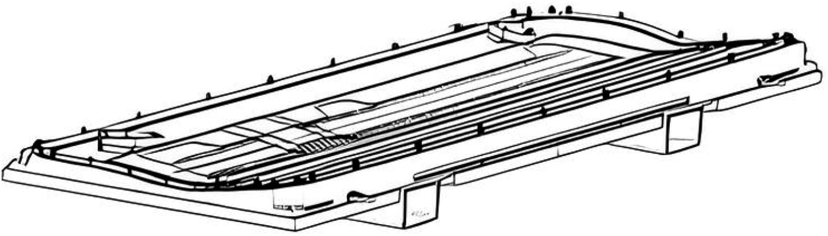
Stamp forming tool design
Tools for stamp forming need to be matched between female and male tools as shown in Figure 10. This is a crucial criterion. If there is a mismatch between tools stamping process cannot be done properly and the part will be scrapped or reshaped. Remarkably, in aerospace, recyclability is an advantage of thermoplastic composite materials.
24
Correspondingly, in tool design, tool details must be designed to provide alignment and coordination of these two female and male tools. Stamp forming tool drawing and its detail part; (a) press base plates, (b) male tool, (c) female tool, and (d) tool details for coordination.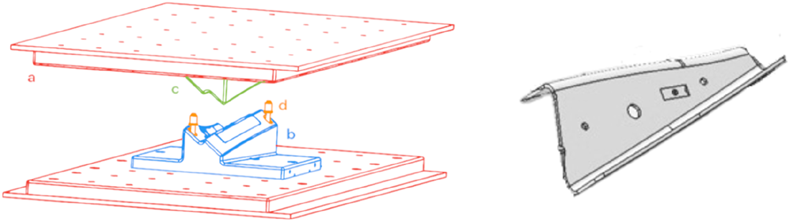
In analogy with AFP tool design stages scaling must be applied to the stamp forming tool design. After scaling and designing both female and male tools coordination details must be added to the tool design. Also, the bases of the press machine must be coordinated with the tool to prevent misalignment of stamp forming.
Tools in stamp forming are also designed to manage heat distribution effectively ensuring the composite reaches ideal temperature for formability and then cools evenly to solidify structure without inducing residual stresses.112,113 Tools with embedded heating and cooling channels allow for precise temperature control.114,115 For semi-crystalline thermoplastics, the rate of cooling is particularly influential as it affects crystallinity and mechanical properties of the final component.116,117 This level of control is essential for applications such as in aerospace and automotive industries.71,118
Design of cooling channels in hot stamping tools plays a critical role in ensuring effective heat transfer, uniform mechanical properties, and efficient cycle times. Traditional straight drilled channels are widely used due to their simplicity and ease of machining, but they often fail to deliver sufficient cooling in tools with complex geometries. These channels cannot follow surface contours closely. This leads to uneven temperature distributions and localized overheating. 119
To overcome these limitations, conformal cooling channels have been introduced. These channels are produced using additive manufacturing and can be designed to follow the tool surface more precisely. As a result, they offer more efficient heat extraction, reduced thermal gradients, and better control over the cooling process. 119 When properly designed, conformal channels significantly reduce cycle time by allowing higher cooling rates. For example, in tools where uniform hardness and reduced warpage are critical, conformal cooling ensures a more consistent quenching effect across the entire part surface. 120 The ability to place channels closer to the tool surface increases the cooling rate. 121
Among conformal designs, several geometries have been studied. Longitudinal, transversal, serpentine, and parallel layouts offer different benefits. Comparative computational fluid dynamics (CFD) simulations showed that longitudinal conformal cooling channels exhibit superior cooling efficiency at higher Reynolds numbers due to their ability to maintain low average and maximum tool surface temperatures. Serpentine channels on the other hand, perform better at lower Reynolds numbers due to increased fluid contact time, which enhances local heat transfer. 122
Another approach is using fractal cooling channels. These are designed using principles of fractal geometry and branching networks. Fractal channels distribute coolant uniformly minimizing thermal gradients and improving part quality. Experimental studies showed that fractal channels reduced average blank temperature by 22% and improved temperature uniformity by 39% compared to traditional straight channels. Additionally, they resulted in a 34% increase in daily production rate. 123
Despite their advantages, conformal and fractal channels require complex manufacturing processes usually involving metal additive manufacturing which increases production costs. Therefore, their application is most justifiable in high volume or performance parts where cooling efficiency significantly influences product quality and throughput.119,120
Moreover, effective stamp forming needs tools that can handle high-speed operations while maintaining even pressure and temperature.107,115 Advanced simulation tools including finite element analysis (FEA) are frequently used to optimize tool designs and predict process outcome parameters such as fiber reorientation, thickness uniformity, and residual stress. 124
Resistant welding fixture design
In resistance welding, welding fixtures are essential to obtain accurate alignment, consistent pressure application and optimal thermal conditions during the process. Also, an electrically resistive heating element is placed between thermoplastic parts to be joined. 74 Effective fixture design ensures that components are held in place with uniform pressure facilitating intimate contact and efficient heat distribution across the weld area. A well-designed resistance welding fixture must address these factors.
In resistance welding tools, an assembly process can involve multiple steps due to the presence of several parts within the structure. Each step requires specifically designed tool detail which consists of distinct indexing holes that are used as alignment references. These indexing holes have an important role in ensuring precise positioning of parts before the welding process begins. In Figure 11, index holes, steps, and tool details of a resistance welding fixture are particularly given in a drawing of tool design. The alignment process prevents any potential displacement of parts during welding. The tool design must be done accurately to accommodate geometry, material properties, and tolerances of parts. Additionally, tool design must consider welding parameters such as heat input, clamping forces, and electrode positioning.
93
Exemplary welding fixture tool drawing.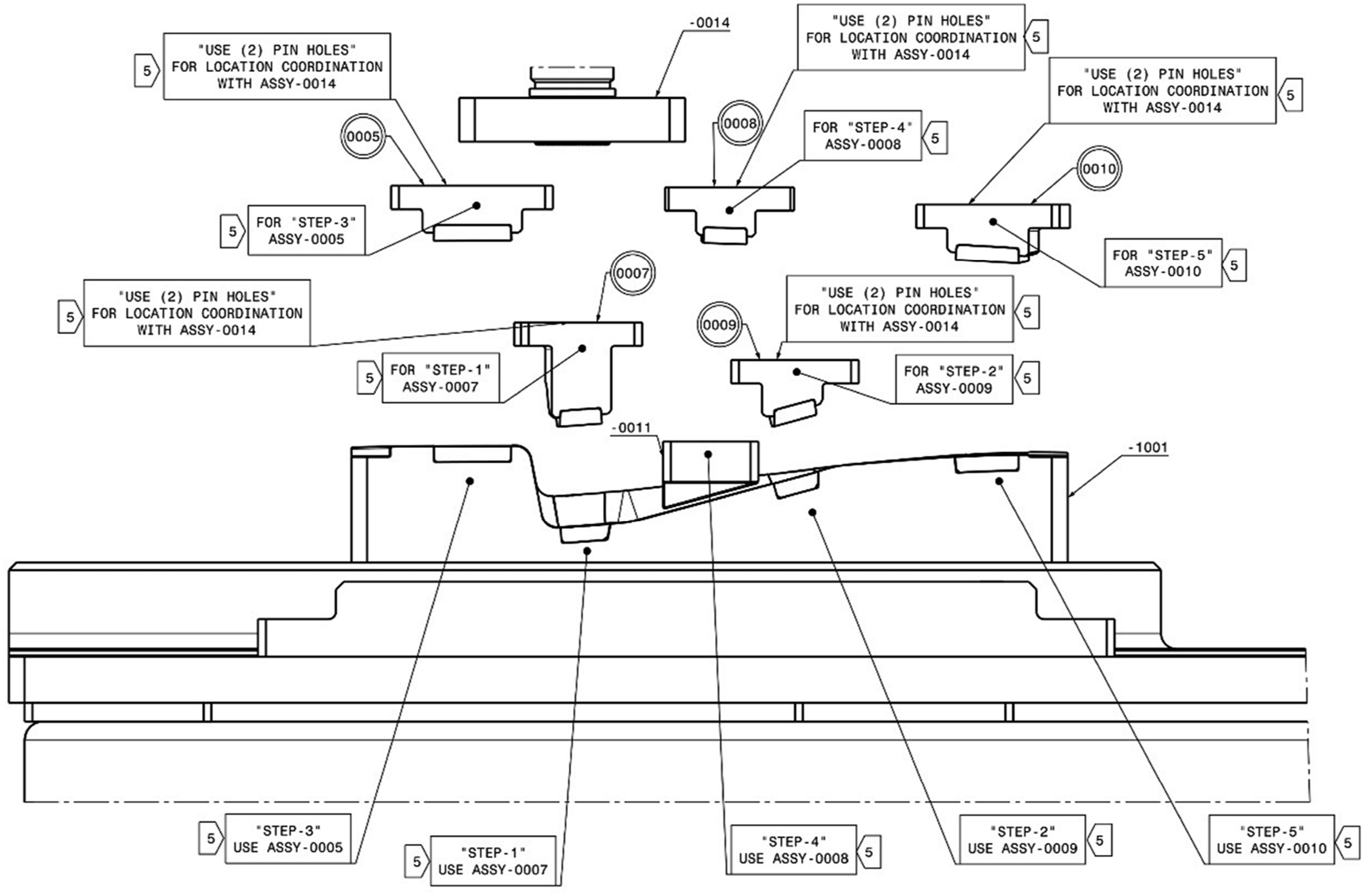
On the other hand, inconsistent pressure can lead to defects such as voids and incomplete bonding. This may compromise mechanical performance of the joint. For instance, fixtures designed for resistance welding should allow precise clamping and pressure control to ensure even heating across the weld interface. 84 In Figure 11, clamping and pressure are provided with tool details. Additionally, the fixture should integrate features to monitor temperature as uniform heating is vital to avoid localized overheating or insufficient melting. 125
The design of resistance welding fixtures should also take into account properties of the thermoplastic materials being used such as melting temperature and thermal conductivity. These factors determine how heat is applied and controlled throughout the process. For instance, maintaining thermal uniformity can be a challenge especially when working with larger components. Therefore, the fixture should be designed to minimize heat loss and ensure even distribution across the heating element. 61 By optimizing these aspects, it can be ensured that resistance welding provides strong, durable joints suitable for demanding applications such as aerospace and automotive industries. 74
Manufacturing stage of tools
Metallic tool manufacturing involves advanced material selections, machining, surface treatments, and inspections to create durable and appropriate tools. The process begins with careful selection of materials like tool steel (DM3X), invar or aluminum alloys which are chosen for their mechanical strength, thermal resistance, and adaptability to machining processes.126,127 These materials are typically shaped into near-net forms through casting or forging that provide a solid for machining operations.126,127
Selection of tooling materials such as DM3X, invar, and aluminum alloys depends mainly on their mechanical strength, thermal resistance, and machinability. DM3X is a high performance stainless tool steel known for its excellent strength and durability. It can maintain dimensional stability and surface quality during thermoforming processes of thermoplastic composites such as polyetherketoneketone (PEKK). 13 In comparison, invar is widely used for its extremely low thermal expansion. However, it is heavy, expensive, and difficult to machine. On the other hand, aluminum alloys are lightweight and very easy to machine, although they cannot maintain shape as well at high temperatures. 63 From a performance optimization perspective, each of these materials offers specific advantages depending on tooling requirements. Invar remains the preferred choice for applications that demand high dimensional accuracy under thermal cycling. 63 DM3X, due to its balance of mechanical strength and moderate thermal expansion, is well-suited for stamp forming tools used in rapid production environments. 13 Meanwhile, aluminum alloys are best used in low temperature or prototype tooling. 63
After material selection, manufacturing process selection can be done according to requirements and relevant properties. Primary machining methods include high-speed machining (HSM) and electrical discharge machining (EDM). 111 HSM offers precision and speed particularly in creating intricate geometries by utilizing advanced computer numerical control (CNC) technology. EDM, on the other hand, is indispensable for achieving deep and narrow cavities that are difficult to machine conventionally.126,128 Additionally, additive manufacturing techniques such as powder bed fusion have revolutionized the field by enabling integration of features like cooling channels directly into the tool structure. This enhances thermal management and reduces production cycle times.129,130
After machining, surface finishing processes refine tool’s performance and extend its lifespan. Polishing is a critical step to achieve smooth surfaces required for applications such as injection molding, where surface quality directly affects the final product.128,130
Composite lay-up tooling especially for aerospace applications has been produced in many years. Common material for composite tools is carbon-fiber-reinforced polymers (CFRP) which is chosen for their low CTE to minimize dimensional fluctuation during temperature fluctuations. Also, composite lay-up tools are designed and manufactured to ensure proper resin distribution reducing risk of resin starvation. Composite lay-up tool manufacturing process involves creating a master tool followed by lay-up of composite prepregs curing in autoclaves and final machining or sanding. Advanced composite tooling resin materials like bismaleimide (BMI) resin systems offer higher thermal resistance and longer service lives. 63
Quality control and inspection ensure tools are appropriate for design specifications and requirements. Coordinate-measuring machines (CMMs) and laser trackers, which are highly precise machines, are used to measure dimensional accuracy and properties.126,127 Surface profilometers measures roughness of machined parts to ensure desired roughness values.128,129 Functional testing can be conducted under operational conditions to evaluate tool’s ability. Functional testing shows performance of tools to withstand mechanical and thermal stresses during production cycles.127,129,130
Design and manufacturing processes are supported by advanced software tools. Computer-aided design (CAD) software such as CATIA and NX facilitate precise tool design while computer-aided manufacturing (CAM) software optimizes cutting tool paths for efficient machining.126,130,131 Simulation tools like Ansys and Abaqus FEA predict material behavior, stress distribution, and potential failure points.126,128,130 This combination of design and manufacturing not only reduces lead times but also increases overall production efficiency.126,128,131
Process simulation plays a critical role in the development and optimization of tooling for thermoplastic composite manufacturing. FEA and CFD are essential tools for modeling mechanical, thermal, and flow behaviors during forming, placement and welding stages. These simulations allow to predict stress distributions, fiber orientations, temperature gradients, and cooling behavior, all of which directly affect product quality and cycle efficiency.
In the context of stamp forming, process simulation is used to analyze laminate deformation modes such as intraply shear and interply slip. These factors are essential for preventing defects like wrinkling, fiber misalignment, or delamination. Advanced models can simulate the effect of forming parameters, that is, blank temperature, press velocity, and tool cooling rate, on part thickness and fiber orientation. This helps to identify optimal process windows and minimize physical prototyping.
For AFP, simulation tools are used to model interaction between heat, pressure, and consolidation behavior during in situ processing. Thermal-structural coupling simulations predict how temperature and compaction affect void content and interlaminar bonding. These models can also help in optimizing placement head design, heater settings, and tow paths to reduce defects and improve throughput.
Tool designers increasingly use process simulation to validate tool material compatibility, evaluate thermal cycling effects, and predict dimensional shifts due to CTE mismatch. Software like Ansys, Abaqus FEA, Moldflow, or PAM-FORM allow integration of geometry, materials, and boundary conditions for multiphysics analysis. These simulations not only reduce development costs but also ensure that tools meet aerospace grade precision and reliability standards.
Literature research
Thermal analysis plays a vital role in optimizing manufacturing processes for thermoplastic composites, particularly in tool dependent techniques like AFP and stamp forming. While prior sections discussed the importance of tool design, this section focuses on how thermal modeling and simulation influence the performance and integrity of tooling and processes in composite part production.
A key aspect of tool design for thermoplastic composite processing lies in achieving uniform thermal distribution. For AFP, precise in situ consolidation requires consistent heating and cooling cycles across complex tool geometries. Non-uniform thermal gradients can cause defects such as incomplete bonding, fiber misalignment, or internal stresses. Similarly, in stamp forming rapid heating above the polymer’s melting point followed by controlled cooling is essential for defect-free molding. Poorly designed thermal systems can lead to warping, localized shrinkage, or delamination due to uneven solidification or residual thermal stress.
Numerical tools such as FEA and CFD are frequently applied in modeling these thermal effects. However, most thermal studies in literature focus on general polymer processing techniques, that is, extrusion, pultrusion, and injection molding, while only a few target specific requirements of high performance thermoplastic composites in AFP or stamp forming applications.
Design of polymer extrusion dies were investigated in the literature using FEA and CFD. 132 In this study, COMSOL Multiphysics software is used to analyze flow and temperature distribution for high-density PE extrusion. Main interest of this study was optimizing extrusion for pipes made of high-density polyethylene (HDPE). Focusing on modeling pressure, temperature, speed, and viscosity within the tool ensured homogeneous flow and minimized defects that could occur in the final product. Thermal analysis, secondary to pressure and flow optimization is important for evaluating temperature variations caused by viscous dissipation. Adiabatic conditions were assumed throughout the extrusion process to simplify thermal analysis. Volumetric flow rate of polymer melt was modeled using the power-law model for non-Newtonian fluids. Analysis was conducted under steady state conditions focusing on pressure and temperature distributions within the die. Additionally, isotropic material properties were assumed for die material, which was selected as IMPAX steel ensuring uniform heat transfer behavior in simulations. Simulation results show that extrusion die design can achieve a temperature increase of only 1.53 K, which represents minimum thermal effect on flow properties. The study highlighted importance of thermal analysis in ensuring mechanical integrity of the tool particularly in terms of how spider legs withstand pressure. 132
A pultrusion die was built up to manufacture thermoplastic composite filaments made of carbon fiber and PP for application of additive manufacturing in another study. 133 Here, heating and cooling inside the tool were analyzed using finite element modeling (FEM) to ensure that filaments were produced under homogeneous thermal conditions. The analysis assumed homogeneous thermal properties and uniform heat generation from resistive heating elements. Also, channels for water cooling were assumed to provide consistent and uniform cooling across the die. The study also included steady state and transient thermal analyses to examine heating behavior under changing pulling speeds and initial temperature conditions. Thermal analysis was crucial to prevent void formation and ensure a uniform filament diameter. Heating elements were controlled by proportional-integral-derivative (PID) controllers while water circulation channels provided cooling. Thermal controls allowed for precise adjustment of die’s temperature during manufacturing, which was essential to maintain desired mechanical properties of filaments. 133
Thermal behavior modeling for superplastic forming tools is focused on in another study. 134 To maintain thermal stability throughout manufacturing process the study simulated heat transfer within forming dies using FEA. The analysis assumed isotropic and homogeneous material properties for tools. This simplifies representation of heat transfer within the tool. For thermal conditions, steady state was applied to evaluate temperature distribution effectively. Uniform heat input was assumed which neglects localized temperature changes caused by tool geometry or boundary conditions. This study highlighted the importance of controlling thermal gradients to prevent die deformation and maintain part accuracy in forming processes within high temperatures. Although this study was more focused on metal forming than thermoplastics, principles of thermal management can be relevant to thermoplastic die design and thermal analysis. 134
Another research investigated analytical and computational models for warm forming die design. 135 Research was directed to the lack of particular studies on thermal stability of warm forming dies. A method that simplified complex boundary conditions of warm forming dies by using one-dimensional heat transfer coefficients (HTCs) was produced. By FEA which optimized temperature distribution in the tool the model was confirmed. In this study, custom FEA code was developed to model thermal distribution in warm forming dies. This code was used to optimize steady state thermal conditions within the die. The analysis assumed one-dimensional heat transfer coefficients (HTCs) to represent complex boundary conditions. This reduces complexity of the model. Steady state thermal conditions were applied to simplify simulation of heat distribution across the die. The study also applied energy conservation principles to calculate heat losses and optimize thermal distribution within the die. Constant thermal properties were assumed for die materials. This study can be relevant to thermoplastic processes which must maintain a uniform temperature throughout the die for product quality. Temperature variations can lead to warpage or uneven cooling. 135
Designing and analyzing self-heating tools using large-scale additive manufacturing for out of autoclave applications is another key research in the literature. 136 The study focused on embedded heating elements within fiber reinforced composite tools to eliminate need for external ovens. In this study, thermal analysis was crucial for determining optimal wire placement and heat flux density to get uniform heating across the tool. Abaqus FEA software was used for thermal analysis. Constant thermal properties were assumed for all materials. Heat flux density from embedded wires was considered uniform along their lengths which simplifies modeling of heat distribution. Additionally, no heat losses were assumed outside of tool’s insulation layers focusing analysis on internal heat transfer dynamics. Thermal analysis primarily evaluated steady-state conditions to ensure temperature uniformity across tool surface. By using numerical simulations and assumptions researchers were able to optimize tool’s thermal behavior. 136
In another study, thermal analysis was used for a plastic injection tool which is designed to eliminate or decrease warpage in the final product. 137 FEA was used to model thermal residual stress caused by uneven cooling during the injection molding process. In this study, NX and LUSAS software were used for tool design and thermal analysis. LUSAS was used for analyzing thermal residual stresses. Results show that more shrinkage occurs in regions close to cooling channels due to rapid cooling which led to warpage in the molded part. The study assumed uniform material properties for both tool and injected polymer. Steady-state thermal conditions were applied during the cooling stage to model temperature distribution effectively. Cooling effect was considered more significant near cooling channels. Additionally, the thermal residual stress field was calculated under the assumption that external heat losses occurred only through tool material and cooling channels. Thus, the importance of optimizing the cooling system to minimize thermal stress in injection tools and improve part quality is emphasized. 137
A research was conducted for designing and analyzing a multi-cavity tool for elastomer injection molding. 138 The study aimed to increase energy efficiency by reducing heated mass of the tool and insulating it to minimize heat loss. Thermal analysis was accomplished to define temperature variations across tool surface and cavities. Independent control zones were assumed to operate uniformly enabling precise temperature control near molding cavities. Thermal insulation between regulated channel block and tool was assumed to be ideal. This minimizes heat loss and focuses energy on critical regions. Uniform heating across tool surface was assumed and simplified thermal balance calculations. Additionally, isotropic material properties were used in the analysis to model heat transfer behavior accurately. Results show that better thermal insulation and use of independent control zones can decrease energy consumption. 138
Different thermal analyses can be applied to thermoplastic forming tools to ensure accurate temperature control, process stability, and part quality. Thermal conductivity measurements help to evaluate how effectively heat spreads within the tool, providing an idea about heater placement and improving thermal uniformity. 136 , 138 Finite element simulations enable engineers to predict local overheating or cooling issues and to optimize tool geometry. 137
However, although these studies offer valuable insight, they often simplify or omit key variables like interfacial heat transfer coefficients, transient temperature evolution, or material anisotropy. Factors that are particularly critical in AFP and stamp forming of continuous fiber composites.
In processes such as stamp forming, tools with embedded conformal or fractal cooling channels significantly affect cycle time and dimensional accuracy. Studies on tool cooling design show that optimized channel geometry improves thermal uniformity and reduces defects. 137 Yet, these advanced thermal control techniques remain underexplored for thermoplastic forming of aerospace grade composites like PEEK or PPS. Moreover, few studies assess how these thermal mechanisms influence crystallization kinetics, fiber resin interaction or stress accumulation during tool part separation.
Similarly, in AFP, temperature gradients along compaction roller or placement head can cause inconsistent consolidation. Thermal simulations in AFP setups are crucial for predicting bonding strength, tow deformation, and internal void formation. These simulations should include dynamic boundary conditions and heat flux exchange with the tool surface which are areas not extensively modeled in current literature.
The CTE must also be analyzed to estimate dimensional mismatch and internal stress due to temperature variation.134,135 In addition, thermal balance studies can support energy efficient tool designs by reducing heated mass and focusing energy input on critical regions. 138 Collectively, these analyses offer essential predictions into tool behavior and give improvements in design, material selection, and process integration for thermoplastic composite manufacturing. Mentioned thermal analyses have not been conducted for thermoplastic stamp forming and AFP tools in the current literature. There is a research gap that needs to be addressed. Applying these analyses to AFP and stamp forming tools would significantly benefit process control, part quality, and tool longevity.
Conclusions
This review article focuses on properties of thermoplastics, their composite characteristics, composite manufacturing processes and tools used in specific processes. It also addresses design and manufacturing considerations of these tools. Furthermore, the article includes a literature review on thermal analysis for tooling in various processes. Through the analysis of existing literature, it is obvious that control of thermal parameters is a crucial factor in ensuring efficiency and quality of thermoplastic composite processing. Studies covering extrusion, pultrusion, injection molding, and additive manufacturing processes emphasize the role of thermal modeling, design optimization, maintaining uniform temperature distribution and improving energy efficiency.
Different tools were analyzed using FEA and CFD to model heat transfer, pressure, and flow distributions. Combination of heating elements, cooling channels, and insulation systems demonstrated the importance of precise thermal control for preventing deformation, void formation, and warpage. These studies highlight how thermal analysis ensures mechanical integrity, optimizes process performance, and enhances tool durability. Additionally, different assumptions such as isotropic and homogeneous material properties, adiabatic conditions, and simplified boundary constraints were frequently adapted to thermal models and simulations. These assumptions simplify calculations and thermal analysis.
However, on the other hand, a significant gap remains in the literature regarding specific thermal analysis for AFP and stamp forming tools. Lack of detailed studies on these processes limit the ability to optimize their tooling designs, thermal performance, and production outputs. Both AFP and stamp forming introduce unique thermal challenges due to localized heating, rapid cooling cycles, and complex geometries, which necessitate more focused research efforts to address these issues. Absence of detailed thermal analysis studies for these tooling methods highlights a need for further research to address challenges related to thermal consistency, cooling rates and overall tool performance.
In summary, while significant progress has been made in understanding thermoplastic properties and manufacturing processes, this review identifies critical gaps in thermal analysis for thermoplastic composite production tools, especially AFP and stamp forming tools. Addressing these gaps through further research will be key to improving efficiency of thermoplastic composite manufacturing.
Footnotes
Declaration of conflicting interests
The author(s) declared no potential conflicts of interest with respect to the research, authorship, and/or publication of this article.
Funding
The author(s) received no financial support for the research, authorship, and/or publication of this article.
Data Availability Statement
Data sharing not applicable to this article as no datasets were generated or analyzed during the current study.