
Abstract
The stamp forming of a woven composite with thermoplastic matrix was investigated in this study. A mesoscale finite element model of a unit cell of a 2 × 2 twill weave of pre-impregnated tows was used to estimate the effective in-plane shear properties for modeling forming processes and predicting formability. In-plane shear stiffness was shown to be a controlling factor in the formability of unconsolidated textile sheets. The stamp forming of a cone-shaped part was modeled for comparison with the experiments. Results show that the simplified process modeling scheme has the potential to predict issues with wrinkling during die closure. Furthermore, the present work suggests that complex representations of the relatively small fiber direction strains may be unwarranted for this type of process modeling.
Introduction
Considered here is the stamp forming of textile composites that is analogous to matched die sheet metal stamping. For thermoset matrix composites this generally involves forming of dry fiber woven preforms 1 –3 prior to resin infiltration and cure processing. For thermoplastics, preconsolidated flat plate materials can be used, for example Refs 4,5, but require melting prior to forming. Also, fabrics made from commingled thermoplastic polymer fibers within a loose tow can be formed as with dry fiber weaves. 6 Less common is a process where preconsolidated solid tows are woven to create fabric preforms. 7 Fabrics woven from preconsolidated tows are much stiffer than for loose fiber tows and were the subject of the present study.
It is well recognized that due to the relative inextensibility of elastic fibers, the dominant mechanism for in-plane straining necessary for a flat sheet to take on double curved shapes is that of in-plane shearing. This involves relative rotation of initially orthogonal fiber bundles and is referred to in the literature as trellising. The angle changes can be quite large, on the order of 60°. This shear strain facilitates significant effective normal strains in the directions 45° from the original fiber directions. Some studies have examined the fiber direction properties in detail, for example Refs 8 –11, but the normal strains available in those directions (generally about 1–2%) are inconsequential compared to those associated with trellising (20–40%), as to their effect on fabric formability. Thus, trellising behavior has received a lot of attention both experimentally using picture frame and bias extension tests 2 and analytically, for example Refs 11 –13. Resistance to trellising consists of friction and binding between tows and defines the in-plane shear stiffness of the material during forming. This is a limiting factor in formability as it causes in-plane compressive forces that can buckle the sheet and form wrinkles. It has been shown that to capture wrinkles; in numerical simulations of forming, it is necessary to reasonably represent both the in-plane shear stiffness of trellising and the out-of-plane bending stiffness of the preform. 1 It is well known from sheet metal forming technology that the combined effects of draw-in and in-plane strain capacity dominate the formability of a flat sheet of material. Draw-in is the drawing of material from the periphery of the mold into the mold. In doubly curved molds, draw-in is immediately accompanied by wrinkling unless the in-plane normal strains occur to accommodate the transition from planar to three-dimensional (3D) shape. Wrinkling can be delayed by blank holders deployed on the periphery of the mold 14,15 but were not part of this study.
A multiscale material finite element (FE)-modeling approach was adopted here. Properties predicted by microscale models of the consolidated tow material were applied in mesoscale models that simulate the woven preform material at the scale of a tow width using the concept of a periodic unit cell. The mesoscale model represents a balanced 2 × 2 twill weave (Figure 1). Using the mesoscale model, effective in-plane shear properties of the fabric were predicted and used in a forming process (macroscale) model of a cone-shaped part for comparison with experimental forming trials.
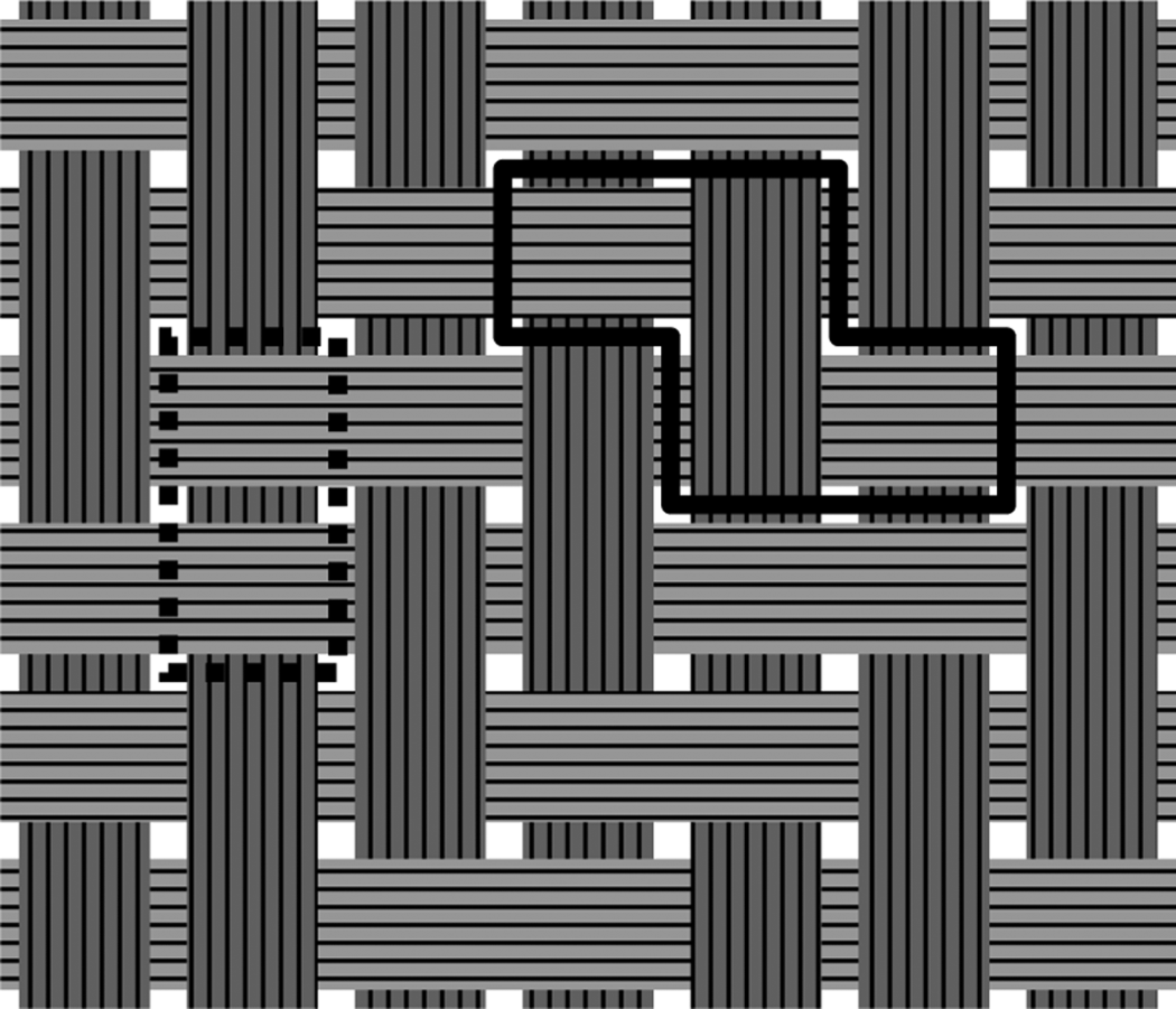
A balanced twill (2 × 2) weave and example periodic unit cells for simple translational periodicity (solid line) and the unit cell applied here (dotted line).
Woven fabric characterization
Material
The polymer pre-impregnated (prepreg) fiber bundles or tows were in the form of a flat tape with an approximately rectangular cross-section. Because the fibers are effectively glued together, the tows and the resulting fabric are markedly stiffer than the dry fiber bundles. This stiffness has a direct effect on the room temperature drape characteristics (formability) of the fabric. This work involved 12k carbon fiber prepreg with polyamide (nylon-6, Capron 8202) woven in a balanced 2 × 2 twill weave.
Shear displacement/strain calculations
Since minimal normal strain can occur in the fiber directions, it must come dominantly from the off-fiber directions as a result of fabric shear as illustrated in Figure 2. During in-plane shear deformation, the gaps between parallel tows close. At some shear angle, the edges make contact and further shearing develops contact compressive forces. Consider Figure 3 where the segments of two warp tows and one fill tow from twill (2/2) fabric are illustrated as taken from the unit cell shown in Figure 1. Figure 3a shows the undeformed fabric and Figure 3b shows the rotated tows and a closing gap between the warp tows. The relation between the shear angle at initial tow contact and the tow width and the gap between parallel tows is:
Fabric in-plane shear (trellis) deformation mechanism illustrating the effective tensile and compressive normal strains that occur. Geometry of tows and kinematics of tow shearing action: (a) initial as woven orthogonal warp and fill tows and (b) after action of in-plane shearing by warp and fill tows rotating an angle θ relative to each other.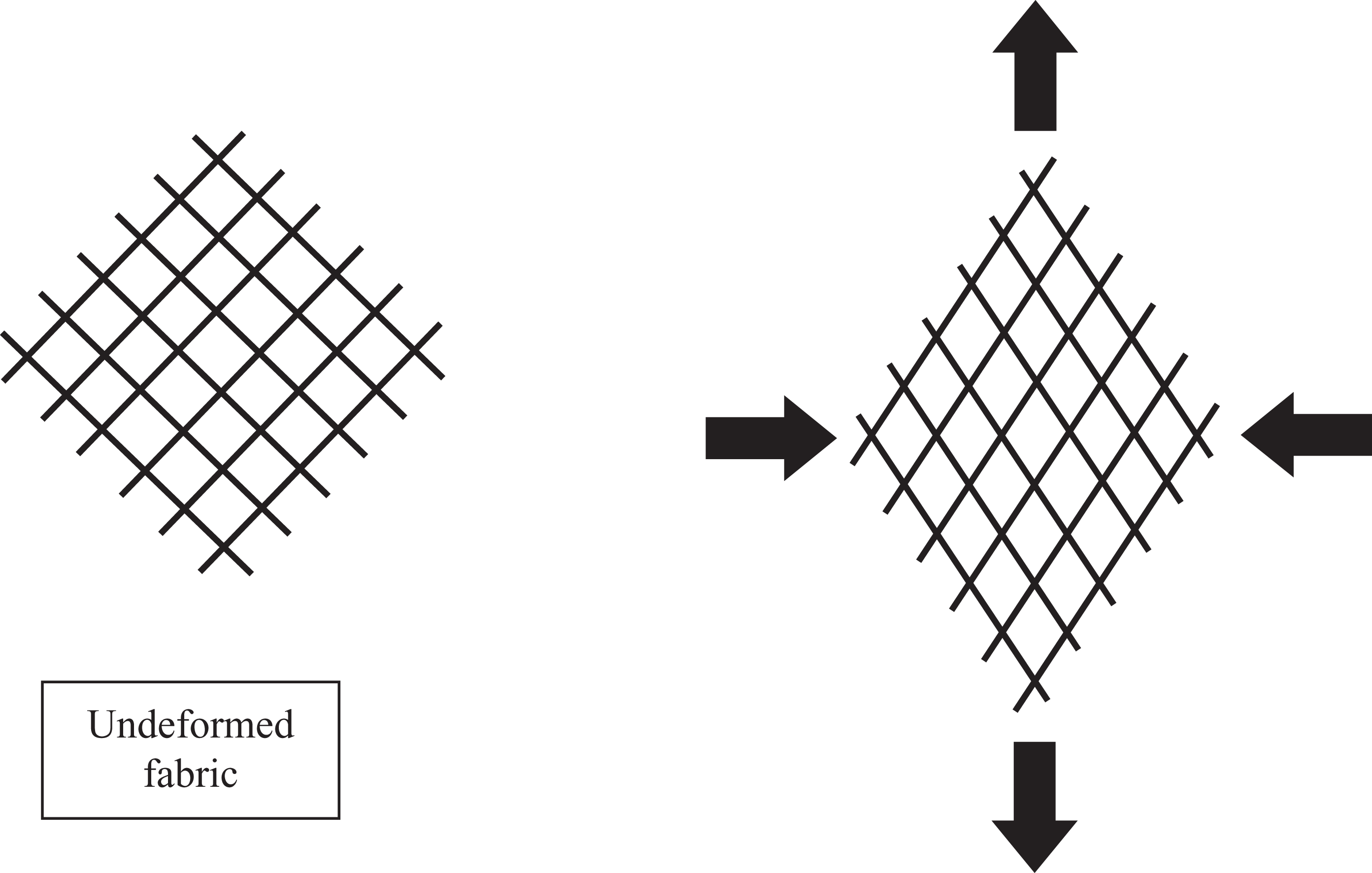
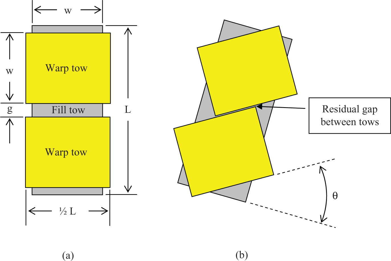

The variables w and g are defined in Figure 3a.
In Figure 4, the geometry of the shearing action is illustrated for the purpose of determining an expression for the effective in-plane normal strains. A material segment of initial length δo at some arbitrary orientation β relative to the original fiber bundle orientation has a length δ after a trellis shear angle θ. Referring to Figure 4, the engineering normal strain at an angle β from the original fiber bundle orientation is given by: Geometry of trellising: (a) original square material element with horizontal and vertical fiber bundles showing material segment of length δo at arbitrary orientation β and (b) ‘sheared’ material element with trellis angle θ and shortened material segment δ at angle β.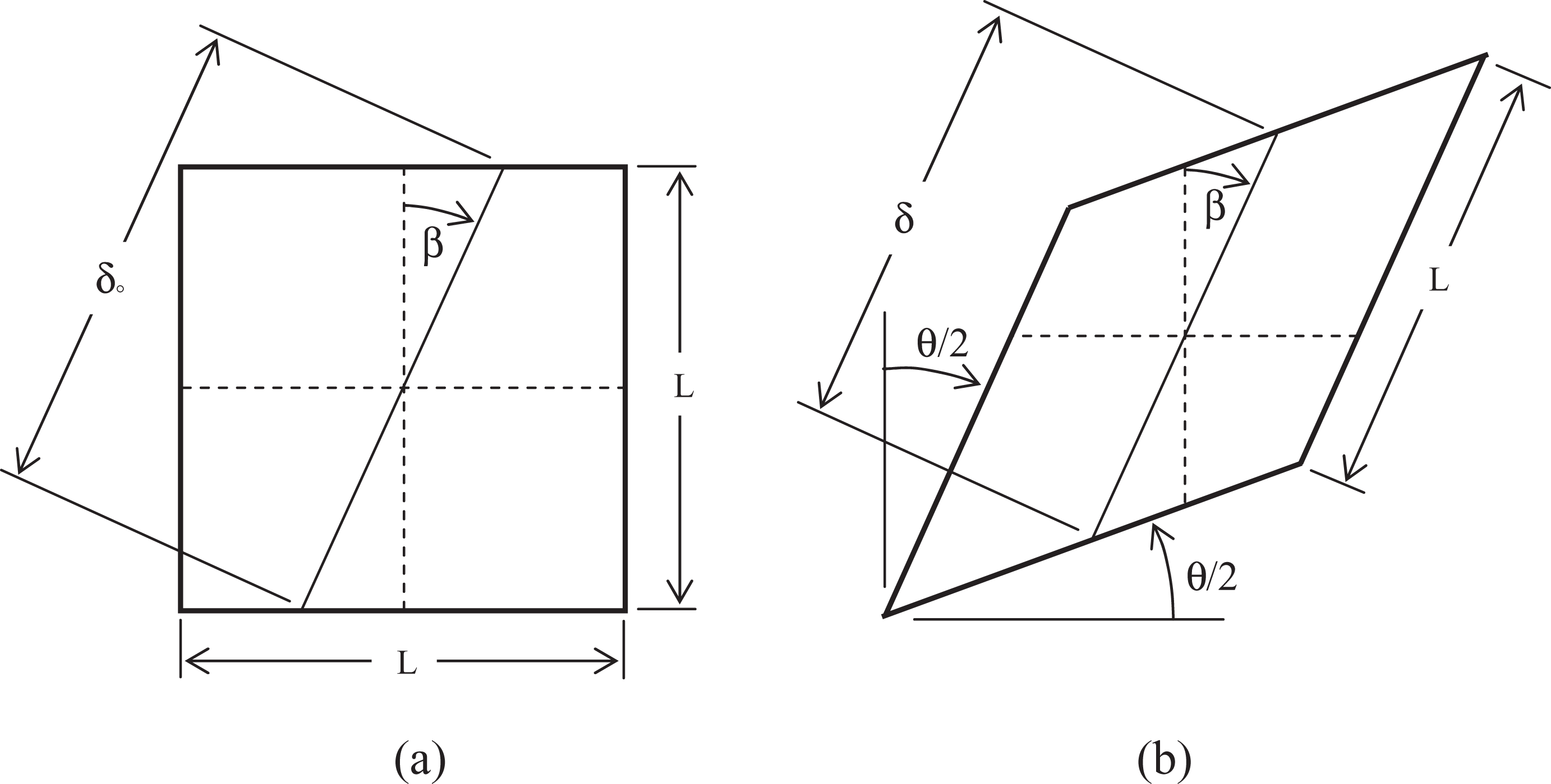

Equation (2) gives the equivalent in-plane normal strain in a direction β relative to the original fiber bundle orientation due to a change in angle θ of the original 90° angle between the woven fiber bundles. Note that β is a fixed angle relative to the mold, assuming no rigid body rotation of the material element, so that it represents a strain in a fixed direction and not a strain in fixed material fiber. These strains, illustrated in Figure 5, are kinematically linked to the original fiber bundle orientation. Figure 5 illustrates the dominance of compressive strain in contrast to sheet metal forming where the tensile normal strains dominate.
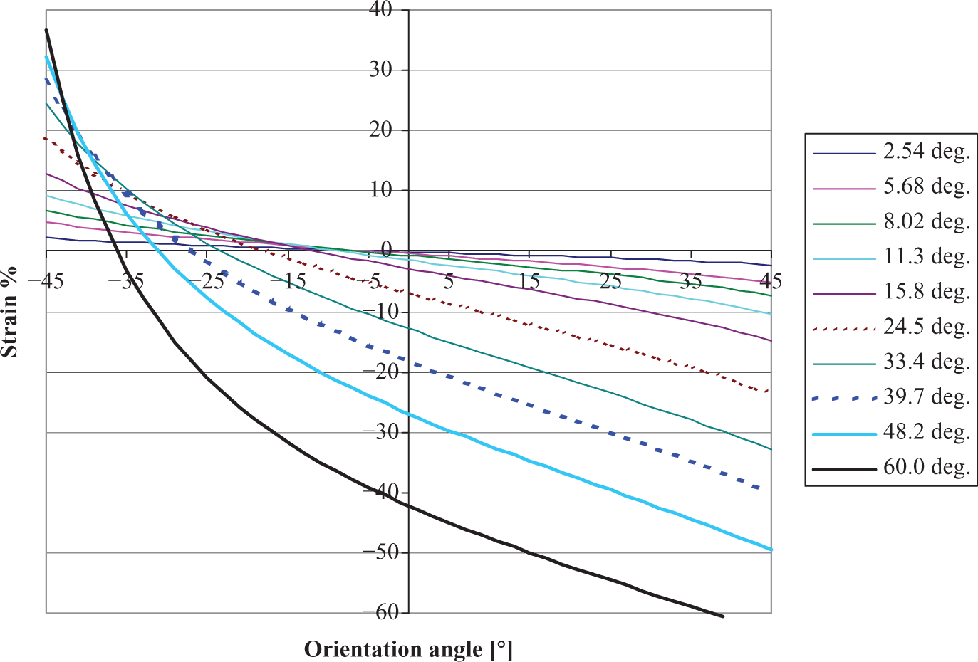
Equivalent in-plane normal strain as a function of orientation relative to original tow axis for various in-plane shear angles.
FE modeling of twill (2/2) fabric shear
To better understand the effective fabric shear properties, the in-plane shear behavior of a 2 × 2 twill fabric was modeled using the concept of a periodic unit cell and the FE method. The overlapping tows were assumed to not translate (slip) relative to one another, but simply rotate on top of each other as though pinned together as illustrated in Figure 3b. For FE modeling purposes, the warp and fill tow cross-sections were assumed to have geometry as defined in Figure 6. The rounded edges helped achieve convergence during edge-to-edge contact. The tapered portion leading to the rounded edge was modeled as a spline curve fit to the three points indicated in Figure 6. The fill tow was 11.136 mm long, while the warp tows were 5.568 mm long. These dimensions resulted in a gap between tows that was 10% of the tow width (5.062 mm).
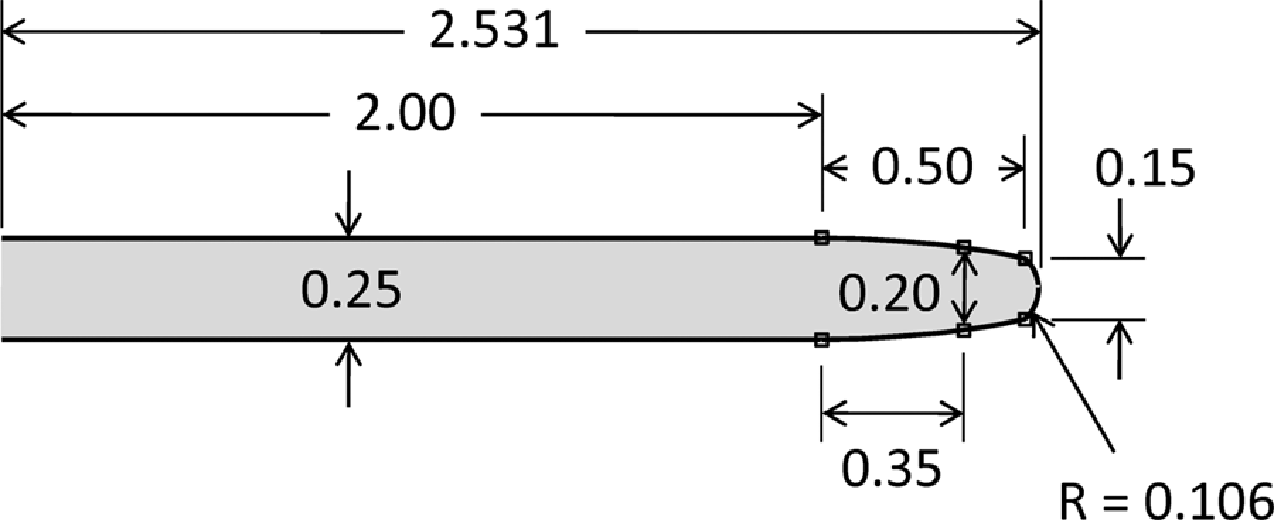
Half cross-section geometry of a tow used in the mesoscale model. Dimensions are in millimeters.
The undeformed geometry and FE mesh are shown in Figure 7. The elements were 8-node trilinear brick elements enhanced with incompatible modes (Abaqus type C3D8I). In the twill weave, the periodic unit cell (Figure 1) can be reduced in volume to that shown in Figure 7 by exploiting rotational/reflective symmetry. 16 The contact between tows is captured using the contact capabilities of the Abaqus FE code. Appropriate boundary conditions must be applied to the nodes on all cut boundaries to properly simulate the assumed periodic fabric deformation behavior. Since these constraints relate nodal degrees of freedom (DOFs) at like locations on different cut boundaries, as well as DOF at symmetric locations on the same face, the node patterns on the cut boundaries must be identical and symmetric about the geometric lines of symmetry on those surfaces. This then facilitates constraint equations that force symmetric (or antisymmetric) deformation of faces. To define these constraints, the following notation was used (see Figure 7).
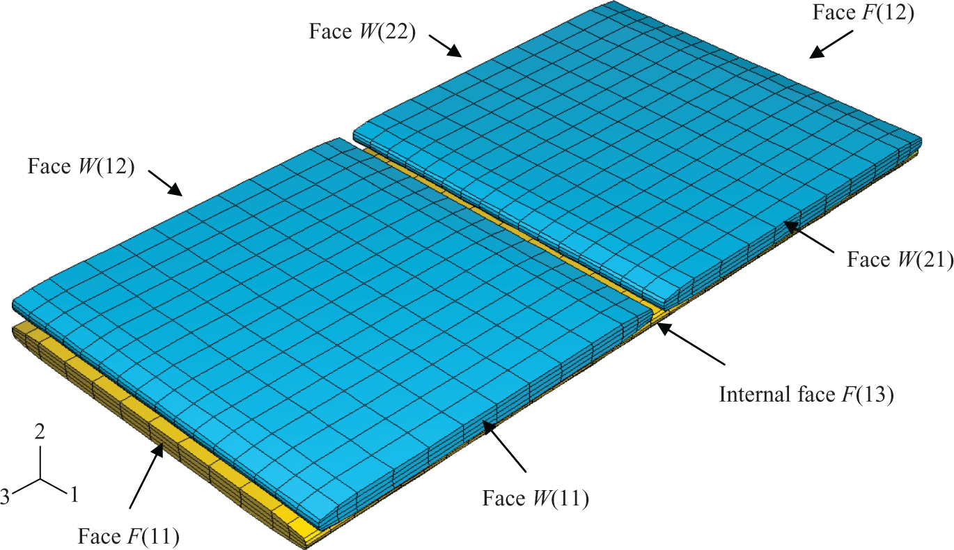
Geometry and finite element (FE) mesh of the twill (2/2) fabric unit cell model.
W 1: warp tow number 1.
W 2: warp tow number 2.
F 1: fill tow.
W( ij): cut boundary (face) j on Wi.
F( ij): cut boundary (face) j on Fi.
F(13): interior surface (3) at mid-span of F 1.
W(ij)c, F(ij)c: face center nodes.
The remaining notation involves sets of nodes whose DOFs are related to each other through kinematic constraint equations. The nodes included in each set are indicated on a sketch of the associated face as shown below. The coordinate frame by each sketch can be related to that shown in Figure 7.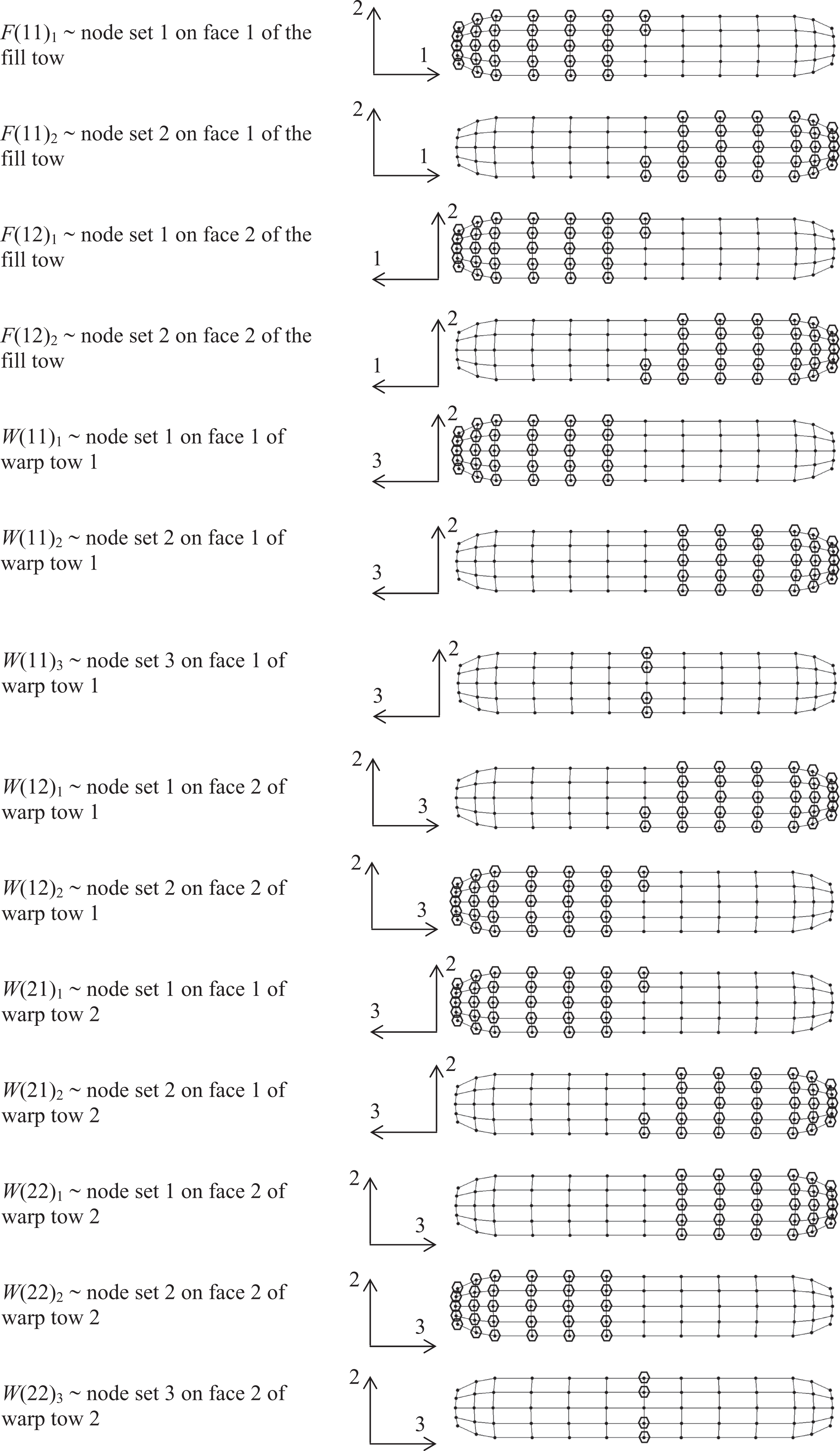
In addition, node sets are defined for an interior ‘face’ that is at mid-length of the fill tow (see Figure 7). It is designated as face number 3 with the following node sets. 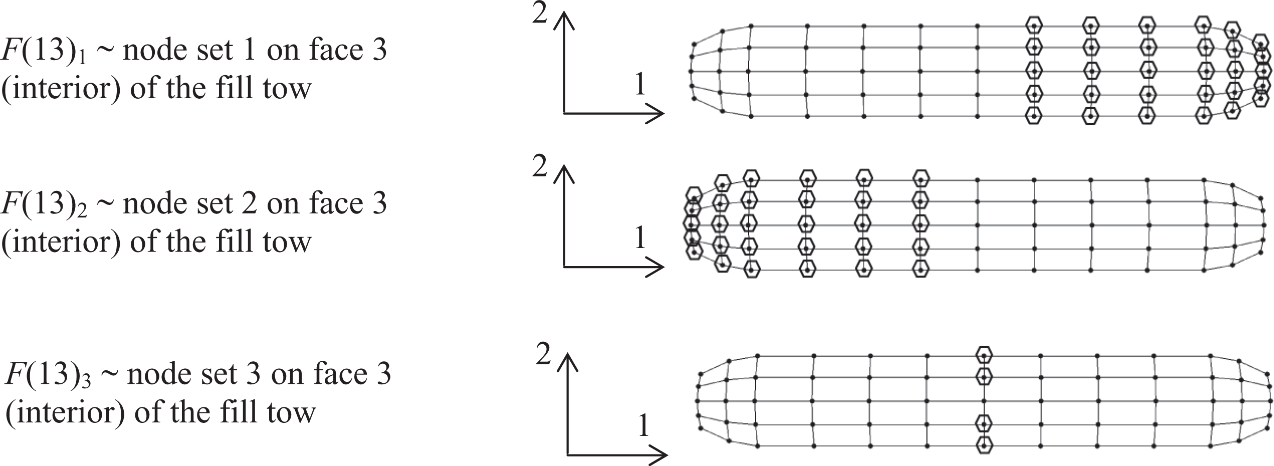
There are three translational DOF per node. The DOFs are designated by a superscript 1, 2, or 3. For example,
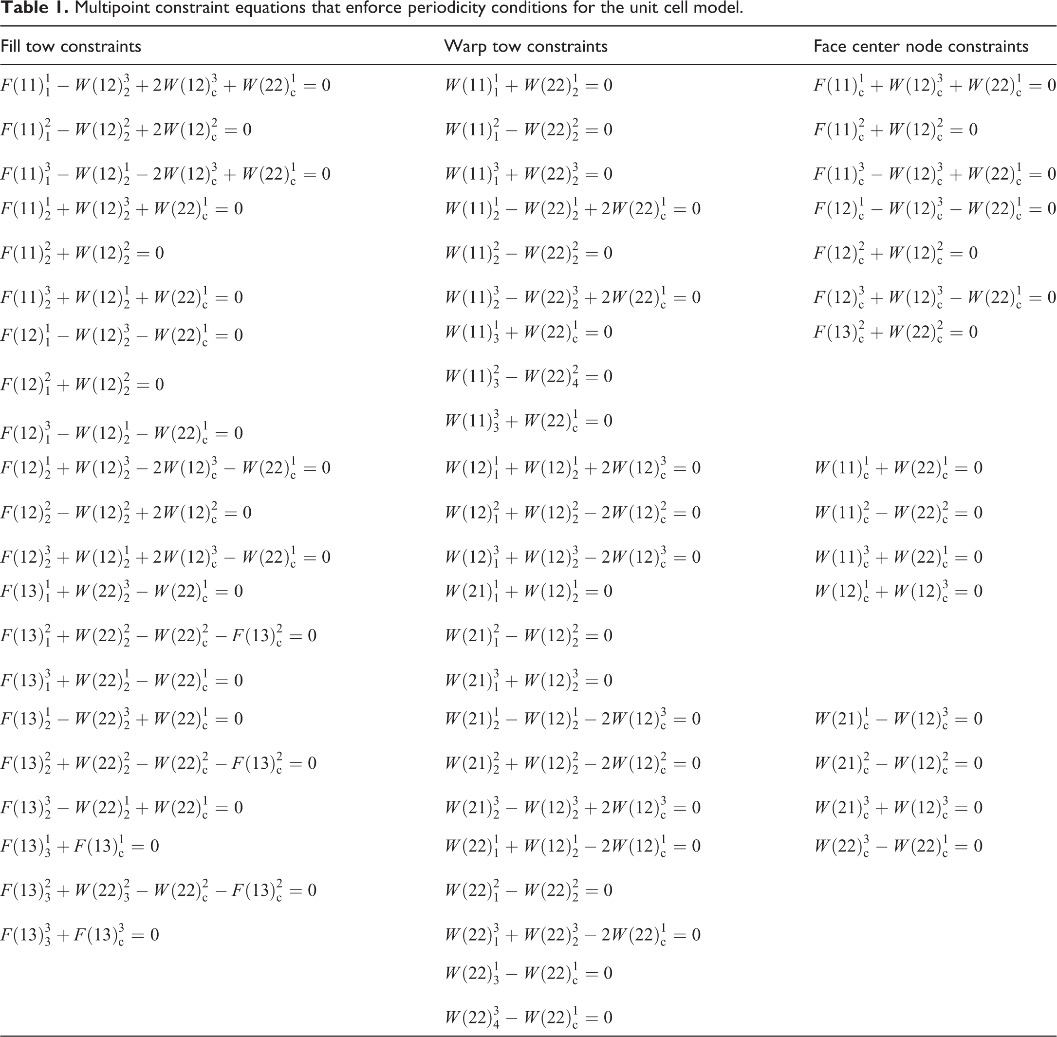
Multipoint constraint equations that enforce periodicity conditions for the unit cell model.
In Figure 8(a), the tow segments are perfectly straight and completely unstressed. With the periodicity constraints in place the woven geometry is accomplished through an FE analysis by displacing the center node on the 2-face of warp tow 1 in the 2-direction until it reaches the mid-thickness of the woven fabric. Figure 8(b) shows the deformed (woven) geometry. This is a unique feature of the present model. Various other models found in the literature generate the woven geometry stress free so there are no initial interaction forces between the contacting tows.
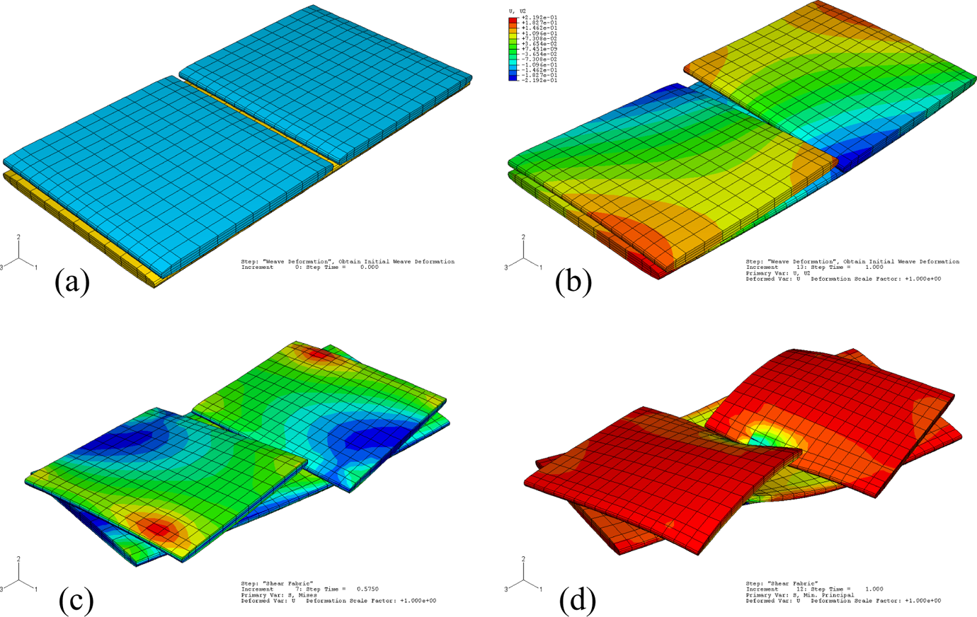
Fabric shear model for twill (2 × 2) weave. Initial model geometry and mesh (a). Model deformed into weave pattern (b). Shear deformation before tow edge contact (c). Deformation after tow edge-to-edge contact (d).
To properly simulate the behavior after the gap closes between the warp tows, additional kinematic constraints are required. The contact surfaces will detect and simulate the edge-to-edge contact of the warp tows, but there are no parallel fill tows included in the model to create the forces of edge-to-edge contact on either side of the single fill tow. For a balanced weave, the edge-to-edge contact and subsequent deformation will be identical to that of the warp tows. Thus, the edges of the fill tow can be kinematically coupled to the impinging edges of the warp tows. The node sets for these constraints are shown below and the images are scaled in the 2-direction by a factor of 8 to separate the nodes for viewing.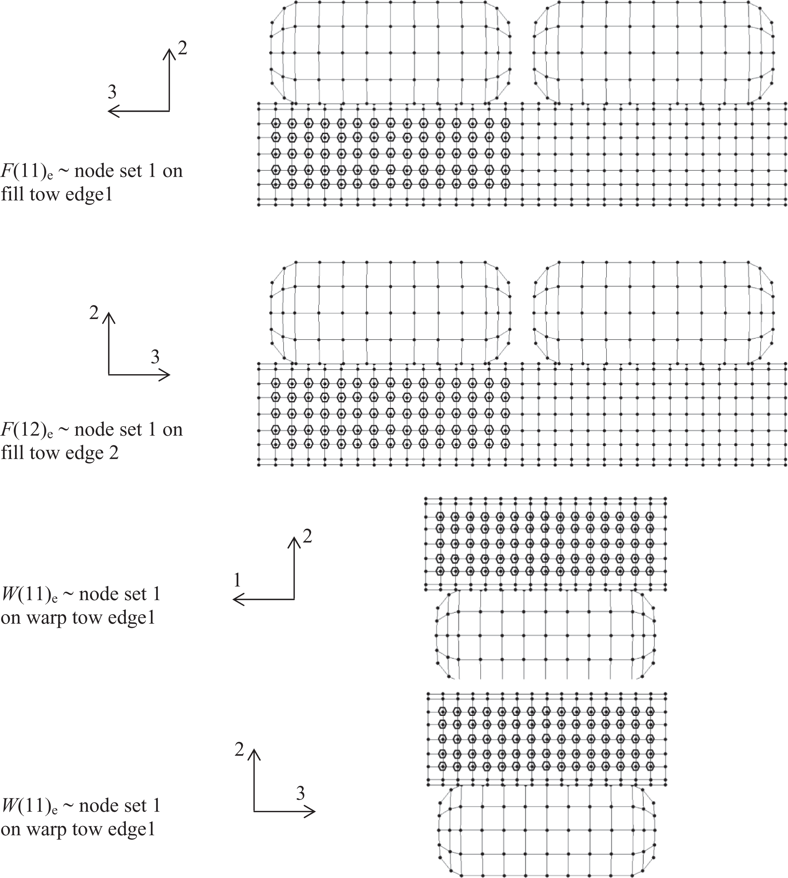
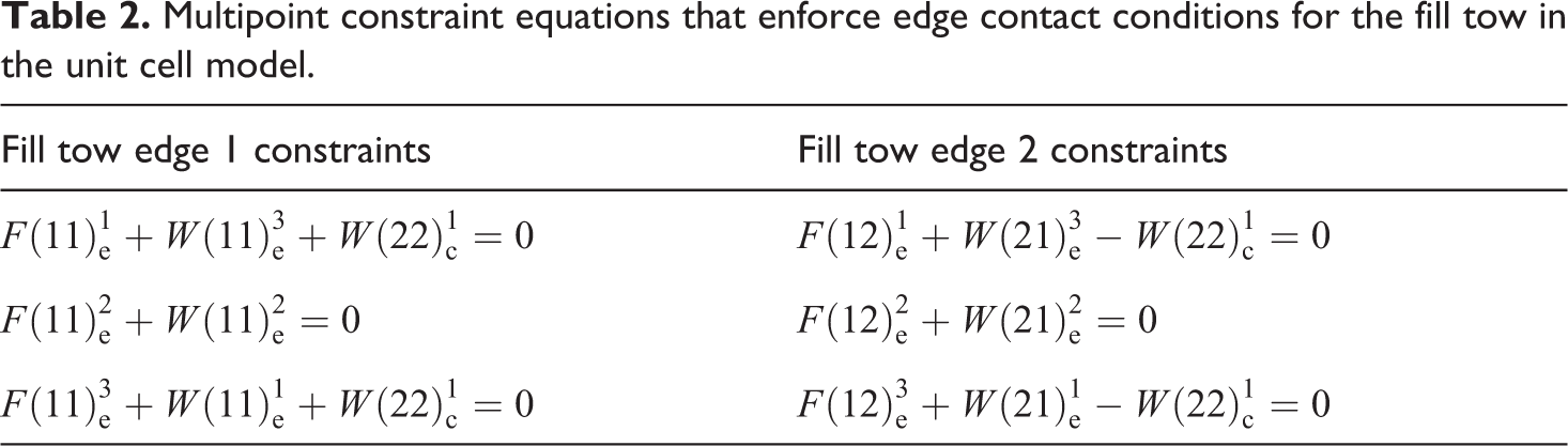
For the warp tows, these node sets are on the edges where the tows contact one another along the rounded outside surface. For the fill tow, the node sets are for the corresponding geometric locations on the edges. The constraint equations implemented between these node sets to simulate the effect of contact along the fill tow edges are listed in Table 2.
Multipoint constraint equations that enforce edge contact conditions for the fill tow in the unit cell model.
The fabric shear model and three deformed configurations of the same are shown in Figure 8. To simulate shear, or relative rotation of the warp and fill tows, DOF 3 of face center node W(12)c was given a prescribed displacement. In Figure 8(c), fabric shear is simulated where the shear angle is less than the initial locking angle. Figure 8(d) shows the deformation resulting from such contact where it is seen that the edge of the fill tow is properly pushed inward as though in contact with an adjacent parallel (ghost) fill tow. The associated shear force was converted into an equivalent shear stress by dividing the effective shear area defined by the rhomboid enclosing the unit cell.
Between contacting tows, the friction coefficient was assumed a constant value of 0.13 as was measured at room temperature. The shear stress due to friction was quite low as shown in Figure 9 but immediately became nonzero because of preexisting stresses due to weaving (crimp) as shown in Figure 8(b). For a normalized gap of 0.10, the model predicts the gap to close at a shear angle between 24.0° and 24.4° compared to 24.6°, given by Eq. (1). The difference is because the FE model was initially generated with gn = 0.10 (Figure 8a), but this gap shrinks slightly when the tows become curved (Figure 8b). After the gap closes, there is a distinct jump in the effective shear stiffness. The overall behavior can be closely approximated as a bilinear function of shear stress versus shear strain as indicated in Figure 9. Note that this result is in contrast to shear stiffness behavior for fabrics of dry fiber bundles where smooth continuous nonlinear material behavior is observed (e.g. Ref 2).
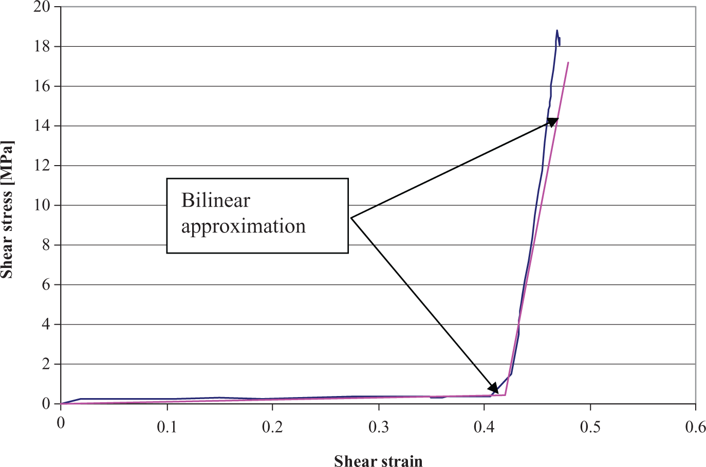
Shear force history showing sharp rise in shear resistance after tow edge contact.
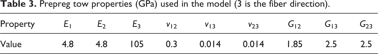
It is important to note that the actual material used in experiments for this project did not have the idealized solid tow represented by the current model. Instead, the prepreg fiber bundles were intentionally resin poor in the center so that they were not completely solid. This gave a more flexible tow for weaving and a fabric with better drape characteristics for forming. Therefore, the subsequent modeling predictions would be expected to be conservative with regard to wrinkle prediction. The material data input to the model for generating the curve shown in Figure 9 are listed in Table 3.
Prepreg tow properties (GPa) used in the model (3 is the fiber direction).
Forming process modelling
Background
A cone-shaped mold shown in Figure 10 was designed and fabricated to conduct forming trials. The forming process involves a stack of unconsolidated fabric layers woven from prepreg and partially consolidated continuous fiber tows. The layers all had the same orientation with fibers aligned initially parallel and perpendicular to the long axis of the mold. The stack (preform) is placed in a heated mold composed of matched metal die surfaces. The mold was closed at low pressure to deform the room temperature preform into the shape of the part and establish contact with the hot mold. After some time allowed for heating at low pressure, elevated pressure was then applied for an additional period of time to fully consolidate the material. Formed parts from the 2 × 2 twill material are shown in Figure 11. It was found that the shape approaches the formability limits of the twill material. The evidence supporting this was that the part could not be successfully formed with the male tool facing upward. This appears to be due to the traction that forms around the flange area of the hot female tool that creates resistance to draw-in and thus modifies the deformation history of the preform as the mold is closed. It was also found that a plain weave material resulted in significant wrinkle. This is believed to be due to the greater in-plane shear resistance offered by the plain weave versus the twill weave.
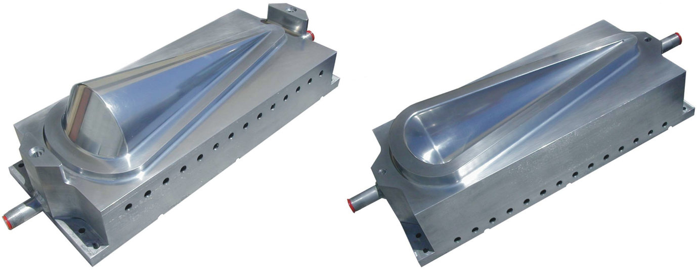
Matched metal dies for molding cone-shaped parts.
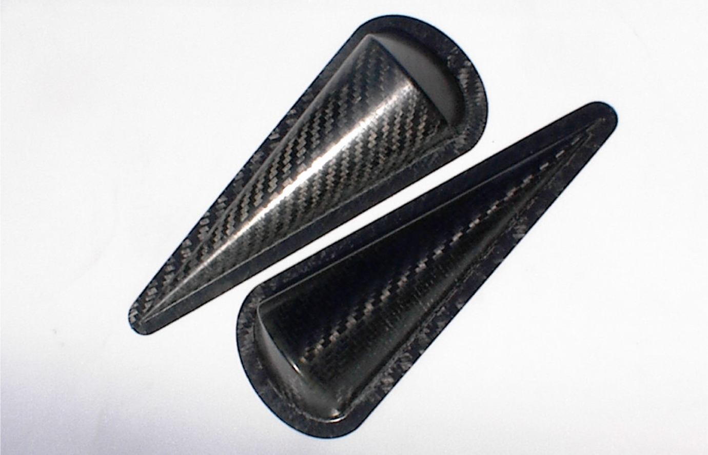
Cone-shaped parts formed from twill (2/2) carbon/nylon 12 k tow fabric.
The explicit version of Abaqus was applied to simulate the forming of the cone-shaped parts. The explicit formulation requires a dynamic analysis but is less computationally expensive than an implicit solution if the velocities are artificially elevated to shorten the simulation time. In this modeling environment, careful consideration must be made of numerical efficiency versus error due to dynamic effects. Initially, parametric studies were conducted assuming linear material properties. In the case of the in-plane shear modulus, a bilinear material behavior was later assumed.
We note here that several authors have devoted considerable effort to developing nonorthogonal constitutive laws to account for fiber bundle rotation due to trellising (e.g. Ref 3). Although differences in in-plane normal behavior are accounted for, no one shows the need for this added complexity by comparing with forming model results for an orthogonal model. Nonorthogonal models are aimed at better characterizing the in-plane normal strains that are independent of trellis shear. These strains are small, on the order of 1%. Typically, strains on the order of 20–40% are needed to form 3D parts. The large effective normal strains associated with trellis shear are specifically directional (Figure 5), but this directionality is accounted for as a geometric effect (rigid rotations) in the nonlinear FE analysis. These observations along with the results found below suggest that nonorthogonal models may be an unnecessary added complexity for this type of formability modeling.
Material properties
For forming simulations, the fiber direction properties are not important because there is relatively little normal strain (∼1%) available for draping the sheet. The main attention is given to trellis shear where significant normal strain (∼20–40%, Figure 5) is available. Initially, linear elastic properties were assigned and the in-plane shear modulus magnitude was varied over several decades to study the effect on formability. For this purpose, a fiber direction elastic modulus of 70 GPa was used in all models and the in-plane shear modulus was varied over 4 decades from 0.5 MPa to 5.0 GPa.
Forming model description
The initial configuration of the model components is shown in Figure 12. The preform is a flat sheet with rounded ends that sit between the cone-shaped die surfaces. The die surfaces simulate a rigid body approximation of the die/preform contact interaction. The truncated conical portion of the die was about 42 cm long. The radius of the cone at the large end was about 7.8 cm with a half cone angle of 10°. The large end of the cone was closed off by cylindrical surfaces whose axes were at an angle of 60° with the cone axis. The larger radius (middle portion) cylinder had a radius of about 11 cm while each edge had a transition to a 3.5-cm radius cylinder. The flange around the perimeter of the model was 2.5 cm wide. Blend radii at intersections of these surfaces where generally about 0.5 cm. The upper die surface and rectangular surface move toward the lower die surface. Because the die surfaces are hot, there was surface melting of the resin and a viscous friction behavior. This will affect the way in which the material is drawn into the die during closure. No attempt was made to characterize this behavior. A Coulomb friction model was assumed with a coefficient of 0.13.
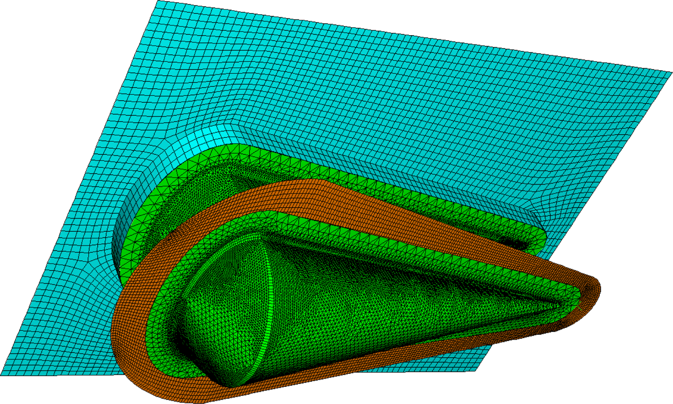
Initial configuration of die surfaces and preform.
The fabric preform was cut, so it extended about 3.8 cm beyond the flange all around to allow for draw-in. The preform was modeled using four-node doubly curved general-purpose shell elements with six DOFs per node, reduced integration, hourglass control, and finite membrane strains. An orthotropic material model was assumed. The quadrilateral shell element neglects out-of-plane normal stress so that only in-plane elastic moduli and Poisson’s ratio are needed along with the three shear moduli of an orthotropic material model. The fiber direction elastic moduli were kept constant at a high value of 70 GPa, reflecting an approximate value for consolidated composite material and the fact that the fiber direction stretching is a negligible contributor to in-plane forming strains. The Poisson’s ratio was also constant at 0.25. The out-of-plane shear moduli were set to the same values as the in-plane value and were varied from 0.5 MPa to 5000 MPa. In these models, as well as the experiments, all plies were assumed to be oriented the same so there was little tendency for inter-ply shear associated with the out-of-plane shear stiffness. The out-of-plane shear moduli were assumed to be of little influence on formability under these conditions.
Modeling results
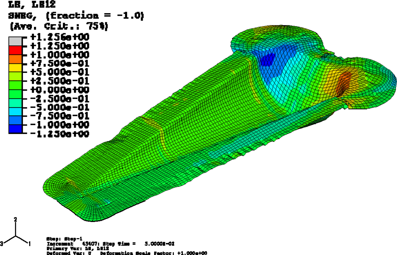
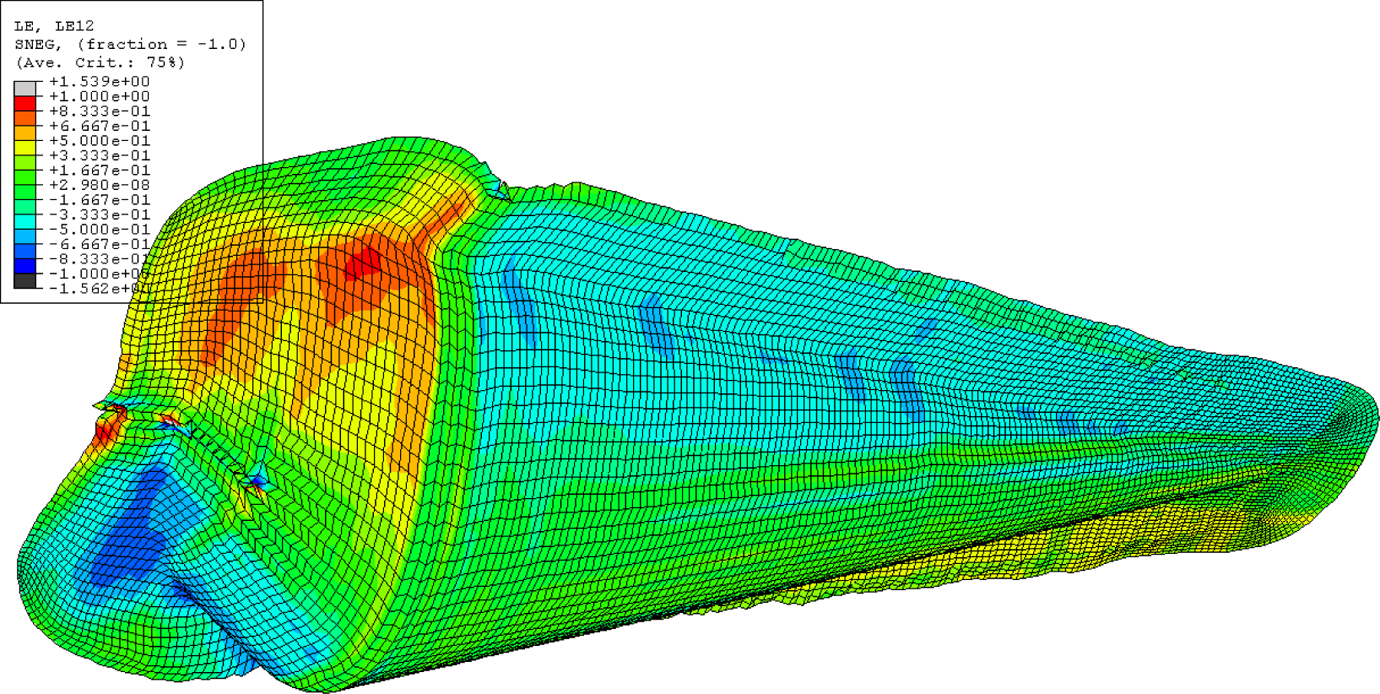
An example of a simulation with the mold partially closed is shown in Figure 13. This figure shows the tendency for wrinkling of the preform around the large end of the cone. In Figure 14 the shape of the fully formed part is shown for the simulation conducted with the largest shear modulus (5 GPa). Superimposed on the deformed mesh are contours of true in-plane shear strain. Relatively little shear strain develops and the fabric is unable to conform to the die shape causing a large fold at the head end of the mold. A one order of magnitude reduction in shear modulus produced a similar result. In Figure 15, the deformed mesh is shown for a simulation in which the shear modulus has been reduced to 50 MPa. As can be seen, the magnitude of shear strain in the head end of the cone has increased considerably and the fold does not develop. It is notable that there is relatively little shear strain in the conical region. This is because the cone is a 2D surface so that no shear is required for a flat sheet to simply bend into a cone. However, both the large end, and to a much lesser extent, the small end impose 3D curvatures and shear stresses are transmitted into the conical portion resulting in some elevated shear strain at the large end of the cone. In Figure 16, the result is shown for further reduction in shear modulus to 0.5 MPa. There are increased levels of shear strain and yet a small fold has formed in the same location but restricted to the flange area. This appeared to be due to the differing interactions with the upper die surfaces. These results indicate that this FE model was able to qualitatively predict a relationship between key material parameters and an important measure of formability (resistance to wrinkle or fold formation).
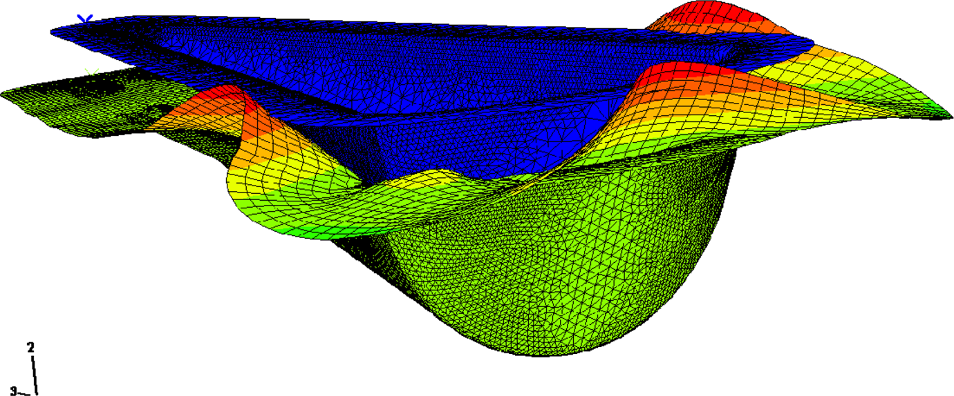
Partially formed part, showing tendency for wrinkle formation around the large end of the cone.
Fully formed part with in-plane shear contours (shear modulus = 5 GPa).
Formed part and in-plane shear contours (shear modulus = 50 MPa).
Formed part and in-plane shear contours (shear modulus = 0.5 MPa).
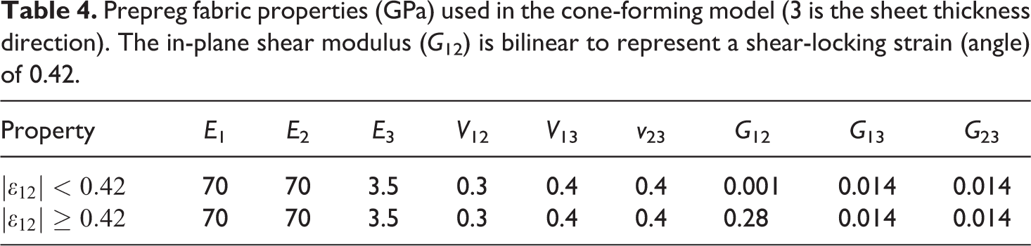
More realistic effective shear properties were obtained from predictions of the mesoscale model (Figure 9). The full set of elastic properties used in this simulation is shown in Table 4. The shear moduli are very low to reflect the fact that only inter-tow friction resists shear deformations. However, the in-plane shear stiffness is elevated at a shear-locking angle of 0.42 radian. This locking angle corresponds to a gap between tows of 10% of the tow width (Figure 3).
Prepreg fabric properties (GPa) used in the cone-forming model (3 is the sheet thickness direction). The in-plane shear modulus (G 12) is bilinear to represent a shear-locking strain (angle) of 0.42.
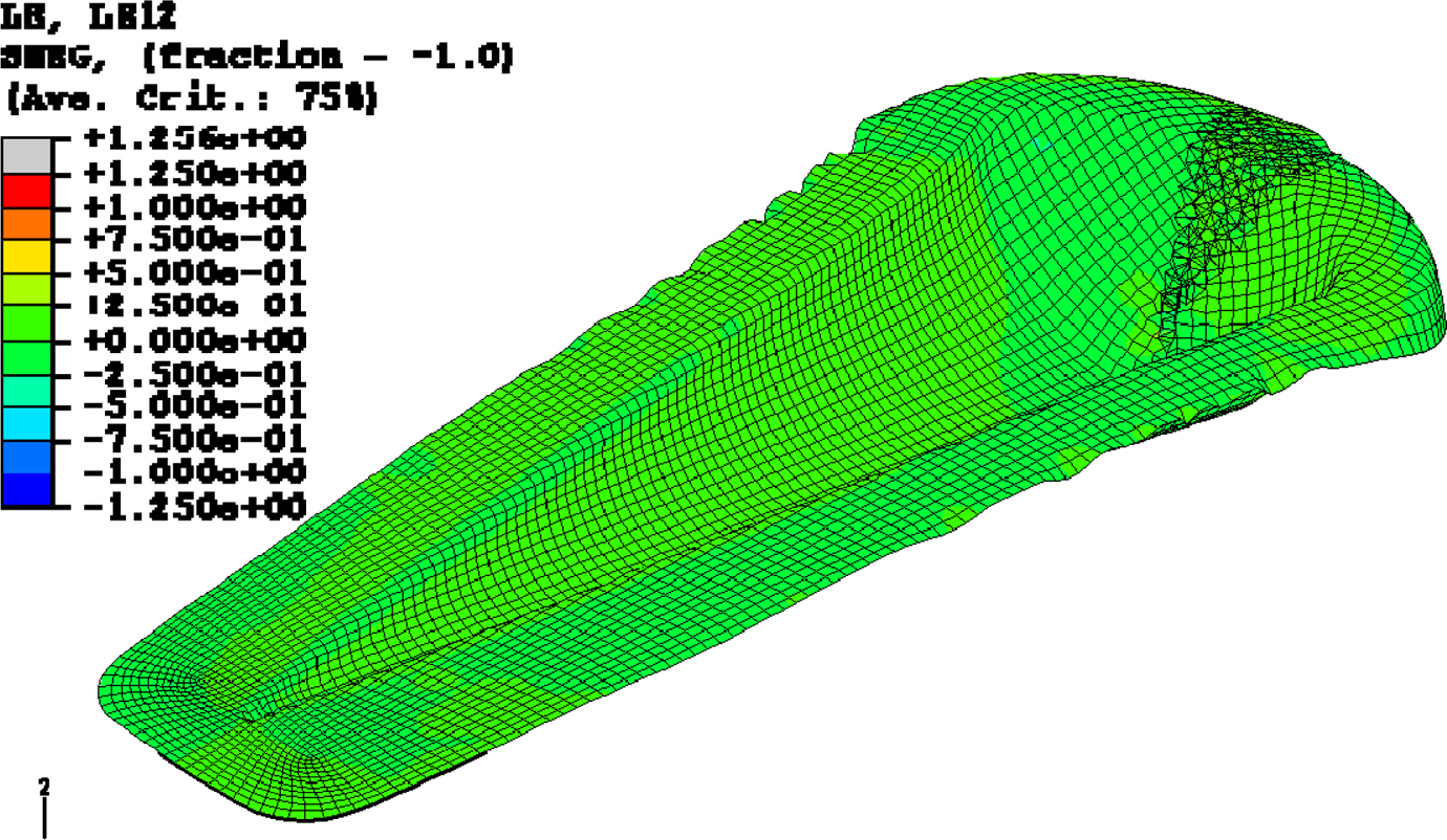
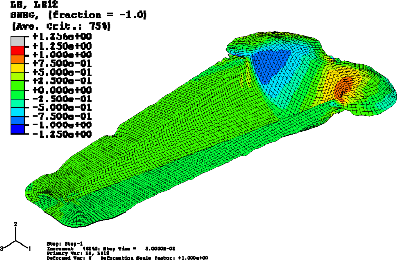
The modeling result is shown in Figure 17. The shear strains have a different distribution but are similar in magnitude to those shown in Figure 15 for a constant in-plane shear modulus of 50 MPa. There is increased shear along the flanks of the conical region. This is explained by observing that the shear-locking angle will be reached in the head end first. When locking occurs, the shear stiffness locally jumps by a factor of 28, and it becomes easier for additional shearing to occur in adjacent areas (e.g., flanks of the cone) that have yet to reach the locking angle. For the linear material models (Figures 15 and 16), there is never any spatial variation of in-plane shear stiffness so the flanks of the cone accumulate less shear strain. Another interesting feature, shown in Figure 17, is the small wrinkle predicted to occur in the same location as the large wrinkles shown in Figure 14. Even more interesting is the comparison shown in Figure 18 with an experimentally observed wrinkle for a forming trial using a plain weave prepreg fabric. It is well known that plain weaves generally are less formable than other weave patterns because they have maximum tow crossover points, which bind and provide resistance to large shear angles. 2 Hence it is no surprise that it is less formable. This actually correlates well with the model predictions since the input properties for the 2 × 2 twill material were suspected to be too stiff due to the fact that the mesoscale fabric shear model did not account for the nonsolid nature of the tows. Hence, it could be expected that use of a softer tow material model might result in no wrinkle formation in the simulation in agreement with the experimental result (Figure 11).
Formed part and in-plane shear contours for a material with a bilinear shear stress–strain behavior based on the fabric unit cell model results.
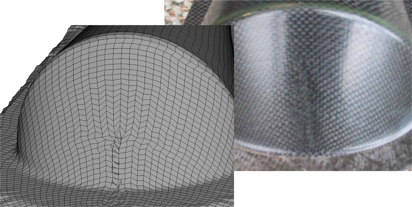
Predicted wrinkle for a twill (2/2) fabric compared to an experimentally observed wrinkle occurring in a plain weave material.
Conclusion
A methodology for modeling matched die molding of thermoplastic woven composite sheet materials was described. Microscale FE models were used to estimate room temperature thermoplastic prepreg tow properties for use in a mesoscale FE model of a fabric periodic unit cell. Results of the mesoscale model yielded in-plane shear properties for macroscale forming process FE model. The model proved capable of predicting qualitative features of formed parts including the location of a wrinkle at the head end of a cone-shaped part. The results also indicate a reasonable quantitative correlation between in-plane shear properties and the appearance of the wrinkle in the simulations. Finally, it is suggested that since fiber direction strains are small (∼1%) compared to effective normal strains due to trellis shear (20–40%) that excessive effort in characterizing stiffness in those directions, including nonorthogonal material models, may be unwarranted. An expression was given for the effective normal strain due to trellis shear in an arbitrary direction relative to the initial fiber direction.
Footnotes
Funding
This work was supported by the U.S. Department of Energy [Contract DE-AC06-76RL01830].