
Abstract
Oil and gas operators have been looking for a more reliable and cost-effective material for their pipelines to substitute steel in pipes and connectors. Reinforced thermoplastic pipes are a popular choice for this purpose, but they are still mainly using steel connectors, which have limited lifetimes due to corrosion. For this reason, efforts are being made to design a non-metallic electrofusion coupler to connect these. This article looks at the current state of the art in electrofusion welding of standard polyethylene pipes and aims to find possibilities of applying this technology to reinforced thermoplastic pipes.
Introduction
In the last 50 years, metallic pipelines have been substituted in many applications by thermoplastic systems. This is due to their significant advantages in environmental resistance, especially their corrosion immunity, little maintenance demands and ease of installation; they can even endure earthquakes. 1 Most newly installed water, sewage and gas distribution pipelines in the United Kingdom are made from polyethylene (PE). The last two decades have seen a rising interest in thermoplastic piping and also a requirement to make them stronger. Reinforced thermoplastic pipes (RTPs) are the result – these are composites of PE, PP, PEEK, PVDF or any other thermoplastic material acting as a matrix, with steel, carbon, glass or aramid fibre as reinforcement. This paper will focus on glass reinforced PE pipes as these are the most common type of RTP and their technology is the most advanced.
There are a number of pipe types for both offshore and onshore systems and they all have their own operating windows and specifications. If they carry crude oil, they are subjected to chemically aggressive, corrosive substances, but also elevated temperatures and high pressures. They need to be leaktight over extremely long lengths, tens and hundreds of kilometres. All these demands are difficult and costly to be met by steel because of it rusting in contact with salt water as well as oil itself, the necessity of cutting the pipe into short segments owing to transport limitations, and the resulting need to make bolted joints between each pipe length.
This review looks at the production and performance of RTPs and the idea of producing an electrofusion joint between them. RTPs are a perfect solution for this purpose because they can be made and transported in long lengths (in spools), and, if connected with electrofusion joints, do not require seals and bolts, have higher resistance to axial loads than steel systems and can potentially have a much longer service life than steel pipes. This offers great savings even considering the higher initial cost of materials of the thermoplastic solution. 2
This article includes a review of conference and journal papers, often produced by pipe manufacturers, on the current state of RTP development as well as requirements given to them. Then follows a description of electrofusion welding and how to assess the strength of an EF joint.
Polyethylene pipes: Standard and reinforced
Standard PE pipes
Polyethylene is one of the most common plastics available, a polymerised unit of ethylene gas – C2H4. It is now an extremely common material when it comes to installing pipelines for multiple uses – water, sewage, gas.
PE pipes come in standardised dimensions as specified in ISO 4427-2
3
and can range from 16 mm to 3m outside diameter. ISO 4065
4
defines the standard thicknesses of the pipes, with the key value being the standard dimension ratio (SDR), which is the approximate ratio of the nominal outside diameter (d
n
) to the nominal wall thickness (e
n
), as in the equation below
5
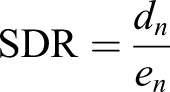
The SDR is valid for all standard pipe diameters, and the higher the SDR, the thinner the pipe is. The SDR can be related to the hoop stress (σh) in thin-walled pipes for internal pipe pressure P using the formula
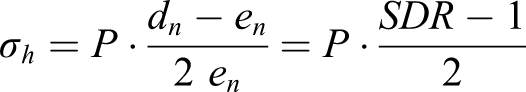
Another important value is the minimum required strength (MRS) – an indicator of the pipe’s ability to withstand hoop stress at 20°C for 50 years, calculated using regression analysis on data from long-term pressure testing. The most widely adopted grades of pipe PE are PE80 and PE100, in which the numbers correspond to MRSs of 8 and 10 MPa.
The above information can then be used to relate SDR to the design hoop stress of PE, which is MRS divided by the overall service coefficient C (or, in other words, the safety factor)
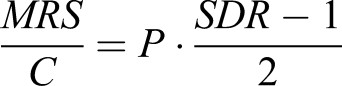
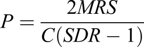
This value of P is called the maximum operating pressure (MOP) and is the pressure rating of the pipe. It is usually expressed in bar, while MRS – in MPa; in this case the following equation is used
PE pipes are made by extrusion. First, the plastic pellets are placed in a screw extruder that stirs the material, which gets hotter and hotter because of the friction-generated heat and external heating. After travelling through the complete length of the extruder barrel, the polymer is completely molten. At a temperature of 200–230°C and a pressure of 14–28 MPa it goes through sizing dies, that give it the designed shape. Finally, pipes, still hot and soft, are cooled with water quickly so that they retain their shape.
Generally, the precise material formulations for commercially available PE are not publicly known, but generally consist of
6
: • carbon black 2–3% – for UV protection, or as colourant, • antioxidants 0.2% – to prevent degradation during processing and oxidation in later life, • stearates – lubricant for extrusion process, acid scavenger, • catalyst residues (TiCl4, MgCl2), mono- and oligomers – production process leftovers • colourants – pipes for different uses may have different colours.
RTPs
Standard PE pipes offer limited mechanical properties. In order to increase the operating pressures reinforced pipes were developed. An RTP is a composite tube where a thermoplastic material is the dominant resin to serve as the matrix for a fibre reinforcement. In recent years RTPs have been starting to replace metal pipelines in the oil and gas sector mainly due to their superior corrosion and weather resistance, lower complete lifecycle cost, 2 damage tolerance and flexibility. RTPs are also better than standard thermoplastic pipes in keeping round profile, ovality is less of a problem due to better stiffness provided by the reinforcement layer; however, it might be aggravated due to spooling.
In this review only PE resin is considered, but other materials (PVC, PP, PPS, PEEK 7 ) are also possible.
Reinforced thermoplastic pipes can be stored and transported in spools, which facilitates the installation in both marine and onshore environments. The diameter of a spool an RTP can be wound on is inversely proportional to the pipe’s tension capacity. As an example, one of the pipes available on the market with the internal diameter of ∼19 cm can have a minimum bending diameter of 5 m and is kept on a spool of 6 m in diameter. 8
The basic components of an RTP are (see Figure 1): • a thermoplastic liner to contain the transported fluid and prevent it from reaching the reinforcement layer; it also acts as the mandrel on which fibres are wound during manufacturing, • a reinforcement layer, windings of fibres to give the pipe strength and resist internal pressure, • an outer cover (‘jacket’) to protect the fibres from the environment. A cross-section through a Reinforced thermoplastic pipe.
The fibre material is usually glass, aramid or carbon. Depending on the fibre layout, RTPs can be: • unbonded (‘dry fibre’) – the fibres are not laminated, but loose, and can move freely within their layer – the cheapest, but quite a rare solution, pipes made this way are the most flexible of all three types, • semi-bonded – the fibres are organised into tapes, so laminated in groups, but the tapes are not fixed to each other, • fully bonded – these are also called thermoplastic composite pipes (TCPs) – all fibres are embedded in the matrix – the most expensive solution, offering the best performance, the stiffest of the three, so the most difficult to spool.
In TCPs, the reinforced layer is effectively unified with the other two layers and any problems related to dislocating fibres or fibre tapes disappear, there is no friction between composite layers, thus the mechanical behaviour is more predictable. 9
Production process of RTPs 10
a) the liner is extruded and rolled on a reel, b) fibres are impregnated in a thermoplastic matrix to create tapes (for semi- and fully bonded), c) the fibres or tapes are wound on the liner and (for TCP) the matrix is welded with the liner using infrared heaters; d) the outer jacket is extruded around the pipe.
Winding angle and mechanical properties
The fibres themselves can be in the form of single filaments, yarns or braids. Also, different angles and winding styles can be used for the reinforcing layer.
11
Winding angle (WA) can range from close to 0° (parallel to the axis of the tube) to almost 90° (parallel to the circumference of the tube), see Figure 2; the angles cannot be equal to 0° and 90° because then there would be no continuity in the reinforced layer. A graphic representation of fibre winding angle options on a pipe.
The WA affects the stiffness and strength of the pipe as well as dominant failure modes (e.g. in internal pressure condition) and the designed angle is always a compromise between good hoop strength, good axial strength and desired bending radius.
The influence of winding angle on failure mode in pure hoop stress is examined in a paper by Kaynak et al.
12
for the case of glass fibre reinforced epoxy pipe: • ∼90° – fibre-matrix debonding followed by fibre fracture – the fibres take all load, • ±65° – as above, plus delamination stage, significant damage to the outer layer, • ±45° – fibre-matrix debonding dominates, • ±25° – little fibre breakage, mostly matrix cracking, • ∼0° – very few to no fibres broken, as the matrix takes all the load.
It is then apparent that at ∼90°WA the hoop strength will be greatest, and axial strength smallest (equal to matrix strength), and the opposite happens at ∼0°; intermediate WA gives intermediate properties.
The failure modes in bending, according to Kremers, 7 work to a similar principle – for 0–22°WA pipes fibre failure is dominant, above 47° the matrix failure dominates, and in the intermediate region (22–47°) a combination of both happens. The minimum bending radius varies with the WA, but the data presented by Kremers 7 suggest the relation is different for each fibre type. In practice, composite pipes most often employ the 55° WA for its optimal mechanical properties.13,14
Connectors for RTPs
In most cases RTPs still use metallic connectors. It is typical of these to clamp both the outside and the inside of the pipe to ensure that transported fluids do not enter the reinforced layer; however, this means reducing the pipe internal diameter, which results in pressure losses and more power required to push the flow. Because of the equipment necessary for the installation of connectors on to the pipe ends, the connectors are normally attached before shipping and the pipes are joined during installation. Steel connectors can also corrode, both on the outside and inside, and their performance relies on the quality of several elements within the joint, including seals, bolts and gaskets, which are made from different materials by different producers.
Thermoplastic connectors are currently being developed as an answer to the above problems. The company Soluforce have built an electrofusion coupler to connect RTPs at pressures up to 125 bar; however, no detailed information is provided.
Gas permeation
Various chemicals that comprise crude oil can readily permeate through PE and can be absorbed faster than by steel. An example is H2S. 15 For this reason, steel connectors have vent holes 16 that allow the gases that have permeated through the inner liner and got trapped in the composite layer of an unbonded RTP to escape safely without risking a pressure build-up in the annulus. Such precautions should not be necessary in the case of TCP, in which there is no annulus, or an empty space for the gas to accumulate, and where no axial transfer of permeated gas is likely, as it only flows in the radial direction, to the outside of the pipe. However, absorption of crude oil ingredients does degrade the mechanical properties of PE and make it swell; therefore, TCP pipelines still require monitoring of the concentration of the permeating substances and sometimes servicing by, for example, flushing the lines with nitrogen. 15
Electrofusion welding
Basic description
Electrofusion is one of methods for joining thermoplastic (predominantly PE) pipes. The process involves preparing two pipe ends by wiping them clean, then scraping them, inserting them into a prefabricated, consumable fitting that includes a heating coil inside. The pipes are then clamped securely in a specially designed fixture. Next, a voltage produced by a generator and computer, commonly called the ‘control unit’, is applied to the coil for a specific time, melting the plastic on the inside of the socket as well as the outer surfaces of the pipes. Finally, the heated area is left to cool down and solidify, creating a strong and stable weld. The fitting becomes an integral part of the pipeline and is therefore designed to have the same pressure rating (MOP) as the pipe. Electrofusion joints are known for their reliability and maintenance-free operation for years.
A schematic of an electrofusion joint is shown in Figure 3. The fitting is usually made by injection moulding. In most cases, it consists of two connected resistance heating coils made of copper or other conductive metal. The coils, which lie within fusion (hot) zones, are surrounded by cold zones. The task of the former is to melt the material and create a weld between the pipe and fitting, and of the latter – to prevent melt from flowing out of the fusion zone, and thus generate the melt pressure needed to produce a weld; moreover, melt flowing outside the fusion zone could cause a threat to operators or contaminate the inside of the pipes, or generate a stress concentration that could initiate a crack. The heating element consists of two sets of coils connected to each other, which start and end with an electric terminal, where cables from the control units are attached. There normally is a protrusion in the middle of the fitting (centre stop) that prevents the operator from sliding the pipes too deep inside the fitting. The two small indicator pins sticking out at the bottom are pushed out by the melt pressure, proving that melt has been generated. A cross-section through an electrofusion joint.
Pipe preparation
Pipes to be welded in an EF socket should be cut at right angles and the end surfaces should be free of swarf, which may pose an obstruction when the pipe is inserted in the fitting.
One of the most important factors influencing the joint quality is the cleanliness of the outside pipe surface prior to it being inserted into the fitting. Contamination may result in defects (see section Fusion interface contamination). To keep them free from dirt, EF fittings are supplied in sealed bags to be opened just before use. Pipes, on the other hand, should be dry and cleaned of contaminations like grease or soil. The outer surfaces of the pipes to be welded are scraped off; this is believed to remove an oxide layer created by reaction to UV radiation or during the extrusion process. It is also said that care needs to be taken so that welding is performed as quickly as possible after the pipes are scraped. It is standard practice to peel off no less than 0.2 mm of the material carefully and evenly, so that none of the original surface is left. It is best done with a mechanical scraper.
It should not be forgotten that after inserting the pipe ends into the fitting, both pipes should be securely clamped, since pipe misalignment and movement during welding will reduce the joint quality.
Electrofusion welding process parameters
Basics
Three basic parameters for determining a correct welding process are time, temperature and pressure and they have to be coordinated to achieve a satisfactory weld. Also important is the material grade which determines how easily molten plastic can flow between the wires and on to the pipe surface.
The options that allow EF fitting designers to manipulate these parameters include • wire layout – that is, coil length, wire spacing, depth, geometry • wire material and thickness • fitting material grade • cold zones layout • size of the clearance between pipe and coupler surfaces • heating time, also referred to as specified fusion time (SFT).
To raise the temperature of the plastic, voltage is applied to the terminals. It is produced by the control unit for a set amount of time in order to reach the correct pressure and temperature of the melt generated in the fusion zones. A widely adopted practice is to place a label with a bar code on the EF fitting that contains the welding data and can be read by a reader attached to the control unit. This allows for excellent repeatability – there is no need for the operator to input the data, hence fewer opportunities for mistakes.
The melting temperature of PE100 is around 130–135°C, but it has to be exceeded in order to obtain a good weld, as a sufficient amount of both the fitting and pipe material must be melted. Care should be taken; however, that the optimum welding temperature is not exceeded, because if it is too high, the material may degrade, making brittle failure more probable. A minimum melt pressure level also exists, below which fusion does not happen to a sufficient level and the strength of the joint is impaired. 17
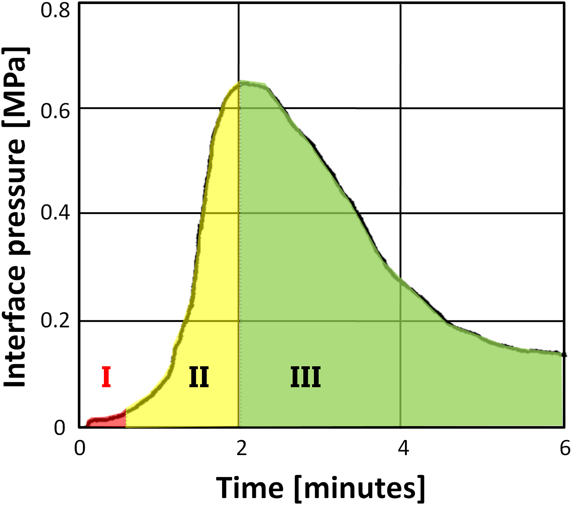
When heated, the polymer first expands in the solid state, then it gradually melts, still expanding. When it reaches the cold zones, it cools down and solidifies, so the pressure in the fusion zones begins to rise, because of further amounts of plastic still melting. Graphs of interfacial pressure as a function of welding time, shown in Figure 4, provide a convenient way of understanding the process. Three basic phases can be identified in these: I. – incubation phase – when no melting is occurring yet, the interface is just starting to get warm and expanding slowly; II. – rise and peak phase – now the polymer starts melting and expanding quickly, filling the voids, and the pressure rises significantly; III. – cooling phase – the current is stopped, the pressure slowly decreases, as the polymer contracts while solidifying. EF welding pressure versus time graph for a 4-inch coupler, with the pressure profile divided into three phases (coloured). Data from Bowman.
18
The further sections provide more details about the influence of various factors on the strength of the joint.
Temperature
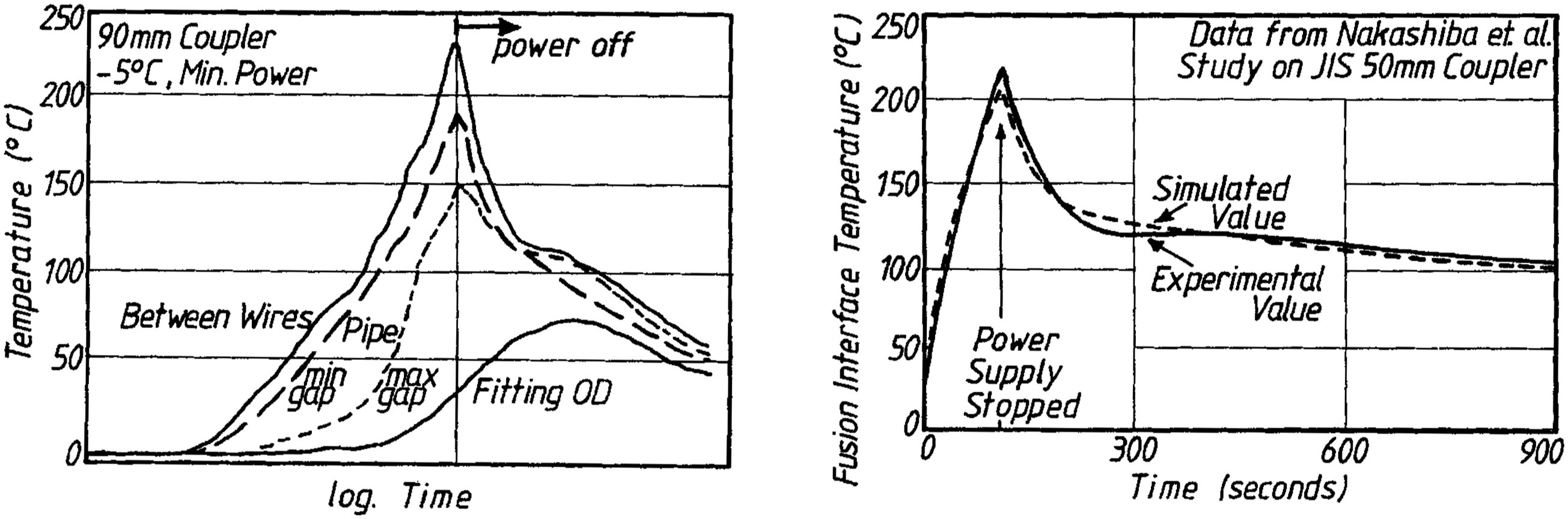
According to simulations by Nakashiba et al.. 19 , the minimum temperature the welding interface has to reach in order for the joint to be safe is 150°C, which is similar to the value of 160°C suggested by Fujikake et al. 20
After the desired temperature is reached, power is cut off and the cooling stage begins. Initially, the interface temperature drops down quickly, but then stabilises at 120°C due to PE crystallisation – see Figure 5. The coupler surface heats slower than the interface, so it becomes hottest sometime after the current is stopped, which is visible on the graph. (a) measured temperature during EF taken at various points; (b) measured and modelled temperature data compared.
18
It is vital not to overheat the joint. According to Shi et al., when the material is degraded by having been heated for more than 140% of SFT, 21 or when the PE surrounding the heating wires reached 350°C 20 , the material is weakened and practically unfunctional.18,21 As claimed by Shi et al., 21 in the 90 mm diameter joints they were testing, between 55% and 140%SFT, the strength was fairly constant. This finding agrees with the ‘plateau region’ phenomenon described by Bowman 18 – the strength increasing quickly during the rise and peak phase as shown in Figure 4 until ∼80% SFT was reached and then staying fairly constant until 140% SFT. The precise values may differ depending on the size of the coupler.
According to Fujikake et al., 20 the temperature of the inner pipe wall should not exceed 110°C, otherwise the stiffness of the pipe is impaired.
Appropriate cooling is of importance to the quality of the weld; joints should be cooled while the pipes are still clamped, free from any loads. ISO 12176-2 22 specifies allowable ambient temperatures for EF welding from −10°C to +40°C. When working in the field, it is thus necessary to set heaters nearby if it is too cold or tents to provide shade that prevents the sun from heating the pipeline; in hot weather cooling takes longer. Sudden quenching results in internal stresses generation in the joint, possibly compromising its quality.
The adverse effect of extreme ambient temperatures can be partly compensated for by adjusting the heating energy. The rule suggested by Usclat 23 was to subtract or add 0.7% of the original energy value per 1°C more or less. Usually, it is easiest achieved by changing the heating time – modern control units have a function to adjust this automatically depending on the ambient conditions.
Gap size and melt pressure
One of the most important aspects of EF fittings design is the gap size – the gap (or clearance) in question being the space between the fitting bore and the pipe outer surface – because it influences the time required to reach the optimal melt pressure. Two approaches to this problem are employed in industry: tight fit and loose fit. In the former, the bore of the fitting is manufactured to be a minimum distance away from the pipe, so that little expansion is required to create a joint. Higher pressures in the same amount of time are achieved in this case and the incubation period is shorter, and, according to Usclat, 23 higher absolute values of pressure can be reached. Nussbaum et al. 24 also claimed that a higher temperature is reached with tighter clearance for the same welding energy. The disadvantage of tight clearance strategy is that only pipes of perfect roundness can be used. Increasing the gap allows for a more tolerant approach. On the other hand, longer fusion time and more power is required, which might result in unstable behaviour and defects, and longer cooling is necessary. 23 Hilger et al. 17 found that tighter-fitting joints tended to reach a higher pressure in a fixed time, and performed better in mechanical tests. In strip-bend tests the joints, in which the melt pressure did not reach 1 bar, failed. According to Fujikake et al., 20 the peak interface pressure should be between 0.98 bar and 9.8 bar. It is then important while scraping pipes not to take off too much material.
According to Bowman, 110 mm EF joints with gap sizes up to 2% of the outer diameter of the welded pipe (2.2 mm) seem to be the strongest for a fixed power value. This clearance size is not far from the results obtained by Hilger et al. 17 of 1.6–3 mm (the size of the coupler was not precisely stated in the paper, but it was most likely less than 250 mm in diameter).
However, a different result was obtained by Usclat 23 – a 0.2 mm clearance for a 125 mm coupler was compared with a 0.6 mm gap and the author claimed that in the looser case the welding pressure was not sufficient and the weld was weaker. Usclat suggested this could be explained by the difference between post-welding residual stresses in loose and tight gap joints – the molten plastic on the inside of the fitting expands during heating and touches the pipe, creating a weld; in loose-fit joints it has to fill the space between the two elements. Then, when it is cooled, it shrinks back to its solid-state density. This creates a tensile residual stress in the ‘bridge’ between the two parts, resulting in a weaker weld. In tight-fit joints, the melt has nowhere to go, so the pressure rises, resulting in compressive stresses after solidifying, according to the author.
Riahi et al. 25 attempted to investigate the effect of clearance size and analysed gaps in the range of 0.4–1.5 mm. However, they did not test actual couplers and pipes, but instead used simplistic samples made from two flat PE plates with heating wire attached to one; the plates were spaced away from each other with thin plates of aluminium; such setups were then placed in a fixture with adjustable clamping pressure and connected to an EF control unit. The findings were that the achieved peak interface temperatures rose quickly starting from 0.5 mm clearance, the highest values were reached between 0.6 and 0.8 mm, and then they decreased slowly. To establish the influence on weld performance, the samples were tested with lap shear strength procedure (ASTM D1002). 26 The conclusion the authors reached was that enlarging the gap over an optimum value weakened the weld, but making it too tight could result in too high the pressure that could push the melt out of the fusion zone and, thus, reduced strength. The conclusions of both Usclat and Riahi can be correct depending on the coupler design – if the design is intended to accommodate a large gap and not enough energy is applied, the PE will not fill the clearance completely and no weld will be formed. However, when the coupler is designed for a tight fit, too much power will result in excessive amount of melt and wires dislocation or even melt leaking into the pipe or outside the coupler. This might not have been the case with the paper by Riahi et al., where the samples seem too small and narrow to have a cold zone that would stop the melt from leaking out of the sides at high pressure, hence the weak weld between the plates.
Material
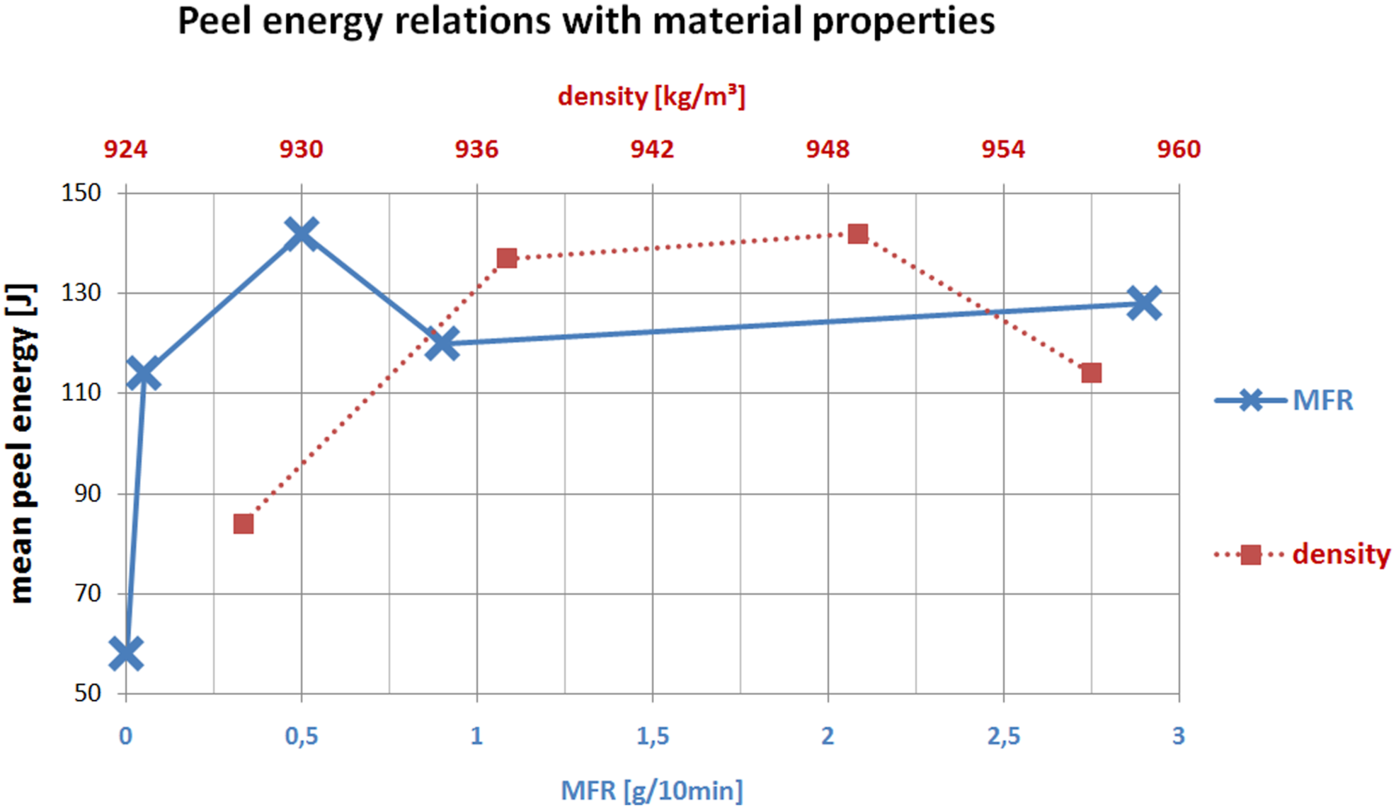
The grade of PE used does matter when investigating EF weld strength. One of the aspects is molecular weight M w . Increasing M w results in decreasing melt flow rate (MFR), which is a measure of how viscous the molten plastic is, how quickly it can move. For PE pipe grades, the value is ≤4 g/10 min and most commonly 0.3–1 g/10 min (at 190°C and 5 kg), but also pipes with an MFR of 0 (cross-linked PE) can be welded, 27 as long as the coupler is made from a grade that can flow. According to Bowman 18 , for MFRs between 0.4 and 3 g/10 min weld strengths do not differ.
Another factor possibly influencing the weld strength is crystallinity, which is proportional to density. Data presented by Bowman
18
showed that a wide range of PE grades can be successfully joined by EF, see Figure 6. Peel energy dependence on material properties. The lower x axis relates to melt flow rate, the upper x axis represents density values. Data from Bowman.
18
Assessing the strength of electrofusion joints – testing methods
Destructive tests
The most common way of testing the strength of an EF joint is to cut longitudinal coupons from it and perform mechanical tests on them, although complete joints can also be tested. Short-term tests provide data quickly for quality control purposes, but it is important to note that the results do not necessarily correlate with how a joint will perform in the long term.
The following sections describe a selection of the most common destructive tests used in industry.
Peel decohesion tests
These types of tests are one of the most common methods of assessing EF joints strength. Variants are standardised under ISO 13954
28
and EN 12814-4.
29
In order to perform this type of test, a parallel-sided coupon is cut from a joint. The two standards use different coupon shapes, as shown in Figure 7. The specimens are pulled apart (for EN – perpendicular to the joint interface, and for ISO – parallel to it) at room temperature and a speed of 25 mm/min until complete separation. The percentage of the surface that breaks in a brittle manner is determined. (a) EN 12814-4 Peel decohesion test configuration; (b) ISO 13954 operates at a similar principle, but the setup is different. (courtesy of TWI Ltd.).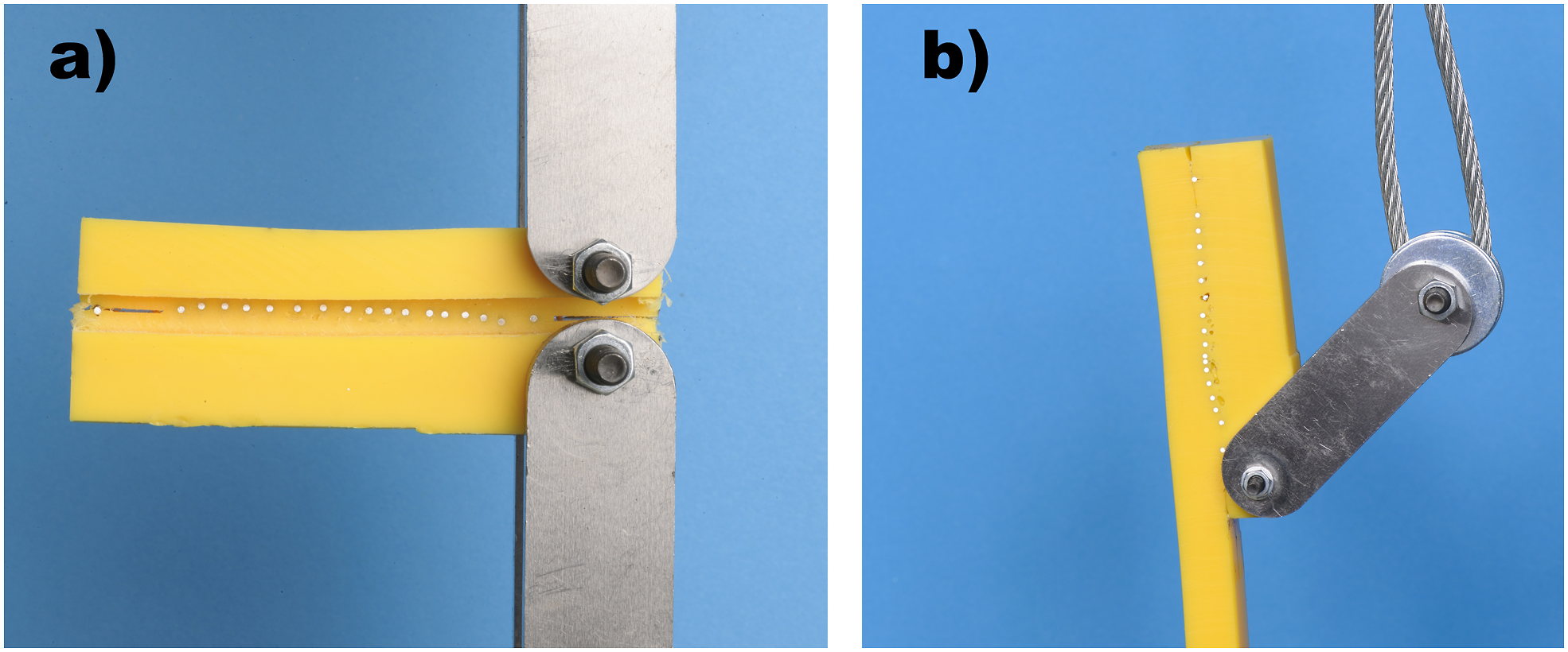
Crush tests
The next family of destructive tests is crush tests, as specified in EN 12814-4, 29 ISO 13955 30 and ASTM F1055. 31 These tests are normally for smaller joints (up to 90 mm), coupons from which would be unsuitable for peel decohesion testing, because their walls are too thin to support the loads created by the loading pins.
In EN12814-4, 29 to perform the test, a welded joint is axially sectioned in half. One end of the pipe is then placed in a vice perpendicular to the sectioning axis just below the end of the fitting and squeezed until the two inner surfaces of the pipe touch. The specimen is held in this position for 10 min. The test is considered passed if the fusion interface cracks only up to the second turn of the heating wire coil; any further crack growth is not acceptable.
In ISO 13955 the procedure is very similar but, once the inner pipe surfaces touch, a lever is used to separate the fitting from the pipe and the percentage of the welded surface that failed in a brittle manner is calculated to establish whether the joint is acceptable.
Strip-bend test
This test is standardised under ISO 21751. 32 A coupon is cut longitudinally from the complete joint and the fitting part of the coupon is clamped in a vice. Then the pipe part is grabbed with pliers by the outer cold zone area and twisted slowly (2–3 s per move) up and down perpendicularly to the coupon’s length. The same is done step by step along the coupon’s axis until the inner cold zone is reached. The position and type of failure is reported and the brittle failure percentage calculated.
Hydrostatic pressure tests
Hydrostatic tests are important as they try to represent the real operating conditions of a joint. They can be either short term or long term.
Generally, pressure tests at 80°C are employed to assess the resistance to slow crack growth, and at 20°C it is the ductile strength of the joint and whether the coupler thickness is sufficient for the given pressure that is determined. 18
A short term burst test is described in Annex D of BS EN 12201-3 33 : a test piece consisting of an EF joint, with the pipes cut short to prevent their failure prior to the failure of the joint, is placed in a water bath at a constant temperature of 20°C; the pressure is increased at a rate of 5 bar/min until the sample fails. The internal pressure is then recorded at burst, together with the time, mode and location of failure.
Long-term tests are listed in ISO 4427-3 3 and 4437-3, 34 and EN 1555-3, 35 EN 12201-3 33 in three variants: 100 h at 20°C, 165 h at 80°C and 1 000 h at 80°C, where the requirement is that the joint does not fail at any point. The joints are submerged in water and filled with water. The testing pressures (for PE100) are 5, 5.4 and 12 MPa, respectively, for 1 000 h, 165 h and 100 h variants.
A similar principle but with slightly different parameters is described in ASTM F1055. 31
Pressure tests at 80°C are used to give fittings their pressure ratings. 36
Coupon tensile creep rupture test
This type of test is normally used for assessing butt fusion joints, but a variant, standardised in Annex D of BS EN 12814-3
37
was developed for EF welds and can be applied to sockets with a minimum wall thickness of 8 mm. To perform it, 25 mm diameter cylindrical specimens are cut from both fusion zones and include the heating wire and fusion interface; they should contain at least three wires and be free from voids. Then the cylinder is butt welded from both sides to extension bars which will be attached to the creep rupture test machine set to 3 N/mm2. The specimen manufacturing procedure is shown in Figure 8 a-d and 8e shows the experimental setup.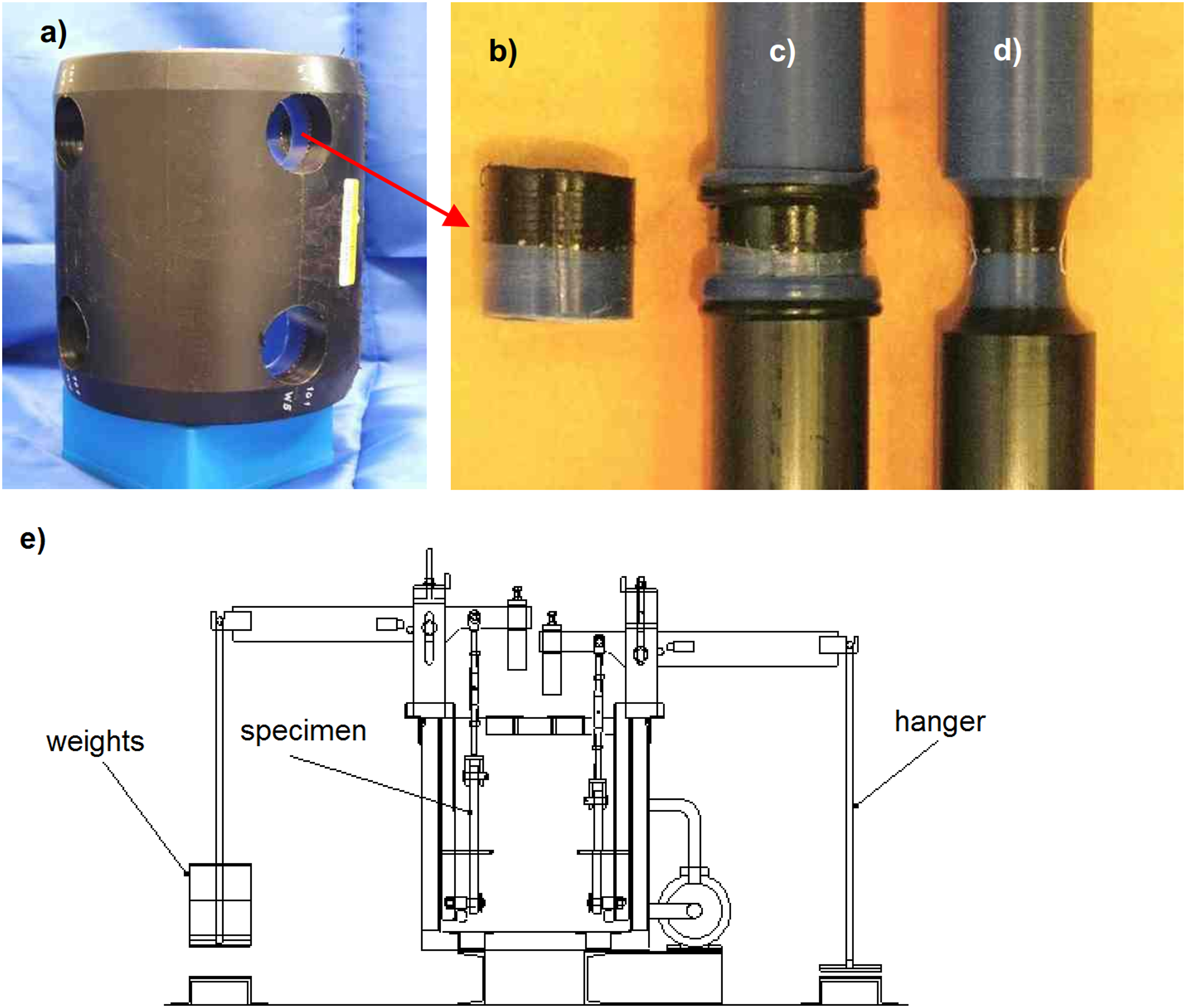
The test is carried out in water (or other fluid) at an elevated temperature (normally 80°C) and the time to rupture is recorded.
Whole pipe tensile creep rupture test
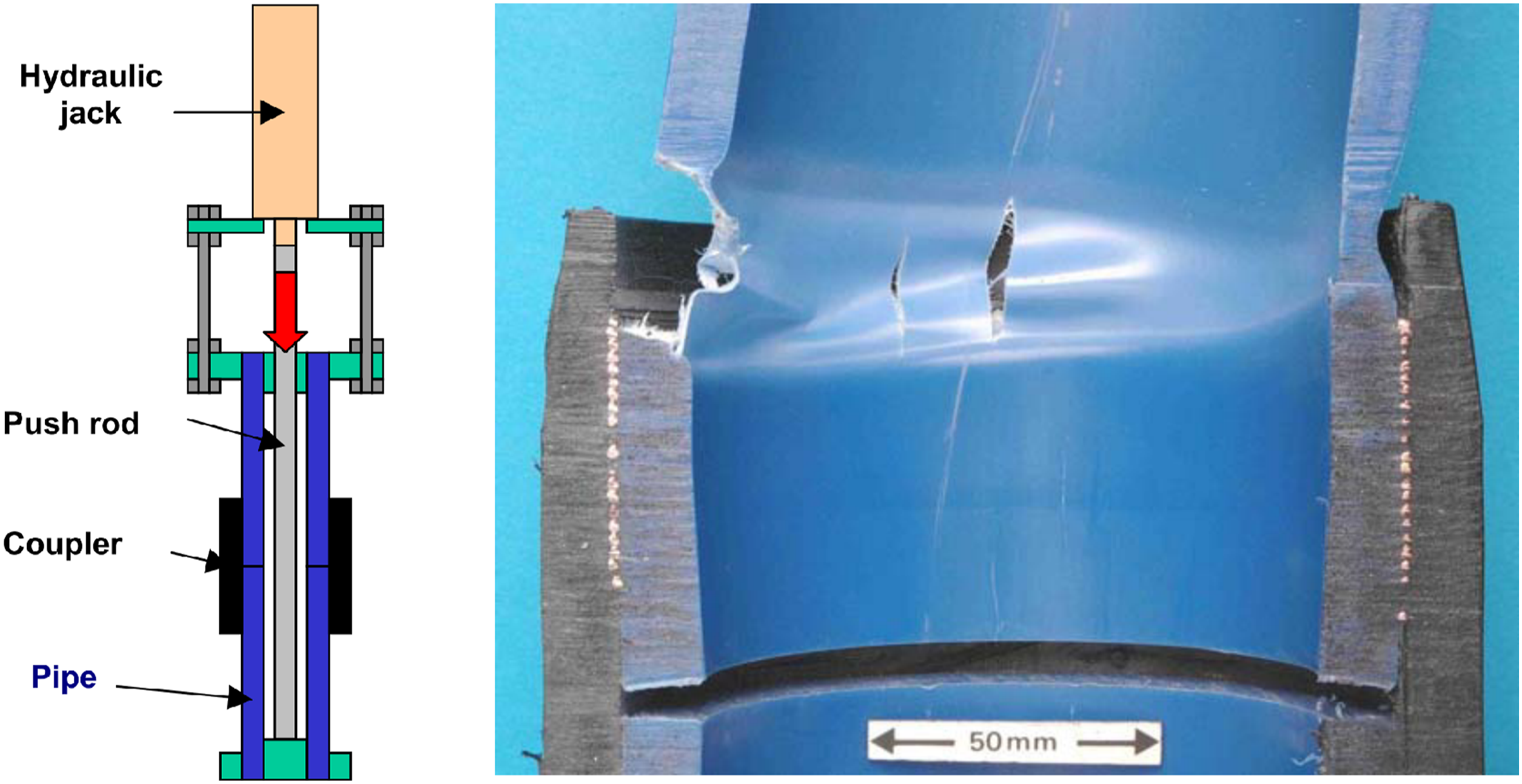
This test is not commonly used in industry, although it is defined in EN 12814-3. 37 To perform it, a complete joint is clamped at the pipe ends, with one clamp being fixed and the other attached to a push rod powered by a hydraulic cylinder; the EF assembly is immersed in water (or any other medium, if necessary) at a temperature of 80°C. The assembly is subjected to a constant load at a set elevated temperature until fracture occurs. The time to failure and the location of failure are recorded.
This test was used by Troughton et al.,
38
where a joint was subjected to a tensile stress of 5.5 MPa while immersed in water at 80°C. As Figure 9 shows, the failure occurred through the pipe wall, initiating from the outer cold zone notch. A schematic of the whole pipe tensile creep rupture test and a photo of a failed sample.
38
Destructive tests – a summary
As Troughton et al. found, results of all destructive tests are not necessarily coherent. Interestingly, short-term tested joints containing fine particulate contamination failed through the fusion interface, but with all other flaws and with unflawed joints the failure was either through the pipe wall or through the plane of the heating wire coil, except for the long-term hydrostatic tests, which always failed through the fitting body, regardless of any of the above flaws present in the weld. Coupon tensile creep rupture test could in a number of cases discriminate between unflawed or fine particulate contaminated joints and cold welds. 38
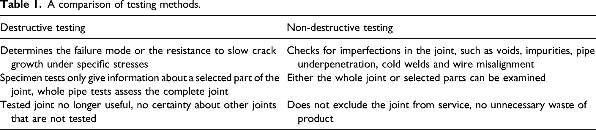
Non-destructive testing
A comparison of testing methods.
Visual inspection
Visual inspection is the most basic form of NDT. It is defined in the EN 13100-1
40
standard and can be carried out in three phases: • before welding – correct alignment and fixing, gap size, pipes cleanliness, ovality, tool marks on welded surfaces and coupler inner surface, • while welding – any unstable behaviour and indicator pins not coming out, • post-welding – wire or PE material coming out of the joint and angular pipe misalignment.
Ultrasonic testing
Ultrasonic inspection has been a widely adopted industry standard in the production of steel or aluminium components. It can be likewise used with PE. Standards that describe ultrasonic methods for EF joints are ISO/TS 16943 41 , ASTM E3170 42 (phased-array ultrasonics (PAUT)) and ASTM E3167 43 (single-crystal probe ultrasonics).
The principle of operation is to emit an ultrasonic signal with a probe touching the surface of the EF fitting; the sound propagates through the fitting and, at any boundary between media of different acoustic impedances, a reflection occurs and a part of the energy is reflected back to the probe. The rest travels on to get reflected from the inside of the pipe and reaches the probe at a later time. Any non-homogeneity or discontinuity in a material can form such a boundary. The time difference between different ultrasonic reflections establishes the depth at which the discontinuity lies. Multiple measurements are necessary to establish the exact size of a flaw, and for uniform, simple geometries such as pipes PAUT devices are used that scan a larger area at the same time and are moved around the circumference of the joint to create an image of the whole fusion zone as shown in Figure 10. One of the main assets of PAUT is that the depth of the melt zone can be determined, which means that it can warn the operator about cold welds,44,45 but other imperfections also can be detected, including particulate contamination,
46
voids,
44
pipe misalignment (both angular and incomplete insertion)
44
and wire misalignment.
44
An example image showing a complete phased-array ultrasonic scan of an EF joint. (courtesy of TWI Ltd.).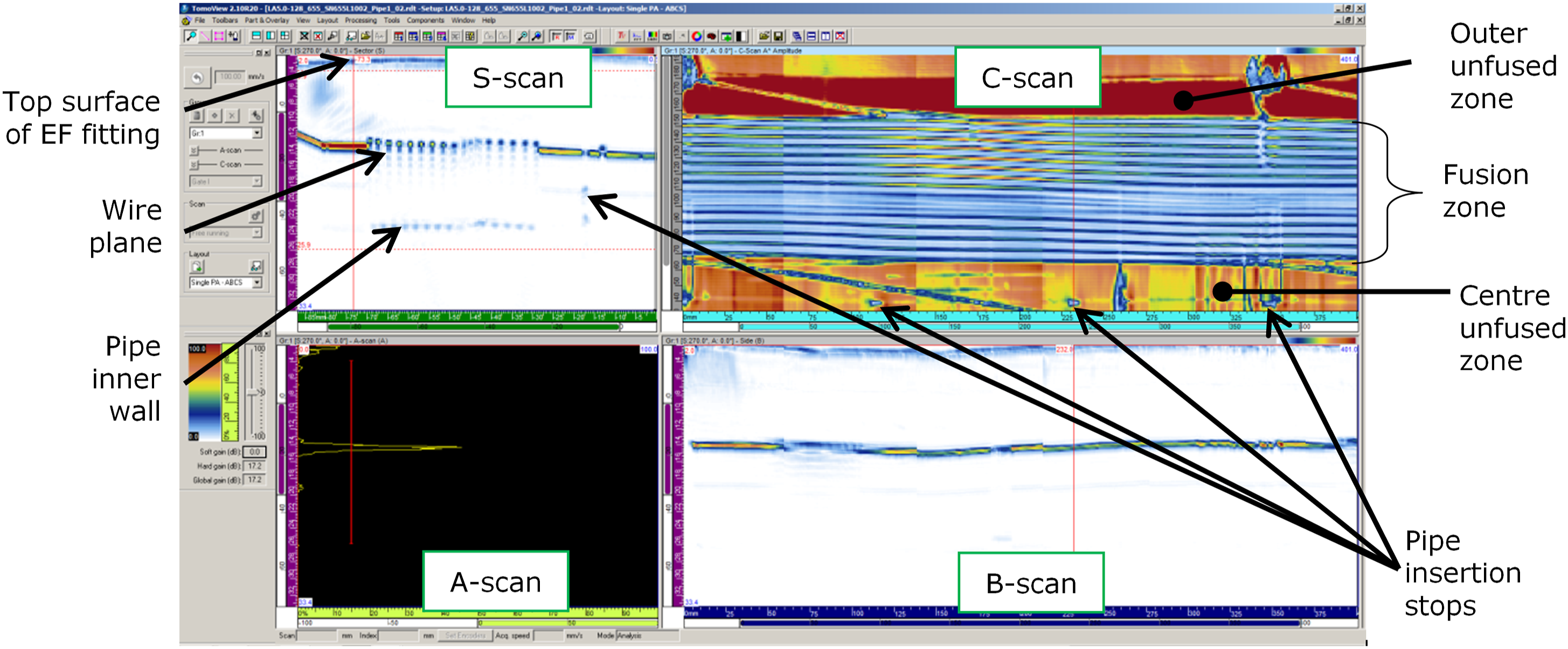
Figure 10 shows the results produced by PAUT scanners: A-scan – the result of a single measurement by a probe placed in one spot, S-scan – multiple A-scans along the length of the fusion zone, B-scan – multiple A-scans around the circumference of the joint, C-scan – multiple S-scans repeated around the complete circumference of the joint.
The ultrasonic probe and control software need to be carefully designed for EF joint inspection in order to find flaws below the heating wire coils, at the fusion interface. To get the ultrasonic energy in to the joint, the surface of the EF fitting must be covered with a coupling gel.
Microwave imaging
Microwave imaging (MI) is a technique dedicated for non-metallic materials and is described in ASTM E3102 47 for the inspection of EF joints. In its simplest form, an electromagnetic wave of a single, phase coherent frequency (5–50 GHz) is launched by a transmitter into the joint, its energy gets reflected from every interface between materials of different dielectric constant, and the reflections are detected by receivers.
Similar to ultrasonic methods, MI also needs systematic surface scanning to achieve a map of the welded joint. According to the equipment manufacturers, there is no thickness limitation, the resolution is independent of depth and the technique is capable of detecting cold welds, voids, misalignment and contamination. 48 Zhu et al. 49 also claim that MI is able to detect cold welds and grease contamination. However, the technique has not been widely adopted.
X-ray radiography
In X-ray method, the joint is irradiated by a beam of electromagnetic waves the length of 10 p.m.–10 nm. Some of the radiation is absorbed, depending on the materials density and structural composition, and the rest is caught by a detector on the other side, creating a monochromatic two-dimensional picture. This allows the operator to see any irregularities inside the object, giving a ‘photographic’ image of the joint. According to Bergman and Jacobson 50 , this technique can detect impurities, wires or pipe misalignment, voids and pipe ovality. The drawback is that melt zones are not visible on the scans, so cold welds will stay undetected, and there are safety concerns regarding using the equipment in the field.
Computed tomography is an advanced form of X-ray radiography based on multiple X-ray scans taken from different angles and combined to produce a 3D image and is widely used in the medical industry. This NDT technique has been used to inspect EF joints fairly recently. According to Baudrit et al., 51 it has the potential to detect pipe underpenetration, gap irregularities, impurities and voids and wire dislocation. The technology has not been widely adopted – the size and complexity of the necessary equipment makes it difficult to be used for in-field inspection, effectively limiting it to laboratory use.
Thermography
Real-time monitoring of temperature during welding can be a test method for plastics, even though their thermal conductivity is low (compared to metals, where this method is commonly used). Using a thermal camera or thermocouples, temperature versus fusion time is observed and can be compared with reference curves for unflawed welds.
An example result is shown in Figure 11, where the two black lines represent a good quality joint and the red line is from a flawed joint – in this case the pipe was not fully penetrated into the coupler.
45
Example of a thermal inspection result
45
(courtesy of TWI Ltd.).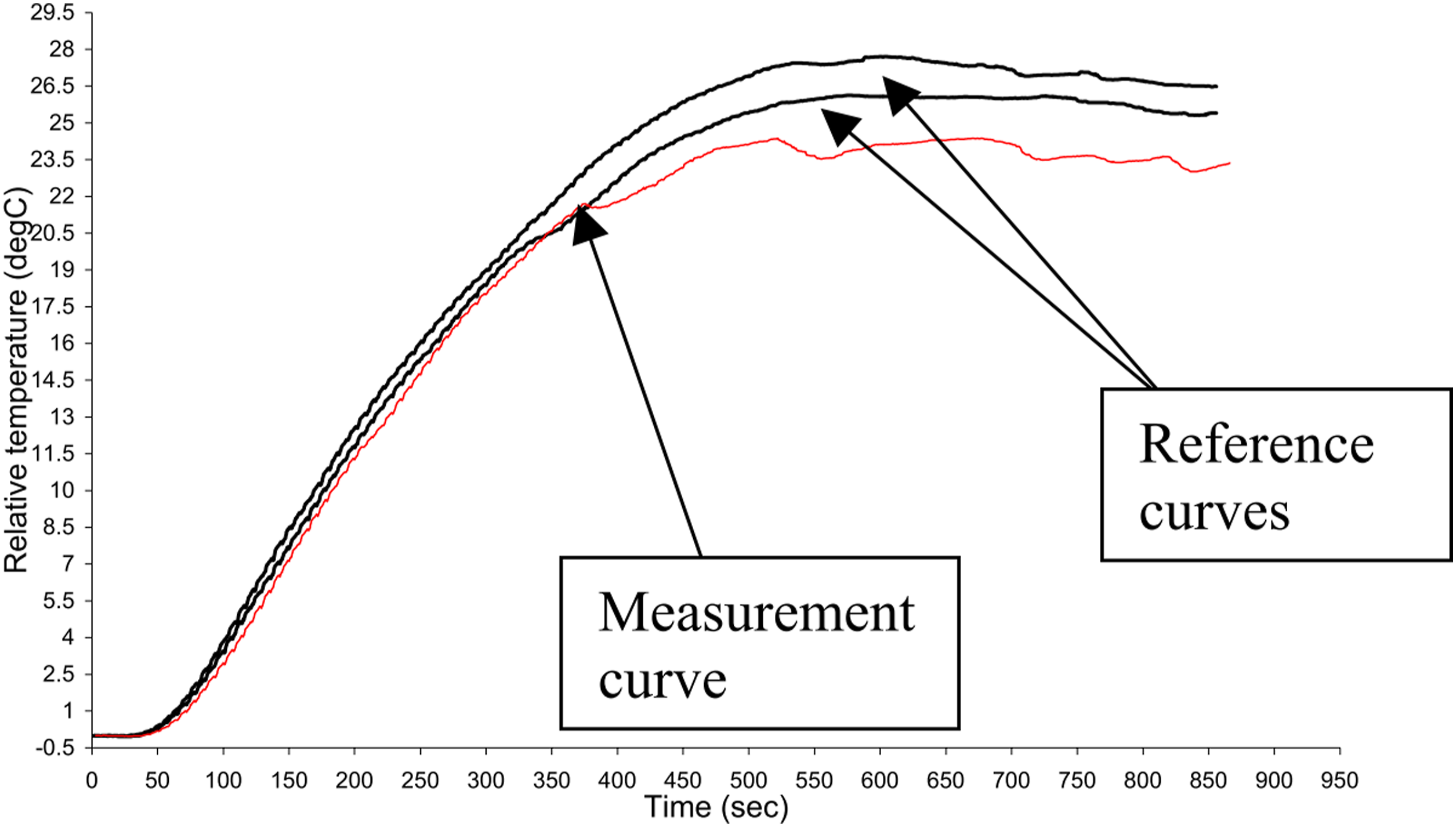
An alternative version of this method is pulse thermography where, after the welding is completed and the joint has cooled down, the coils are heated again at lower power and for a short time, so the plastic is not remelted, but a heat pattern can be caught on a thermal camera. Again, the image is compared to one from a good quality joint for deviations. This method is still at an early stage of development for electrofusion joints. 52
Terahertz
This is one of the latest inventions for NDT of dielectric materials and has recently been applied to EF joints. Terahertz (THz) is electromagnetic radiation shorter than microwaves, but longer than infrared, and most thermoplastic materials are transparent to it; the principle of operation is similar as in microwave imaging. As reported by Kremling et al., 53 it has the advantage over the ultrasonic method in that it requires no coupling medium and can go through air cavities in the scanned object, and it is also much safer for the operators than X-ray radiography, having no ionising effect. The method is not yet widely used for EF joint inspection.
Types of imperfections and their causes
Although EF welding is a fairly straightforward process, operator carelessness can cause a range of imperfections. These pose a threat to the joint integrity, because axial loads and internal pressure exert stresses on the weld interface in normal operating conditions. The most common reason of failure of EF joints has not been established; however, slow crack growth (SCG) is the most common long-term fracture mode.
A list of typical flaws that may be generated during EF welding is given in BS EN 14728 54 and the most important types are described in the sections below.
Poor fusion interface
The fusion interface is the area where the outer pipe surfaces and the fitting bore touch. Some of the typical flaws occurring at the fusion interface are given below.
Cold weld
A cold weld is defined in ISO/TS 16943 41 as:
‘insufficient joint integrity caused by the incomplete intermolecular diffusion of polymer chains for proper molecular entanglement at the joint interface due to reasons other than contamination, which does not create any NDT indication(s) at the joint interface’.
One of the reasons for cold welding is insufficient energy applied to the coils. This can happen if the manufacturer’s instructions for the welding time or current are not followed or if the clearance between the pipe and fitting is too large (e.g. as a result of overscraping), and the supplied electricity is not sufficient to fill it and form a weld. Cold joints are difficult to differentiate visually from normal ones, but their mechanical properties can be much worse – they fail in a brittle manner when subjected to bending loads. In peel decohesion tests a specimen with a cold weld will fail through the fusion interface in a brittle manner.
Such a joint may not be detected by the operator and will function in a pipeline until a sufficiently high strain is applied to it.
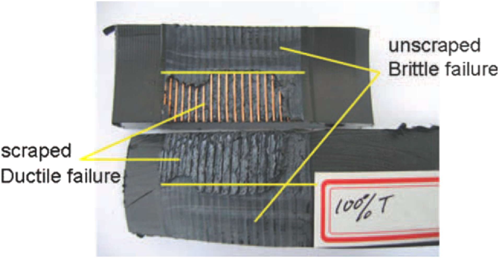
Unscraped pipes
If the pipes are not properly scraped immediately before welding, their surface contains chemicals that obstruct the molecular diffusion between the pipe and the coupler. Commonly, these substances are identified as oxides; however, according to Jacobson et al., 6 they are stearates left over from the pipe production process. Baudrit et al. 55 stated that it was carbonyl concentration that was responsible for this phenomenon, as it decreased with time near to the outer surface of the pipe because of UV radiation from the sun. A similar opinion is expressed in Nussbaum et al. 24
Joints tend to fail in a brittle manner in unscraped areas – see Figure 12. The result of a peel decohesion test performed on an EF joint coupon including a part of scraped and unscraped area of the pipe.
21
Fusion interface contamination
If dust or any other contamination (sand, water, oil, grease) settles on the scraped surface of the pipe before it is inserted into the EF fitting, this will obstruct the welding process. It is therefore very important that the scraped pipe is inserted into the EF fitting as soon as possible after scraping.
The effect of contamination on the performance of the joint is proportional to the axial length of the contaminated area, but, according to Shi et al., 21 it is most problematic close to the inner cold zone. For particulate contamination, it is also proportional to the concentration of the contamination. 56
Voids
Voids are empty spaces in the plane of the heating wire or at the fusion interface, found after welding. If they occur in the plane of the heating wire, they are normally a result of thermal shrinkage as the joint cools and solidifies and are benign. However, excessive voiding in the plane of the heating wire can be generated due to incorrect welding procedure. Voiding at the fusion interface can be due to moisture on the pipe surface.
Structural deformation
By structural deformation, it is meant that some part of the welded joint did not keep the expected form. It may include pipe underpenetration (not pushing the pipe to the centre stop), angular pipe misalignment (when the pipes are not properly clamped) or wire dislocation. Wires can change their positions in both axial and radial direction. According to Bowman, 18 it is possible when the melt pressure is too high and the melt flow pushes the wires around, sometimes resulting in short-circuiting. According to Shi et al., 21 radial dislocation tends to happen due to excessive flow of PE melt that might occur when too much melt pressure is produced.
In the case of pipe underpenetration, the PE melt might leak out of the fusion zone into the bore of the pipeline and obstruct the flow.
Other imperfections mentioned in BS EN 14728 include ‘excessive toe-in’, which means that the inserted end of the pipe has a smaller diameter than the rest of it due to release of residual stresses generated during pipe manufacture. It is more prevalent in larger diameter pipes and can result in insufficient welding pressure and leakage of molten PE into the pipe bore.
Also, if the melt indicators do not pop out, it could be because the melt pressure in the area beneath them was not sufficient. If they come out with an excessive amount of melt, this means the pressure was too high.
Finally, it is possible that some PE is pushed out of the socket, which again indicates that too much pressure was produced or there was excessive pipe ovality.
Failure modes
In normal operating conditions, when transmitting fluids from one pipe segment to another, EF joints are subject to internal pressure, which acts on the pipe bores, but also on the inner cold zone, as shown in Figure 13. This pressure results in a peeling effect occurring between the pipe surface and the fitting, which may eventually result in cracking and leaks. Another typical type of loading is in the axial direction, due to restricted thermal contraction of buried pipe and pipe bending. Failure modes of an electrofusion joint – a schematic drawing.
21
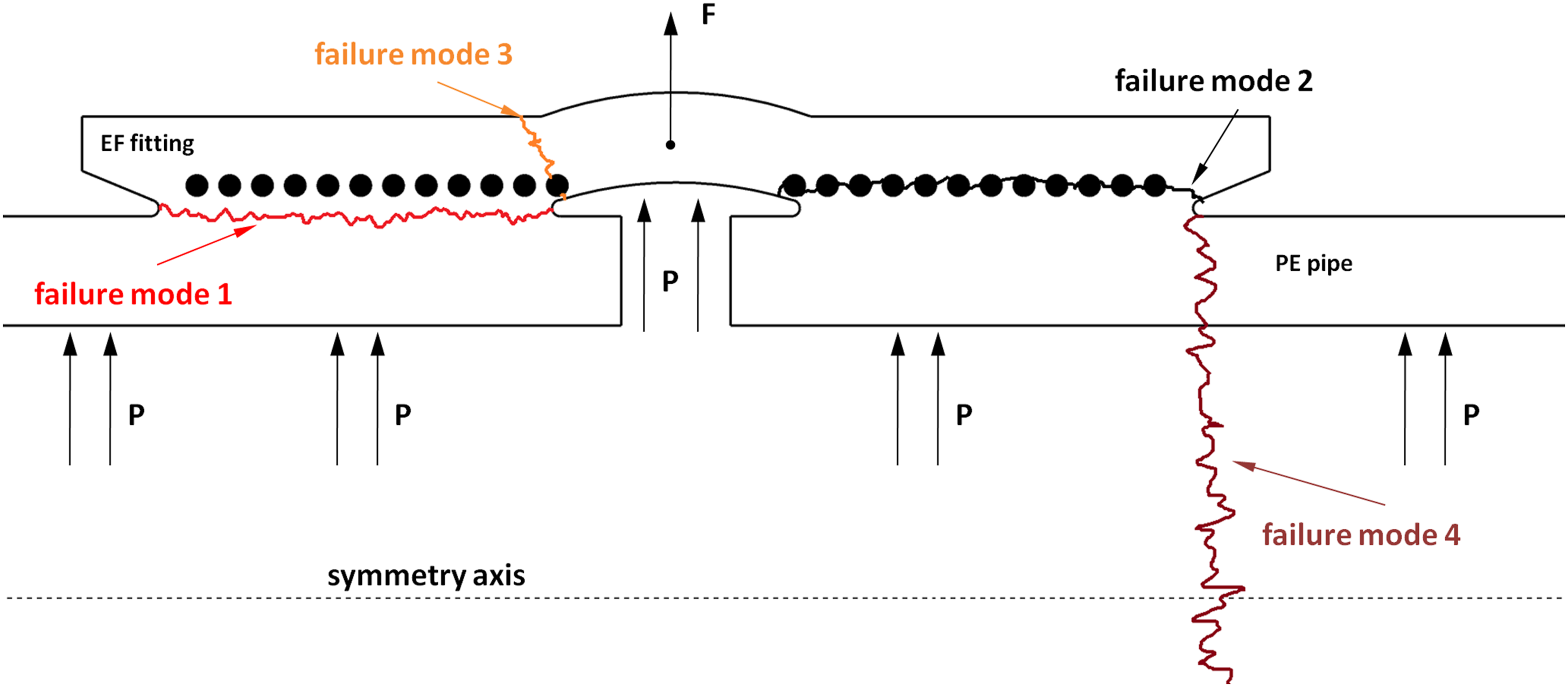
The sections below describe the possible failure modes in EF joints.
Failure mode 1 – cracking through the fusion interface
This mode is typical for peel decohesion tests when the weld interface is weak, so cold welds, contamination or unscraped pipe, for example when the fusion time is too short or there is not enough intimate contact between the mating molten polymer for molecular diffusion to happen. A specimen from such a joint fails in a brittle manner in a peel decohesion test (see Figure 14) and its long-term mechanical performance might be impaired, according to Shi et al..
21
This failure mode is recognised in peel decohesion tests by the wire imprint being barely visible, the surface is almost perfectly smooth. Example of failure mode 1 – fracture face of a cold weld subjected to a peel decohesion test. (courtesy of TWI Ltd.).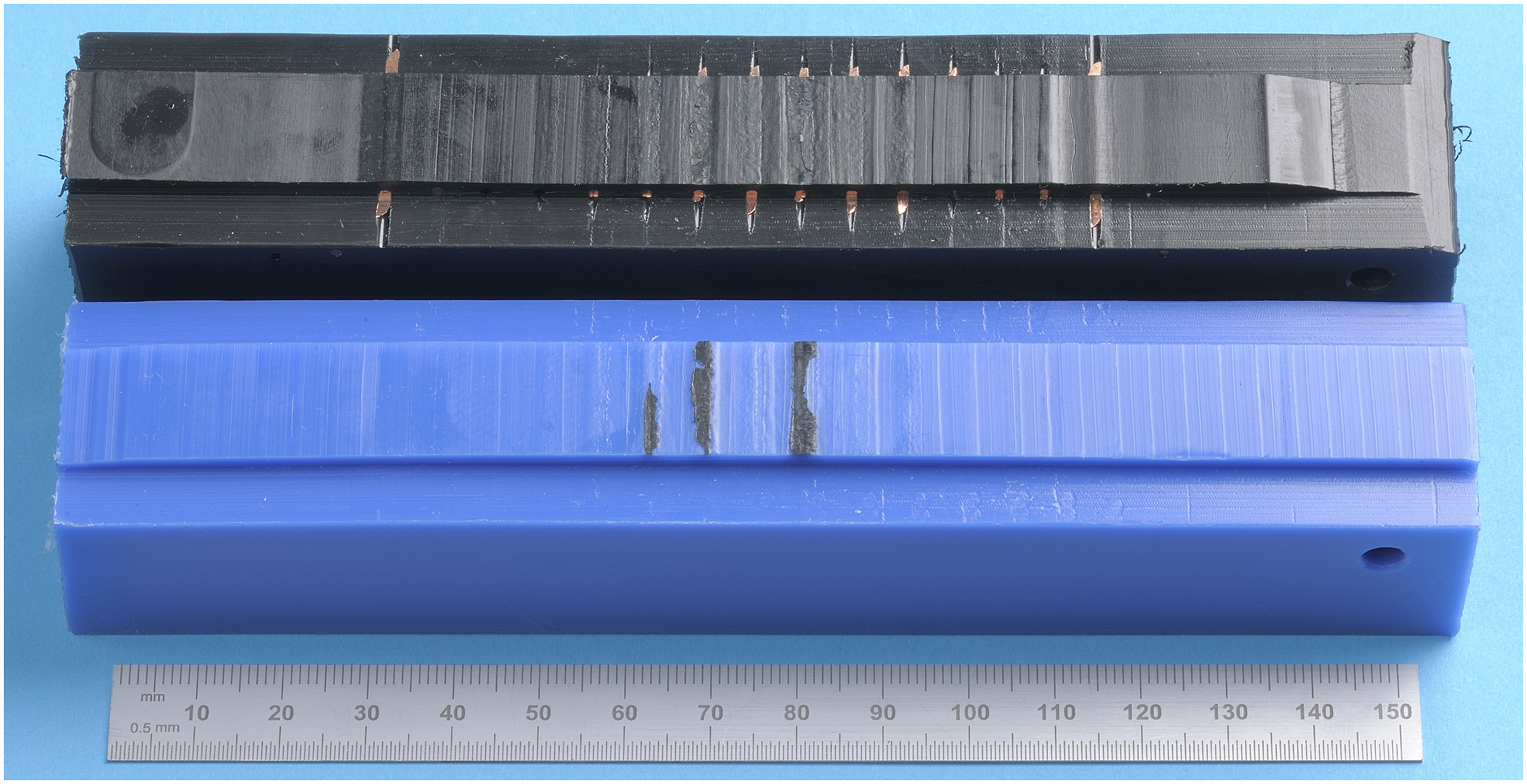
Failure mode 2 – failure through the plane of the heating wires
When there is ductile failure between the turns of the heating wire, this is the normal failure mode for correctly made joints when subjected to a peel decohesion test (Figure 15). However, if the failure mode is brittle between the turns of the heating wire, according to Shi et al.
21
it is likely to be due to heat degradation of the material because of overwelding. According to Shi et al.,
21
with increasing heating time, the most probable failure mode changes from 1 to 2, and for the 90 mm diameter joints they investigated, they were starting to see failures through the plane of the heating wire regularly when more than 55% of specified fusion time was reached. Failure mode 2 – a correctly made joint fails through the plane of the heating wires in a peel decohesion test. The wire imprint is clearly visible. (courtesy of TWI Ltd.).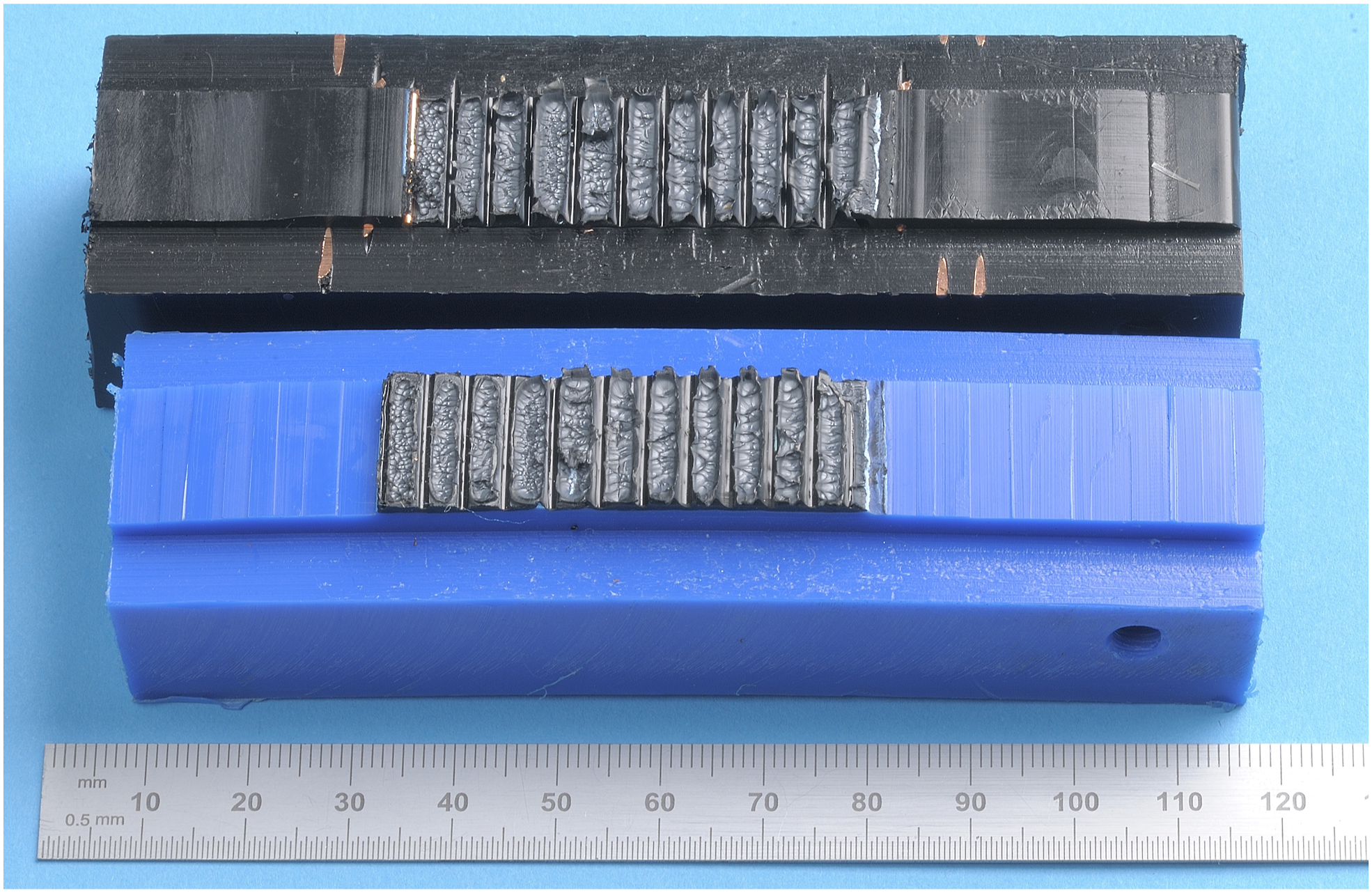
Failure mode 3 – cracking through the fitting body
This type of failure starts from one of the wires closest to the centre of the joint and propagates at an approximate angle of 70° (shown in Figure 16) through the fitting wall, resulting in a crack visible from the outside. Lever claimed this is the mode of failure encountered in long-term elevated temperature hydrostatic tests for most joints, including those made correctly,
36
a similar finding is stated in a paper by Troughton et al.
38
Additionally, Allcard and Beech
57
claimed cracks usually grow from the first turn of the heating wire coils. Shi et al.
21
suggested that, if an EF coupler had a very large inner cold zone, this would create a large stress concentration in the inner coil area, making this type of failure more probable. Example of failure mode 3 – cracking through the EF fitting of a good quality weld subjected to a hydrostatic pressure test.
38
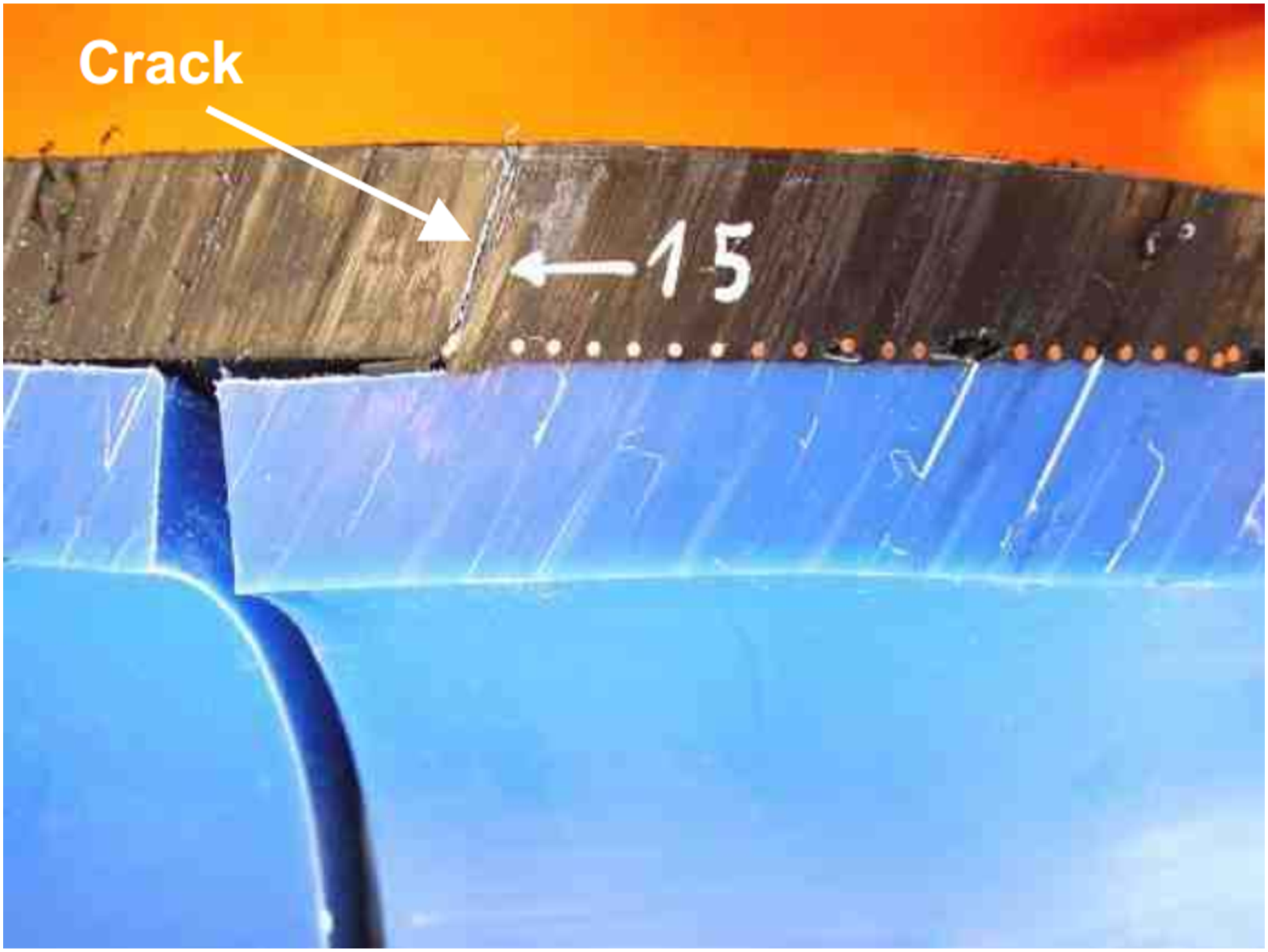
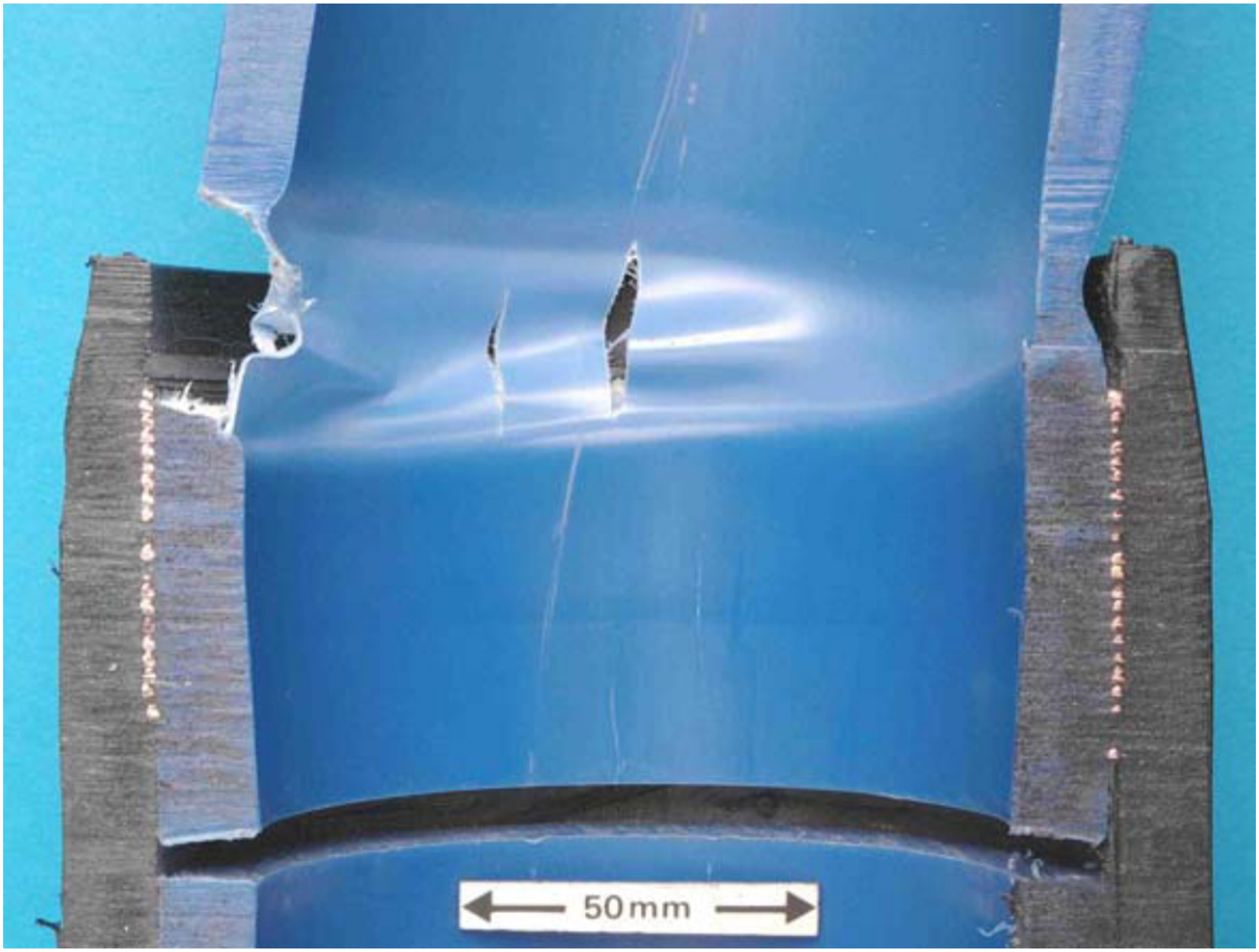
Failure mode 4 – failure through the pipe
Troughton et al.
38
found, under long-term elevated temperature tensile axial loads applied to an EF joint assembly, a crack will initiate from the outer cold zone notch, as shown in Figure 17. Example of failure mode 4 – cracking through the pipe of a good quality weld subjected to a constant long-term axial load.
38
Stress modelling of electrofusion joints
There are few references in the literature on modelling the behaviour of completed electrofusion joints under stress. Three are described below:
Zahedi et al. simulated stresses in joints buried in soil and under internal pressure from normal operating conditions. They found that maximum von Mises and axial stresses occurred in the middle of the socket’s internal surface and decreased radially with the distance from the pipe axis. Also, the stresses were well below the allowable value for a working life of 50 years at 35°C of PE100. The authors pointed out that the cold zones were subjected to large stresses, while fusion zones were relatively unstressed. 58
Troughton et al.
38
modelled the stresses generated in EF joints during the whole pipe tensile creep rupture test (Figure 18(a)) and a hydrostatic pressure test (Figure 18(b)). In the former, the largest stress concentration appears in the pipe at the outer cold zone notch (leading to failure mode 4, see Figure 16), in the latter it occurs in the coupler at the inner cold zone notch, resulting in failure mode 3.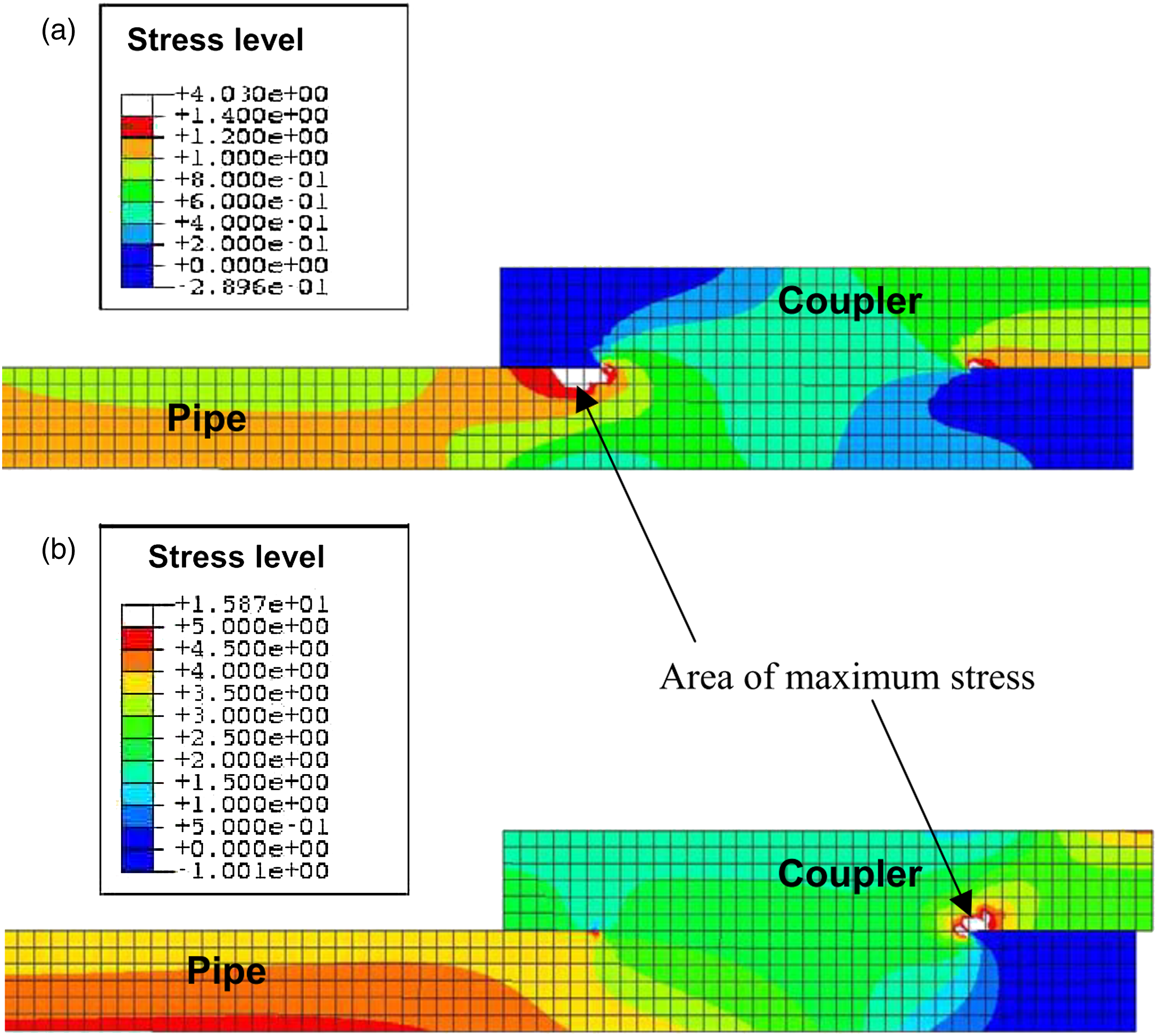
Simulations of hydrostatic pressure tests carried out by Lever 36 had similar results: the maximum stress concentration was localised at the onset of the inner cold zone, at the first turn of the heating wire. Troughton and Lever both compared their simulations with experimental tests and concluded that the results were matching.
Conclusions
There is a strong push towards the development of reinforced thermoplastic pipes and their market share is predicted to grow further. This review has described the state of the art in RTPs and electrofusion joining. It is suggested that these two technologies can be successfully merged, even though this idea has not been widely applied yet. It can be seen that there is very little academic content on RTPs, most information has come from pipe manufacturers. Electrofusion joining, on the other hand, is a well-researched and described process, but it can be expected that EF joints in composite pipes will behave in a different way compared to EF joints in unreinforced PE pipes and problems might be encountered that are not relevant to standard plastic pipes. The potentially most fruitful areas of development include stress modelling to predict joint performance and failure modes at much lower cost than extensive experimental testing.
Footnotes
Acknowledgements
This publication was made possible by the sponsorship and support of the Non-metallic Innovation Centre (NIC) and Engineering and Physical Sciences Research Council (EPSRC). The work was enabled through the National Structural Integrity Research Centre (NSIRC), a postgraduate engineering facility for industry-led research into structural integrity established and managed by TWI through a network of both national and international universities.
Declaration of conflicting interests
The author(s) declared no potential conflicts of interest with respect to the research, authorship, and/or publication of this article.