
Abstract
Carbon fiber-reinforced polyetheretherketone (CF/PEEK) composite offer lightweight, high strength and toughness by combining benefits of resin and fiber materials. However, current shaping methods face challenges such as forming difficulties, inconsistent shapes, and significant mechanical damage. Herein, a CF/PEEK composite thermoforming device were designed. Thermoforming device employs two heating molds (crimping mold at 310°C and roll pipe mold at 400°C) and a coiling roller operating at 45 rpm to enable automatic and efficient continuous production of composite pipes with diameters ranging from 3 to 5 mm. High-strength composite pipes retain excellent thermal stability during shaping, with commendable mechanical properties-tensile strength of 1467 N (decrease of 8.8 %) and specific stiffness of 1.61 × 10⁶ N·m/kg, 35-fold increase. Furthermore, stronger braided winding points were introduced into hollow CF/PEEK truss to enhance their strengths, with radial compression strength of node-reinforced truss structure is 550 N (improved by 151 % compared with that of a single composite pipe). This node-reinforced hollow CF/PEEK truss, with its ultra-lightweight and high tensile/compressive strength, significantly expands application potential of CF/PEEK composite materials.
Keywords
Introduction
Composite materials are rapidly advancing due to their excellent specific strength and problem-solving capabilities,1,2 especially as aerospace and high-end industries rise in prominence.3–5 Carbon Fiber (CF) refers to a high-performance, lightweight material made primarily from carbon atoms. It is produced through process of polymerization and subsequent thermal treatment (carbonization), typically from organic precursors such as polyacrylonitrile (PAN). Carbon fiber reinforced polymer composite (CFRP), the most commonly used and effective reinforcing material, stand out for their outstanding capabilities in various aspects,6,7 such as high strength, low density, and excellent corrosion resistance.8–11 Polyetheretherketone (PEEK) is an aromatic crystalline thermoplastic polymer material, possess superior overall performance, which can be laminated with high performance fiber materials to prepare reinforcing materials. 12 As a result, CF-reinforced PEEK composites hold great potential for applications requiring lightweight and high strength materials.13,14
Currently, most of lightweight CF/PEEK truss structures are chemically bonded with poor joint stability, which affects the overall performance. 15 Differently, fiber materials in textile can intertwine to create interlocking structures, greatly enhancing product mechanical properties. Through packaging, twisting, and interlacing, carbon fibers can be wrapped, wound, and woven to form an interlocking structure, greatly enhancing bonding strength within connection points.16,17 Therefore, incorporating woven textile structures into CF/PEEK composites have potential in effectively enhance mechanical properties of traditional CF/PEEK fiber materials. 18
Additionally, high temperature shaping is essential for CF/PEEK composites to achieve their optimal properties and morphology. 19 However, current fabrication strategies of CF/PEEK composite material still suffers from shaping difficulties and a single product category. 20 Traditional shaping devices often cause significant mechanical damage to materials. Defects can cause damage or deformation of CF/PEEK during shaping, 21 temperature and pressure are accurately controlled to ensure uniform and appropriate hot pressing of prepreg tape, reducing defects caused by temperature gradients or uneven pressure. 22 Therefore, it is essential to develop a heated shaping device and optimize heating solutions, including simulations of molding temperature, molding distance, and curling speed. Therefore, shaping device of CF/PEEK should be versatile, capable of shaping CF/PEEK composites in various shapes, sizes, and functions.
Hence, based on textile winding strategy, a novel node-reinforced CF/PEEK composite material was developed. Through incorporation of winding structures into truss design, mechanical properties of hollow composite materials are significantly improved. 23 A heating shaping device designed to meet production requirements and process conditions has been produced. 24 Meanwhile, an annular high-temperature ceramic heating pipe is preheated for a two-step shaping process, ensuring the node-reinforced CF/PEEK composites possessed adequate shaping time. These novel node-reinforced CF/PEEK composites were prepared in a convenient and efficient manner, offering a new option for advancing light-weight, high-strength composite materials.25,26
Experimental
Experimental Materials
Carbon fiber composite prepreg tape was used for this research: CF/PEEK T700 prepreg tape (bandwidth 12 mm, thickness 0.2 mm. Melting temperature 343°C, from Toray, Japan); CF/PEEK prepreg tape resin content was 35-50 %, and fiber volume content was 45-59 vol %. CF/PEEK composite pipe (diameter 2–4 mm, wall thickness 0.16 mm, by carbon fiber composite prepreg tape heating mold hot shaping). High performance acrylic AB structural adhesive, provided by Guangdong Hengda New Material Co., Ltd. Annular high temperature ceramic heating pipe, provided by Yancheng Songtai Electrical Equipment Factory. Enhanced Kraft Casting Glue, 150 degree temperature resistance, provided by Dongguan Guangyuan Seal Technology Co., Ltd.
Preparation of PEEK carbon Fiber Pipe
To prepare CF/PEEK hollow pipes, prepreg tape was shaped at high temperature using a heating mold shaping device. Unlike conventional shaping methods (such as compression molding and extrusion molding), new shaping device used an annular high-temperature ceramic heating pipe, with the temperature controlled by a precise temperature controller. Prepreg tape is wound into coiler and pulled forward at a constant speed (45 rpm) by controlling reverse rotation of two coiler rollers with a motor. Crimping mold preheats prepreg tape to above 300°C, causing thermal expansion and internal stress as the temperature increases. Prepreg tape gradually softens, reducing its hardness to meet bending and shaping conditions. Roll pipe mold is heated to melting temperature of prepreg tape (above 400°C). As temperature continues to go up, PEEK component gradually melts and decomposes, material is further heated in the die to achieve shape of plastic mold. By controlling heating temperature and crimping speed, heating time and plastic holding time are regulated to heat and melt prepreg tape, shaping a CF/PEEK pipe. Based on width (12 mm) and thickness (0.2 mm) of prepreg tape, inner diameter of heating mold (4.2 mm), diameter of resulting composite pipe is calculated to be 4 mm.
Comparison of new and traditional Molding Methods
Comparison of molding method performance.
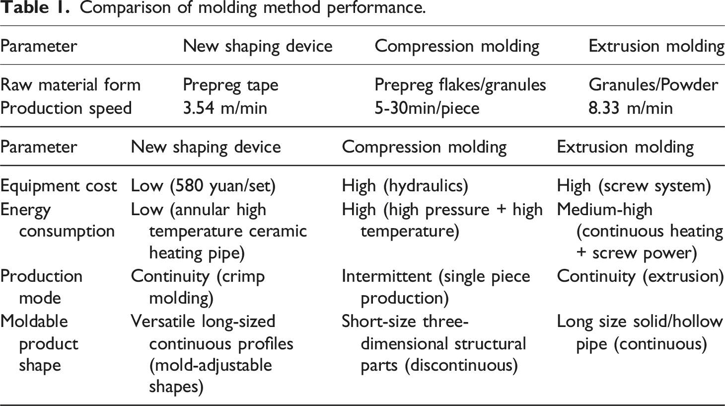
New shaping device offers superior cost efficiency, process flexibility, and continuous production capabilities compared to conventional shaping methods like compression/extrusion molding, proving ideal for medium-scale manufacturing of elongated continuous products. However, its constrained capacity for creating intricate 3D geometries and achieving industrial-scale ultra-high-speed production necessitates hybrid strategies combining conventional methods for specialized applications.
For study of conventional molding methods, Xie et al. performed compression molding of carbon fiber prepregs, 27 Sun et al. introduced extrusion molding proces, 28 and Antolin-Urbaneja et al. carried out experimental characterization of screw-extruded carbon fiber prepregs. 29 Comparing mechanical properties, cost-effectiveness, and production efficiency of new and traditional methods highlights their respective advantages, limitations, and practical feasibility.
New shaping device employs a prepreg tape lamination process, achieving superior mechanical properties with a tensile strength of 1489 MPa and a flexural strength of 4390 MPa. This outperforms compression molding (tensile strength of 780 MPa) and extrusion molding (tensile strength of 650 MPa), which suffer from isotropic properties and fiber damage defects, respectively. While compression molding achieves low porosity (<1 %) through high-pressure densification, new device excels in interlayer bond strength, fatigue resistance, and stability under complex loads.
Cost-wise, new shaping device is highly economical for low-volume production, with equipment costs of 580 yuan and mold costs of 500 yuan-only 0.5-1 % of compression molding’s costs. It also uses less energy (200 W) and reduces material waste (22 % less) despite higher prepreg tape costs (800 yuan/kg). In contrast, extrusion molding has the lowest cost in high-volume production (10–15 yuan/m), but high equipment investment (200,000–500,000 yuan) and potential reworking due to porosity (2–5 %) add hidden costs.
In terms of productivity, new shaping device allows flexible, low-volume production with continuous coiling (3.54 m/min) and quick die changes (<5 min). Extrusion offers high-speed, high-volume production (8.3 m/min), while compression molding is slower due to intermittent operations (5–30 min/piece) and long die changes (30–60 min).
In conclusion, new shaping device offers an ideal balance between high mechanical performance and small-volume economics, making it suitable for industries like aerospace and high-end sports equipment. Compression molding works well for custom key components with low porosity, and extrusion molding is more cost-effective for large-scale production. This comparison provides a clear guide for technology selection, emphasizing new device’s unique advantages in specific applications.
Performance Evaluation
Prepreg tape and composite pipe 10 cm were taken respectively. Mass was weighed by electronic analytical balance, and volume was calculated by formula (1) and (2):

Specific stiffness of composite material is a crucial indicator of its mechanical properties.
30
Specific stiffness of CF/PEEK prepreg tape is usually between 2 × 10⁴-7 × 10⁴ N·m/kg. After high temperature pipe is formed, specific stiffness can be calculated by formula (3), (4), (5):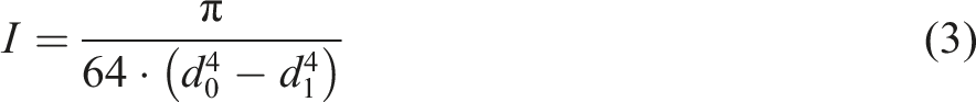
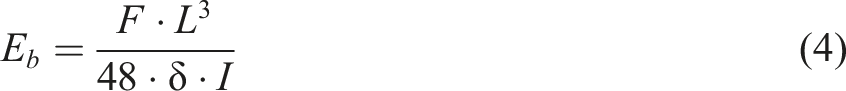
P represents specific stiffness of material, ρ refers to density of material; composite pipe is 10 cm long and three-point bending span is 32 mm. Bending stiffness of composite pipe is 4.93 GPa, and specific stiffness is 1.61 × 10⁶ N·m/kg. Average specific stiffness of composite pipe is 35 times greater than prepreg tape.
Characterization and testing
FH series composite cutting machine was used to cut material into samples for performance testing. Sample sizes were adjusted according to the specific test conditions and in accordance with ASTM D3039 (tensile properties of polymer matrix composites) and ASTM D3410 (shear properties of polymer matrix composites). 31 An electronic universal testing machine (Instron 3365, ITW) with a load capacity of 10 KN was used for testing. Tensile test samples had a length of 200 mm, while the widths of prepreg tapes were 4 mm, 6 mm, and 12 mm. Width of composite pipes was 4 mm. Tensile test was conducted at a strain rate of 2 mm/min with an inlet force of 10 N. Bending test used a compression rate of 1 mm/min, with composite pipe spans of 32 mm, 64 mm, and 128 mm, and span-to-thickness ratios of 8:1, 16:1, and 32:1, respectively. To ensure data accuracy, at least five samples were recorded for each test. Surface morphology and tensile fracture surfaces of CF/PEEK prepreg tape and composite pipe were observed using a German Sigma300 scanning electron microscope. 32 Infrared spectra of prepreg tape and thermoformed composite pipe were analyzed using Nicolet6700 Fourier infrared spectrometer from American Thermoelectric Company. Weight changes and heat flow signals of prepreg tape and composite pipe were measured using METTLER TGA/DSC3+ synchronous thermal analyzer from the Swiss Mettler Toledo Group. 33 COMSOL Multiphysics software, developed by Swedish company COMSOL, was used to simulate heat transfer in two molds during composite pipe thermoforming.
Results and Discussion
A thermoforming device was developed for production of lightweight and high strength CF/PEEK composite pipes.
34
Prepreg tape exhibits exceptional toughness and can be bent for up to a week without sustaining damage.
35
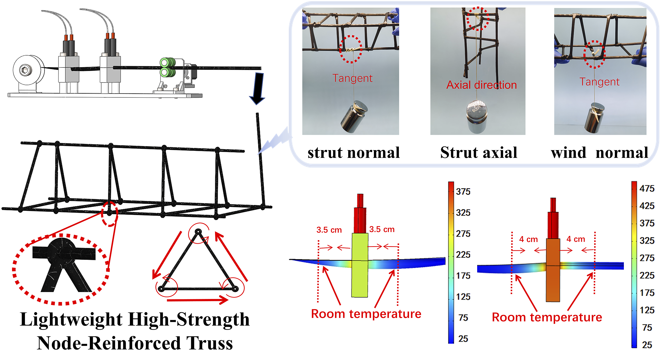
Figure 1(a) presents heating shaping process. As roller moves forward, shape is maintained without adhering to mold, ensuring efficient and continuous preparation of CF/PEEK composite pipe. Using two molds with different heating temperatures sequentially facilitates complete melting and flow of CF/PEEK resin, resulting in more uniform resin distribution and a better shape after shaping. Heating mold is equipped with a thermostat that allows real-time observation and control of both heating pipe and mold temperatures. Figure 1(b) and (c) presents CF/PEEK composite pipe thermoforming device model and physical object. After thermoforming, composite pipe maintains excellent bending stiffness, load-bearing capacity without deformation, and retains its light weight, high strength, high temperature resistance, and corrosion resistance. This opens up numerous new application possibilities. Preparation and application of CF/PEEK composite pipe: (a) Preparation process of CF/PEEK composite pipe. (b) CF/PEEK composite pipe thermoforming device model. (c) CF/PEEK composite pipe thermoforming device physical object. (d) CF/PEEK composite pipe truss winding point structure.
New shaping device unit cost 580 yuan, energy cost is 0.272 yuan/h (including motor operation and dry burner tube heating); and raw material is prepreg tape (800 yuan/kg, equivalent to 3.2 yuan/m). It is worth noting that, through process optimization, 1 m prepreg tape can be coiled to prepare 1.2 m hollow pipe. Operating at 212 m/h, process achieves a comprehensive production cost of 565.61 yuan/h (excluding equipment costs), translating to 2.67 yuan/m for hollow pipe fabrication. This represents a 16.6 % cost reduction compared to raw material expenses alone. This system can produce various shapes and sizes by simply replacing plastic and curling molds. However, challenges remain in scaling up production and optimizing molding process. Future efficiency gains could be achieved by: improving stable curling speeds, integrating feeding and curling operations, and implementing automation. These advancements remain crucial for enabling high-volume industrial production of CF/PEEK. CF/PEEK composite pipes are currently used in the customized production of small diameter precision pipes (medical catheters, fiber optic sheaths); small batch high value-added products (aerospace components, truss structural). As illustrated in Figure 1(d), lightweight and high-strength CF/PEEK composite pipe is an ideal substrate for large-scale, three-dimensional braided hollow truss structures. 36
Heating temperature and heat transfer characteristics of shaping must be determined based on glass transition temperature (143°C), melting temperature (343°C), and decomposition temperature (560°C) of CF/PEEK material.37,38 Crimping mold is utilized for preheating and setting, with a preferred temperature of around 310°C, slightly below melting point of 343°C. Roll pipe mold is used for shaping, with an optimal temperature of 400°C to fully melt resin for even flow and firm adhesion. Mold thermal simulation experiment is then conducted.
An annular high-temperature ceramic heating rod was used to heat mold, with capability to reach temperatures up to 600°C. SolidWorks 3D modeling software is utilized to create models of crimping mold and roll pipe mold. 3D Model is imported into COMSOL for material division, parameter assignment, grid processing, and heat transfer simulation. The gridded results are illustrated in Figure 2(a) and (d). Simulation is conducted separately for crimping mold and roll pipe mold, considering both single and double heating pipes configurations. Given that PEEK has a melting temperature of 343°C, optimal molding temperature ranges from 310°C to 400°C, accounting for environmental heat loss. Heating pipe in curling mold is set to 400°C, while heating pipe in coiling mold is set to 500°C. CF/PEEK thermoforming mold heating temperature simulation diagram: (a) The normal fineness of the curling mold is gridded. (b) Temperature simulation of double heating rod curling die. (c) Single heating rod curling mold temperature simulation. (d) Normal fineness gridding of the coiling die. (e) Double heating rod coiling die temperature simulation. (f) Single heating rod coiling die temperature simulation. (g) Unilateral heating bonding process.
Aforementioned discussion indicated that maximum temperatures for double-tubes and single-tube heating of crimping mold are 377°C and 323°C, respectively (Figure 2(b), (c)), while those for roll pipe mold are 473°C and 417°C, respectively (Figure 2(e), (f)). When curling prepreg tape access to molds, edge temperature should be higher than other parts to ensure complete resin melting and stronger bonding. In crimping mold, temperature at bonding position is 15°C higher than at center, while in roll pipe mold, it is 23°C higher (Figure 2(g)). Consequently, considering comprehensive molding temperature conditions, single-rod heating (Figure 2(c), (f)) with symmetrical placement is use.
Heating mold is heated using single-tube, with two molds positioned symmetrically. Crimping mold was heated to 400°C, while center molding temperature reached 323°C. Roll pipe mold was heated to 500°C, and center molding temperature was 417°C. To avoid impact between two heating molds, it is essential to calculate molding distance between them.
In order to reduce production costs, avoid material wasted and improve mechanical properties of composite pipe, optimized adjustment of molding distance between two molds is essential. Moreover, cooling of materials between two heating molds was necessary to prevent resin flow and unwanted deformation. After establishing heating method and temperature, simulation of thermoforming process to determine optimal spacing between two molds. Temperature gradient distribution between two heating molds is crucial for material shaping and temperature control. Heating simulation results showed that for crimping mold, material cools to near room temperature at above 3.5 cm from mold (Figure 3(c)); for roll pipe mold, cooling occurs at above 4 cm from mold (Figure 3(d)). Therefore, to ensure that two molds do not affect each other temperature environment and to prevent unnecessary deformation, spacing between two heating molds should be at least 7.5 cm. Temperature simulation of CF/PEEK thermoforming process: (a) Normal fineness gridding of curling process. (b) Ultra-fine fineness gridding of the coiling process. (c) Temperature simulation of single heating rod curling process. (d) Temperature simulation of single heating rod coiling process.
After designing shaping device and optimizing heating regime, CF/PEEK composite pipes were prepared. Both prepreg tape and composite pipe were characterized and tested. Surface morphology of prepreg tape and composite pipe was examined using scanning electron microscopy. Figure 4(a) and (b) indicated that comparison of surface morphology before and after molding. Scanning electron microscope and EDS images of prepreg tape and composite pipe are shown in Figure 4(c) and (d), respectively. These images indicated that after heating, carbon content of surface layer increases from 79.3 % to 82.1 %, while oxygen content decreases from 15.4 % to 14.5 % after heating. Surface grooves of composite pipe increased significantly and PEEK resin was exposed to high temperatures, which surface color deepened. After flow and curing, molecular chains are crosslinked at high temperature, shaping a stronger three-dimensional network structure.
39
Significantly improves hardness and stiffness of prepreg tape. Characterization of prepreg tape and composite pipe: (a) Surface morphology of prepreg tape. (b) Surface morphology of composite pipe. (c) SEM surface morphology and EDS of prepreg tape. (d) SEM surface morphology and EDS of the composite pipe. (e) Prepreg tape TG and DTG. (f) Composite pipe TG and DTG. (g) TG comparison of prepreg tape and composite pipe. (h) DSC comparison of prepreg tape and composite pipe.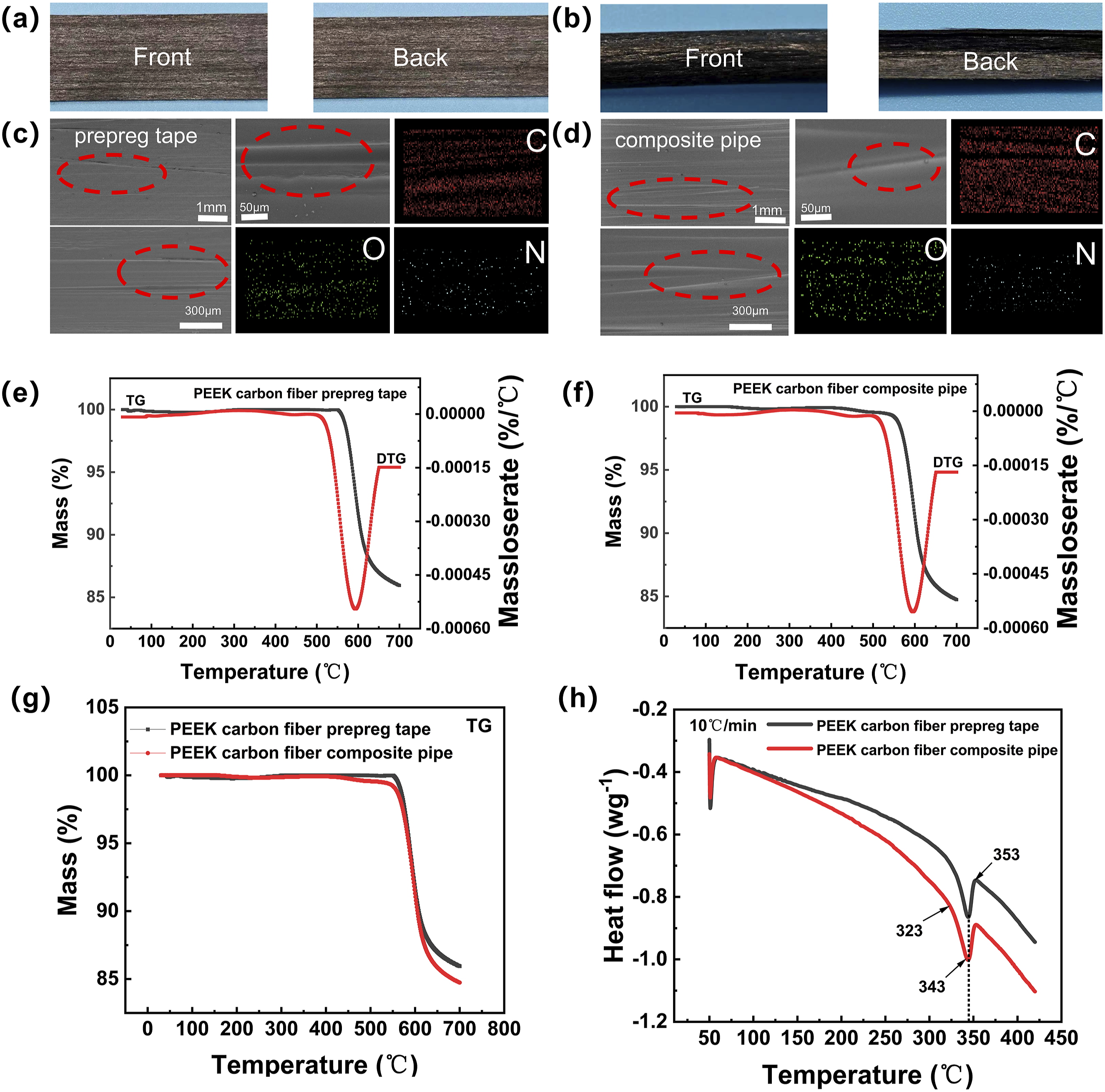
Figure 4(e), (f), and (g) displayed TG experimental results for prepreg tape and composite pipe. Indicated that both prepreg tape and composite pipe in dry nitrogen decomposition onset temperature at 515°C, rate of quality degradation is fastest at 600°C and quality changes tend to stabilize at 640°C. In the mid-to-high temperature range, PEEK resin undergoes significant quality loss due to chain structure rupture and oxidative degradation. After experiments, quality loss of composite pipe is greater than that of prepreg tape, mainly originating from differences in its structure, molding process and material thermal stability. Firstly, during high-temperature molding of prepreg tape into composite pipes, PEEK resin undergoes melting, altering carbon fiber-PEEK matrix interface and disrupting original composite structure. Concurrently, volatile components (including solvents, plasticizers, and unreacted monomers) are released, leading to measurable mass loss. Secondly, increased pipe wall thickness leads to more complex thermal dynamics during heating. Resulting thermal gradient causes higher inner-layer temperatures, accelerating matrix decomposition and volatilization. Finally, PEEK in prepreg tape exhibits higher crystallinity, enhancing its thermal stability. In contrast, PEEK matrix in composite pipes develops lower crystallinity during molding and cooling, reducing its thermal resistance and leading to increased decomposition rates during subsequent heating, ultimately resulting in greater mass loss. Aforementioned discussion indicated that composition and properties of material remain unchanged, and mass loss of composite pipe exceeds that of prepreg tape. Figure 4(h) presents differential scanning calorimetry (DSC) results for prepreg tape and composite pipes. Melting of PEEK is an endothermic process. Carbon fiber primarily influences mechanical properties and thermal conductivity of materials. In DSC curve, glass transition temperature of material is typically indicated by broad slope change. Specifically, slope of curve increases at 323°C, while peak observed at 343°C represents melting point of PEEK, confirming that PEEK undergoes a melting process at this temperature. 40 Endothermic peak corresponds to transition of PEEK from solid to liquid state. Recovery to normal slope at 353°C signifies the end of melting process, with material heat flow returning to baseline. 41
Prepreg tape and composite pipe were tested as shown in Figure 5(a) and (b) (tensile test diagrams), Figure 5(d) and (e) (three-point bending test diagrams), and Figure 5(c) (Fourier-transform infrared spectrum diagram). Changes in mechanical properties before and after heating were assessed using three-point bending and tensile tests. Figure 5(f) presents experimental results of Fourier-transform infrared spectroscopy for prepreg tape and composite pipes. Absorption band at 1650 cm−1 corresponds to vibration of ketone hydroxyl group, while absorption bands at 1598 cm−1 and 1490 cm−1 are attributed to ring vibrations of benzene ring. Additionally, absorption band in range of 1309 to 1160 cm−1 is associated with aromatic ether. Infrared absorption peaks for various chemical bonds are as follows: C = C bond between 1600 and 1750 cm−1, C-H bond between 2700 and 3100 cm−1, C≡C bond between 2100 and 2260 cm−1, and C-O bond between 1050 and 1300 cm−1.
42
By comparing changes in characteristic peaks before and after thermoforming, it was observed that prepreg tape and composite pipe did not undergo any chemical reactions at high temperature, which corroborates results obtained from SEM and EDS tests. Resin melted and solidified at high temperature, but no chemical reactions were observed. Mechanical properties test diagram and spectrum of prepreg tape and composite pipe: (a) Tensile test of prepreg tape and composite pipe. (b) Prepreg tape and composite pipe drawing diagram. (c) Fourier transform infrared spectroscopy experiments of prepreg tape and composite pipe. (d) Three-point bending diagram of composite pipe. (e) Three-point bending experiment of composite pipe. (f) Comparison of infrared spectra of prepreg tape and composite pipe.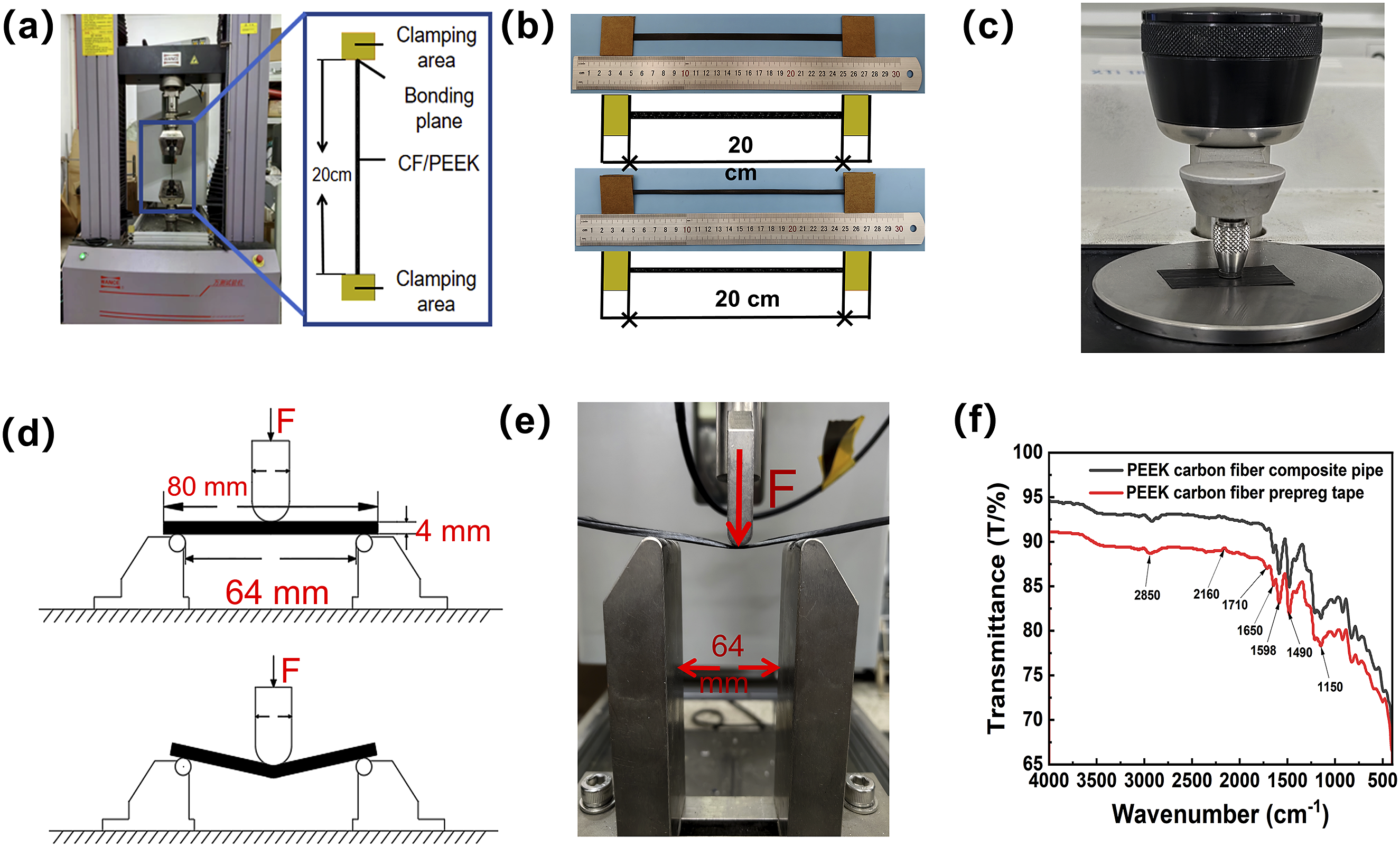
Based on weight and volume measurements, densities of prepreg tape and composite pipe were 1.24 g/cm3 and 3.06 g/cm3, respectively. Indicated that, after thermoforming, material density was significantly enhanced, resulting in a more compact structure and markedly improved strength and rigidity.43,44
Figure 6(a) and (b) illustrates truss structure exhibits excellent mechanical properties throughout woven winding process and across multiple axial directions. Specifically, CF/PEEK hollow pipes utilizes braided winding technology, which improves bearing capacity and deformation resistance of structure.
45
Additionally, introduction of woven interlocking structure optimizes stress distribution at truss connection points and enhances overall stability and stiffness of structure.
46
These improvements effectively enhance performance of truss beams under various load conditions, including bending moment, shear force, and axial force. Figure 6(c) demonstrated tensile fracture surface of prepreg tape and composite pipe. Fibers in fracture surface of prepreg tape exhibits clear stratification, with an irregular fracture surface and no distinct fracture origin, suggesting an absence of stress concentration and relatively uniform stress distribution.
47
Fracture surface of composite pipe appears flat and granular, indicating that after heating and curing of resin matrix, stress concentration develops within material due to axial grooves. Indicated in fractures that propagate outward from cracks, leading to a reduction in tensile strength.
48
Mechanical properties test results and cross-section morphology of prepreg tape and composite pipe: (a) Flexural capacity of truss beam in axial normal direction. (b) Schematic diagram of truss structure winding. (c) Cross-sectional morphology of prepreg tape and composite pipe fibers. (d) The bending resistance diagram of prepreg tape and composite pipe. (e) Tensile strength of prepreg tape with different widths. (f) The tensile strength of prepreg tape and composite pipe with the same width. (g) The bending strength of composite pipes with different spans. (h) Axial/radial compression strength of composite pipes and trusses.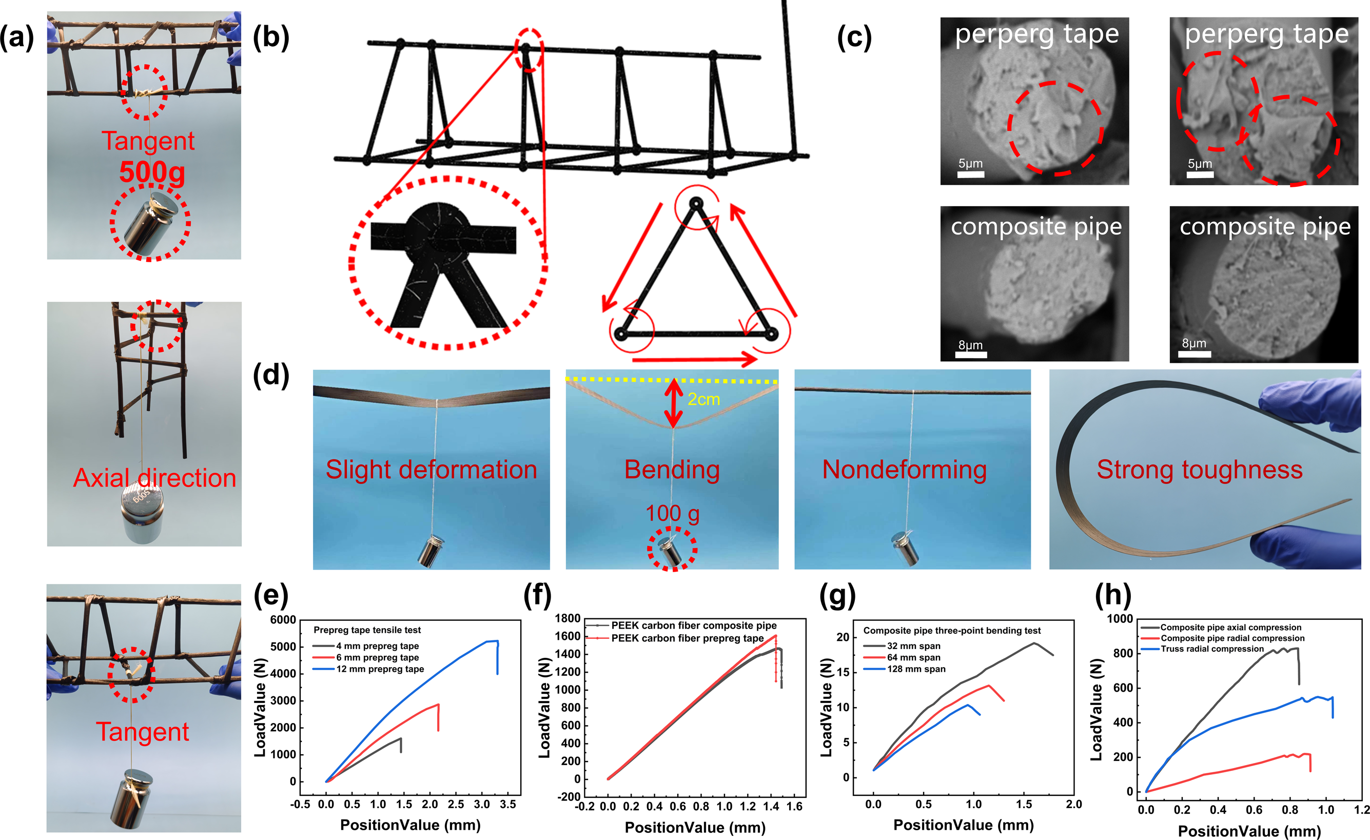
Figure 6(d) demonstrated that under the same load, prepreg tape experiences significant deformation, whereas composite pipe can bear the load without deformation. Indicated that composite pipe exhibits a substantial improvement in bending strength after thermoforming. Prepreg tape exhibits excellent toughness but is insufficient in stiffness and shear resistance. 49 Figure 6(e) and (f) presents tensile results for prepreg tape and composite pipe. Under the action of tensile load, demonstrated that tensile strength increases significantly with width of prepreg tape. Through comprehensive analysis of mechanical properties, thermal behavior, and microstructure, this study reveals that shaping process reduces tensile strength when comparing 4 mm-wide prepreg tape to final composite pipe. The experimental data demonstrate a measurable decrease in strength, attributable to: interface reorganization during PEEK melting, thermal degradation effects, and crystallinity changes during cooling. However, bending stiffness has greatly improved, mechanical properties of composite pipe after heating are notably enhanced. During thermoforming, FTIR spectrum (black line) of CF/PEEK pipe exhibited additional absorption peaks, particularly between 1500 and 1700 cm−1, attributed to changes in crystalline structure of PEEK and residual stress release induced by thermal treatment. After thermoforming, melted PEEK recrystallized into a more ordered structure, increasing crystallinity, which enhanced rigidity but reduced toughness (Figure 6(d)). Thermogravimetric (TG) analysis revealed greater mass loss in composite pipe compared to prepreg, consistent with the latter higher fiber content (and thus higher residue). SEM observations further supported this: prepreg fracture surface displayed distinct fiber delamination and irregular morphology with unclear crack origins, whereas composite pipe exhibited a flat, granular fracture surface with axial grooves, confirming its lower tensile strength. Despite an 8.8 % reduction in tensile strength, composite pipe demonstrated a significant improvement in bending stiffness, with a specific stiffness increase of 35-fold. This transition from flexible to rigid behavior substantially broadens material potential applications. Figure 6(g) illustrates results of three-point bending performance tests for composite pipes with varying spans. Under bending load, indicated that as span decreases, bending strength increases exponentially. In practical applications, when other conditions are held constant, a smaller span-to-thickness ratio results in greater bending strength of composite pipe. Figure 6(h) demonstrated that axial/radial compression strength of composite pipes and trusses. Under compression load, axial compression strength of composite pipe reaches 831 N and radial compression strength is 219 N. Node-reinforced truss structure exhibits a radial compression strength of 550 N, representing a 151 % improvement over a single composite pipe. Axial compression strength equals combined strength of three composite pipes. These results demonstrate structure’s significantly enhanced capacity to withstand both axial and radial impacts. The improvement of overall performance of truss will greatly broaden application scenarios of material.
Conclusion
Through introducing a weaving strategy, a lightweight, high-strength CF/PEEK truss product has been developed with interlock structures. Specialized equipment for shaping CF/PEEK truss was independently designed and constructed. The balance among temperature, distance, and speed in shaping device have been optimized, with a 75 mm molding distance, molding temperatures of 323°C and 417°C, and a winding speed of 45 rpm. These CF/PEEK composite pipes exhibits strong thermal stability, with 8.8 % reduction in tensile strength compared to prepreg tape, while bending strength increases by a factor of 35, density increases by 2.5 times, resulting in a transition from flexibility to rigidity. Additionally, by integrating 3D shaping and weaving techniques, a braided interlocking structure is added to the connection points of CF/PEEK composite trusses, with radial compression strength of node-reinforced truss structure is 550 N (improved by 151 % compared with that of a single composite pipe), enhancing mechanical properties in all directions. Under continuous material output, it is possible to manufacture truss structures of unlimited length. Bending stiffness of woven substrate is 4.93 GPa, and specific stiffness is 1.61 × 10⁶ N·m/kg. Impact and fatigue resistance of CF/PEEK 3D interlocking trusses have been enhanced, resulting in lightweight hollow composite pipe trusses with high tensile and compressive strength, ideal for aerospace applications.
Footnotes
Author contributions
Pengfei Xiang: Conceptualization, methodology, software, experiment, writing, data processing—original draft. Longze Chen: Investigation, writing—original draft. Chao Song: Experiment, investigation. Chong He and Sicheng Xin: Software, data curation, data processing. Jiahao He and Wenbin Li: Supervision, funding, Writing—reviewing.
Declaration of conflicting interests
The author(s) declared no potential conflicts of interest with respect to the research, authorship, and/or publication of this article.
Funding
The author(s) disclosed receipt of the following financial support for the research, authorship, and/or publication of this article: This work is supported by the school of Textile Science and Engineering, the State Key Laboratory of New Textile Materials and Advanced Processing Technology, Wuhan Textile University.
Data Availability Statement
Data will be made available on request.