
Abstract
A steel wire-reinforced thermoplastic composite pipe (SRTP) used as an oil connecting experienced fracture failure after 1.8 years’ service. In this paper, we conducted through on-site working condition investigation, visual physical inspection, analysis of the inner lining structure composition, physical and chemical properties analysis, thermal analysis, and mechanical analysis, and morphology analysis. The lining material of the SRTP exhibited significant swelling, which reduced its performance, and operation at high temperatures (>75°C) accelerated this process. Due to the swelling of oil and the permeation of CO2 and H2S, the oil and acid gases penetrated the interlayer of the composite pipe and accumulated in the annular space, continuously corroding and weakening the steel wire. This process gradually reduced its load-bearing capacity and pressure resistance. It is recommended that non-metallic pipes should be selected according to the service conditions to ensure that the materials are consistent with the design requirements.
Keywords
Introduction
In recent years, non-metallic pipelines1,2 have garnered significant attention within the petroleum and natural gas industry due to their superior pressure and corrosion resistance performance compared to traditional metallic counterparts. These attributes make non-metallic pipelines particularly attractive for applications in harsh environments where corrosion is a significant concern. However, despite these advantages, these pipes remain susceptible to failure under specific operating conditions,3–7 which poses a significant challenge to their widespread adoption. Therefore, a thorough understanding of the failure mechanisms and the development of effective mitigation strategies are essential to ensure the safe and reliable operation of these pipelines.
Previous research has explored various aspects of non-metallic pipelines, including their manufacturing processes, structural design, 8 and mechanical properties under internal and external pressures.9–14 The mechanical property of SRTP pipes with tension, pressure, bending, and compression has also been extensively studied.15–20 Memduh Kara21–23 inveatigated the nanoparticle reinforced carbon fiber epoxy composite pipes increased the energy absorption capacity of the composite materials and significantly reduced the damage to the materials. He also sdudied the effect of hydrothermal aging on the low-velocity impact behavior of multi-walled carbon nanotubes reinforced carbon fiber/epoxy composite pipes. And the effects of extreme low temperatures on the impact behavior of boron nitride nanofillers added carbon fiber/epoxy composite tubes. Researchers evaluating pipeline performance utilized both experimental and numerical simulation methods under diverse loading conditions. For instance, experiments involving tensile tests and burst tests have been conducted to assess the strength and durability of these pipes. Additionally, finite element simulations have been employed to model the complex stress distributions and deformation patterns that occur during service.
Although these studies have provided valuable insights into the behavior of non-metallic pipelines, there are absence consensus on the most appropriate failure analysis methodologies, leading to inconsistencies in the reported failure modes and causes. For example, some studies have attributed failures to material weaknesses, while others have pointed to flaws in the design or installation processes. This inconsistency complicates the development of standardized guidelines and best practices for the industry.
To address these issues, this research aims to conduct a systematic failure analysis of oil-collecting SRTP pipes. By examining a range of failure cases, the study will seek to identify common failure mechanisms and the factors that contribute to them. This includes analyzing the effects of environmental stressors, such as temperature fluctuations and chemical exposure. As well as oil and carbon dioxide and hydrogen sulfide gas swelling and penetration to the lining layer to the interlayer. Enhanced steel wire corrosion leads to a decrease in pressure bearing capacity. The ultimate goal of this research is to contribute to a more cohesive understanding of the failure mechanisms of non-metallic pipelines, thereby enabling the development of more robust design standards and operational guidelines. This will not only improve the safety and reliability of non-metallic pipelines but also promote their wider application in petroleum and natural gas industry, potentially leading to significant cost savings and environmental benefits. In this paper, a systematic method is used to analyze the failure of this kind of oil field steel wire reinforced composite pipe, reveal its failure mechanism and causes, and provide reference for the failure and application of the same type of pipe in the future.
Materials and Methods
In this work, the surface burst failure of an oil-connecting SRTP pipe in the oilfield was examined, as depicted in Figure 1. The burst occurs 1 m away from the metal joint. The daily production report indicated that the pipeline operated at a pressure range of 1.5 to 2 MPa within the month prior to failure, with an average service temperature of 75°C, peaking at 77.7°C. The transport medium is crude oil, containing 9.71% CO2 and 12,539.76 mg/m3 H2S, and the pipe had been in operation for 1.8 years. The pipeline’s specification is DN102 mm PN4 MPa and was originally designed with a three-layer structure: an inner lining of polyethylene (PE), a reinforcing layer of steel wire, and an outer protective layer of low-density polyethylene. The inner liner of the steel wire reinforced flexible composite pipe is in direct contact with the oil and gas medium. Its performance stability is directly related to whether the pipe can operate safely and stably, and the reinforced steel wire plays a direct pressure-bearing role. Therefore, the inner liner and the reinforced steel wire are the focus of failure analysis. Failure appearance of the SRTP pipe.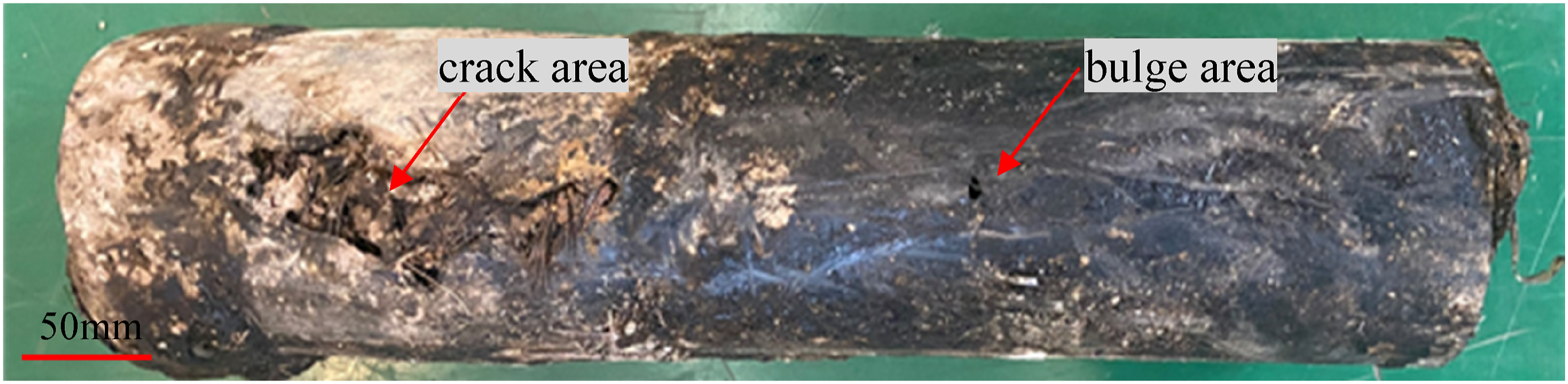
To determine the causes of SRTP pipe cracking failure, a series of experiments were conducted and a comprehensive analysis of the cause of fracture was carried out. The specific test measures for SRTP pipe failure analysis are as follows, the density of the lining layer in the SRTP pipe was test using ET-120SL density meter. TIME5410 Shore D hardness tester was used to test the hardness of the lining layer. The vicat softening temperature (VST) of the lining layer was tested with a VST tester (XRD-300DL, Chengde Jinjian Testing Instrument Co., Ltd, China). The degree of crosslinking of the inner liner was tested using a condenser tube, a 1000 mL three-neck round bottom flask, an electric heating sleeve, an analytical balance, and a copper mesh (125 ± 25 μm) with xylene. The attenuated total reflection spectroscopy (FTIR) was used to analysis the characteristic functional groups of the lining layer in the SRTP pipe using a Nicolet is50 Spectrometer (Thermo Fisher, USA). The thermal oxidation and degradation properties of the lining layer were studied using differential scanning calorimetry (DSC) (TA AQ200, USA) in nitrogen gas with 5∼10 mg samples were tested at room temperature and humidity of about 50%, heating rate was 10°C/ min and the range was 20∼300°C. Thermal analysis of the lining layer was carried out on a thermogravimetric analyzer (TGA) (METTLER TOLEDO TGA2 409C, Switzerland) in nitrogen gas with 5∼10 mg samples were tested at room temperature and humidity of about 50 %, heating rate was 10°C/ min and the range was 20∼650°C. The tensile strength and elongation of the lining layer were measured using a AGS-X10 KN Shimadzu ultra-large stroke testing machine. The tensile spline refers to the requirements of type I tensile spline in GB / T 8804.3-2003, and the wall thickness is about 5 mm ∼ 6 mm. The impact strength of the lining layer was tested using a XJJD simply supported beam impact testing machine. The impact test spline reference GB / T 1043.1 requirements in type I requirements, type A notch. The crack morphology of the lining layer of the failed pipe were systematically observed using an optical microscope (OM, smart zoom 5 optical digital microscope, Zeiss, Germany). The steel wire at the failure site was analyzed by scanning electron microscopy (SEM) and energy dispersive spectroscopy (EDS) (Gemini360 electronic scanning microscope produced by Zeiss, Germany).
Results and analysis
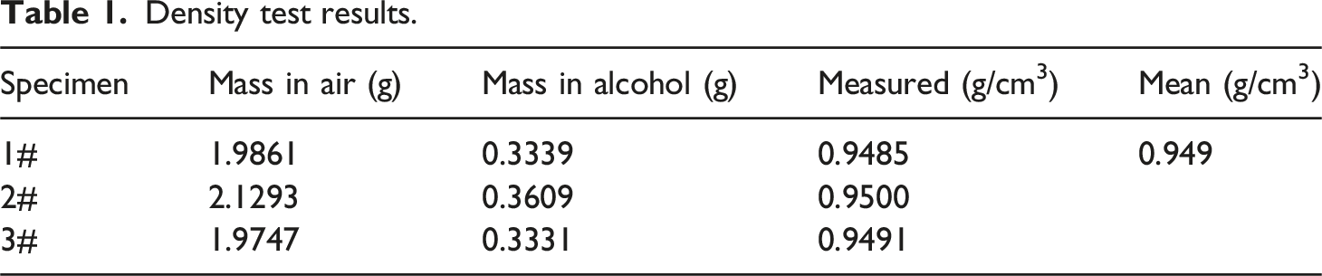
Density of the Lining Liner
Density test results.
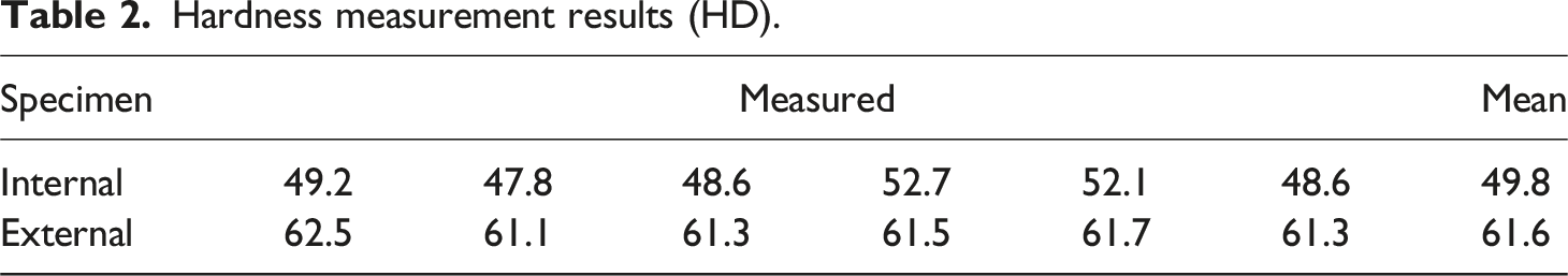
Hardness of the lining liner
Hardness measurement results (HD).
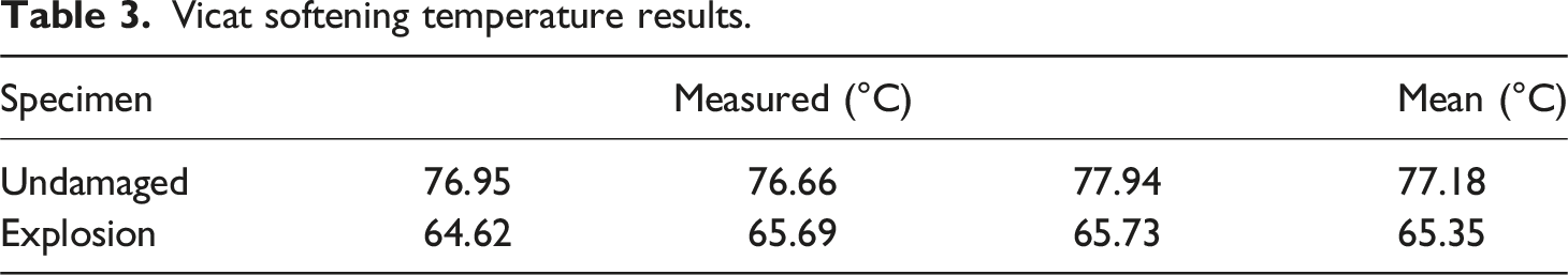
Vicat softening temperature of the lining liner
Vicat softening temperature results.
Deformation changing with temperature curve.
Crosslinking degree of the lining liner
Following the infrared analysis, which identified the lining resin of the SRTP as polyethylene to further clarify whether it is ordinary HDPE or cross-linked polyethylene (PEX), a crosslinking degree test was conducted using the xylene extraction method, as shown in Figure 3. The results are displayed in Table 4, indicate an average crosslinking degree of 72.54% for the inner lining layer, confirming the material to be PEX. Crosslinking degree test process. Crosslinking degree results (%).
Infrared Spectrum of the Lining Liner
Infrared spectroscopy was used to further analyze the structure and composition of the inner lining layer of SRTP pipes. As shown in Figure 4, the cross-section of the inner lining layer is sampled in sequence from the inside out, labeled 1# through 6#. The infrared spectrum confirms that the lining material is polyethylene (PE), with typical absorption peak of polyethylene, suggesting no significant change in the chemical structure. An absorption peak appears at the range of 1000∼1250 cm−1, presumed to be that of the swelling medium. Among them, 1226 cm−1 and 1179 cm−1 are the absorption peaks of C-O-C asymmetric stretching vibration in ethers, and 1031 cm−1 is the absorption peak of C-O-C symmetric stretching vibration in ethers. The intensity of the irregular absorption peak gradually decreases along the pipe wall from the inside out, indicating that the content of swelling medium in the polyethylene matrix gradually decreases from the inside out. ATR-FTIR spectra of the liner lining layer.
Differential scanning calorimetry of the lining liner
Compare and analyze the thermal oxidation and degradation properties of SRTP resin using DSC. Specimen from both undamaged and explosion area of the lining liner were tested for melting point, melting enthalpy, as well as oxidation induction temperature (OIT), presented in Figure 5. The intact part has a melting point of 140.77°C, melting enthalpy of 112.9 J/g, and OIT of 251.41°C. The damaged part shows a melting point of 134.54°C, melting enthalpy of 96.33 J/g, and OIT of 248.42°C. The melting enthalpy of the lining in the failure part is lower than that in the intact part, indicating that the lining material in the failure part is more likely to swell or decompose under the action of oil and gas medium, which is the weaker part of the pipe body. DSC curves of undamaged and explosion area of the resin.
Thermogravimetry
TGA was performed on the internal, midst, and outside from the lining liner from the SRTP. As demonstrated in Figures 6 and 7, the first step of weight loss for the internal and midst layers occurs between 150°C and 450°C, which is likely due to the release of the oil and gas medium absorbed by the material due to swelling. This results in a difference in thermal weight loss between the internal and midst layers of the lining sample compared to the external layer. The thermal decomposition temperature for the internal lining layer is 460°C, while it is 470°C for the midst and external layers, indicating that the swelling effect lowers the thermal decomposition temperature of the material. The TG results of different parts of the lining liner. The TG results of different parts of the lining liner (local amplification).
Tensile Strength
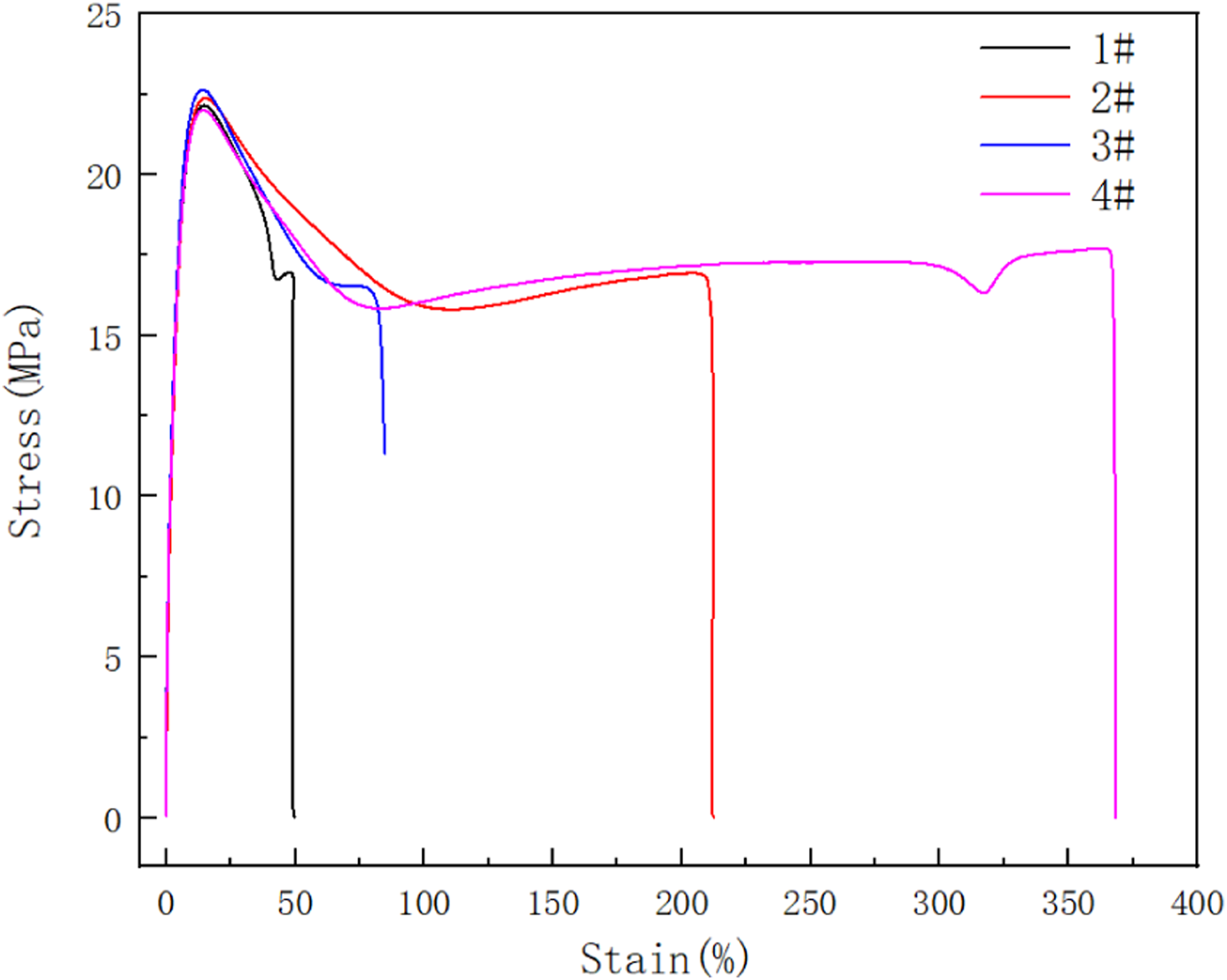
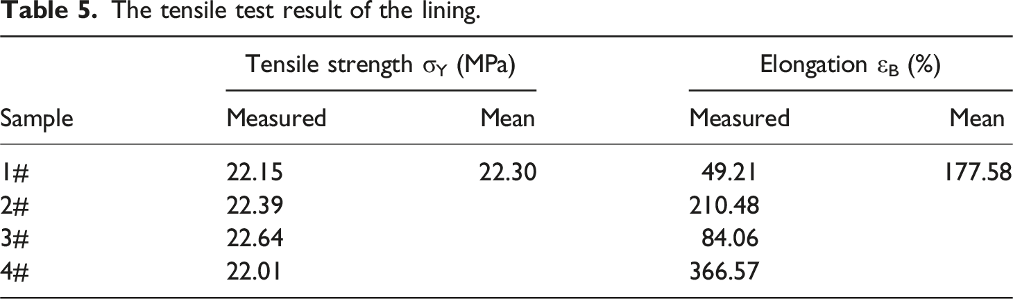
The tensile morphology of the lining is depicted in Figure 8, with the corresponding stress-strain curves shown in Figure 9. Test results presented in Table 5 show that the yield strength of the lining layer is relatively stable, whereas the elongation at break varies widely. The tensile morphology of the lining. Stress-strain curves of the lining liner. The tensile test result of the lining.
Impact Strength
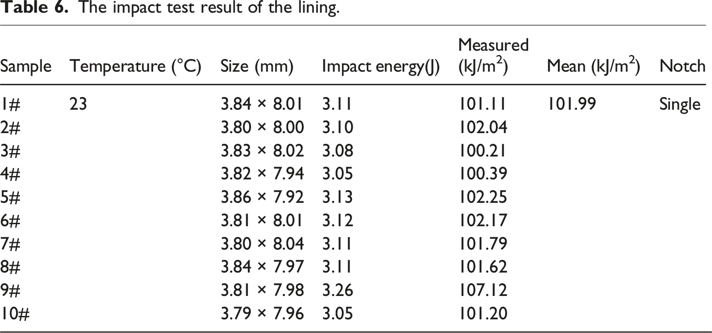
The impact test result of the lining.
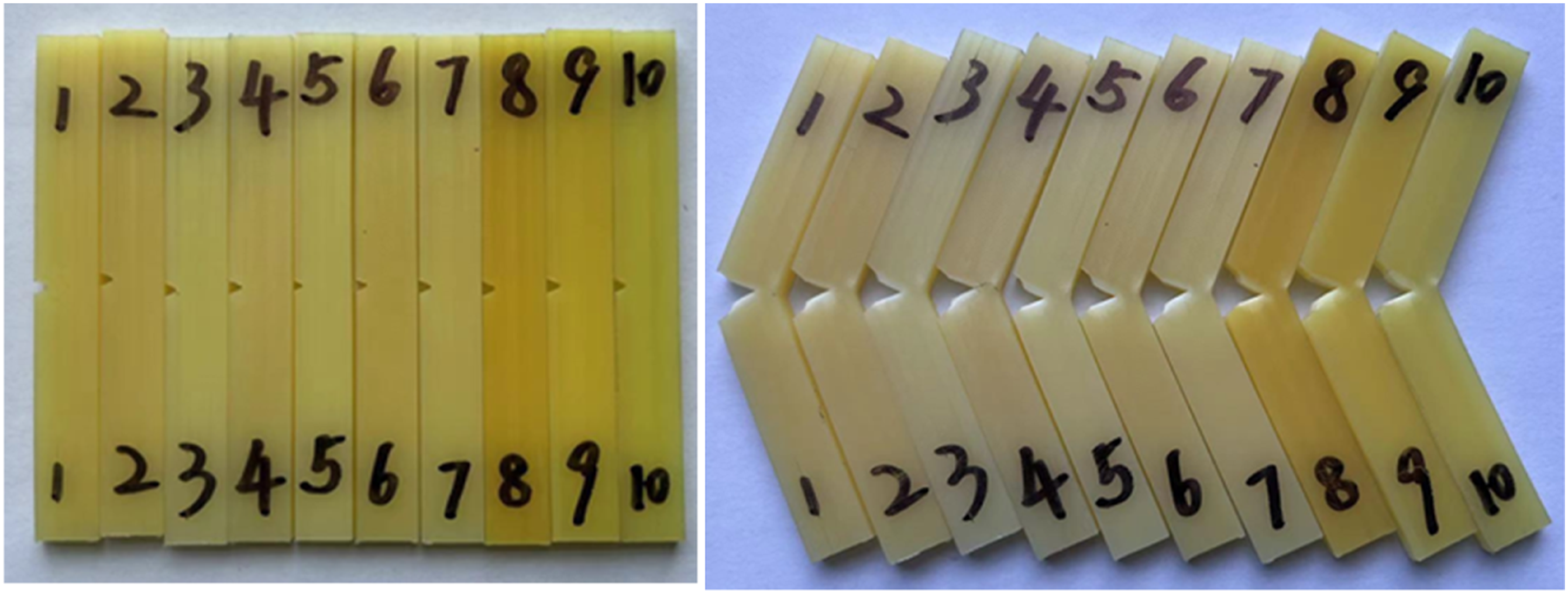
The impact morphology of the lining.
Morphology Analysis
As depicted in Figure 11, dissect the failed pipe section and remove the steel wire reinforcement layer and inner lining layer. The outer layer, reinforced layer, and inner layer of the failed pipe section all exhibit cracking. On the other hand, there has a bulge rupture of approximately 15 mm at the outer layer near the failure site. The corresponding surface of the reinforced layer is covered with a significant amount of crude oil, yet the structure of both the reinforced layer and the inner lining layer remains intact. Appearance morphology of failed pipe section after cutting open.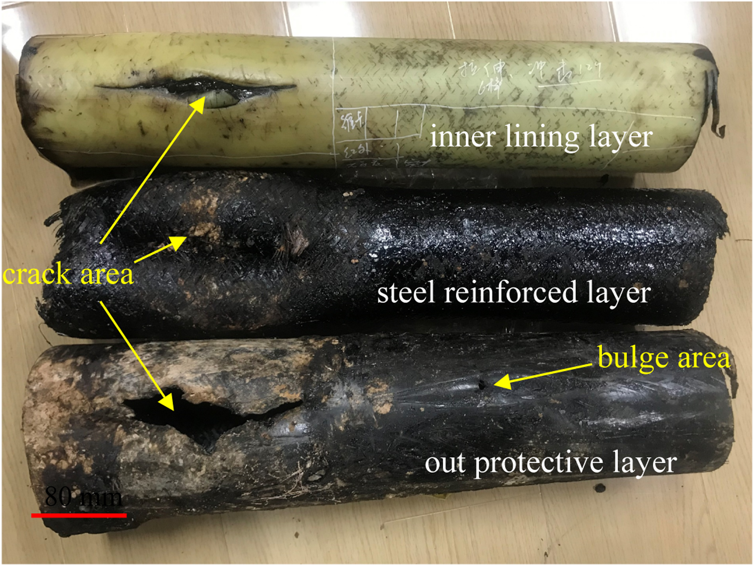
The macroscopic morphology of the inner and outer surfaces of the inner lining layer of the failed pipe section is shown in Figure 12. The outside of the lining layer has numerous strangulation marks due to the reinforcement. The inside appears darker compared to the outer surface, affected by the swelling from the oil and gas medium. In the failure region, the middle lining layer of the inner lining is ruptured by creep bulge, while the ends exhibit brittle cracking. Macroscopic morphology of lining in failed pipe.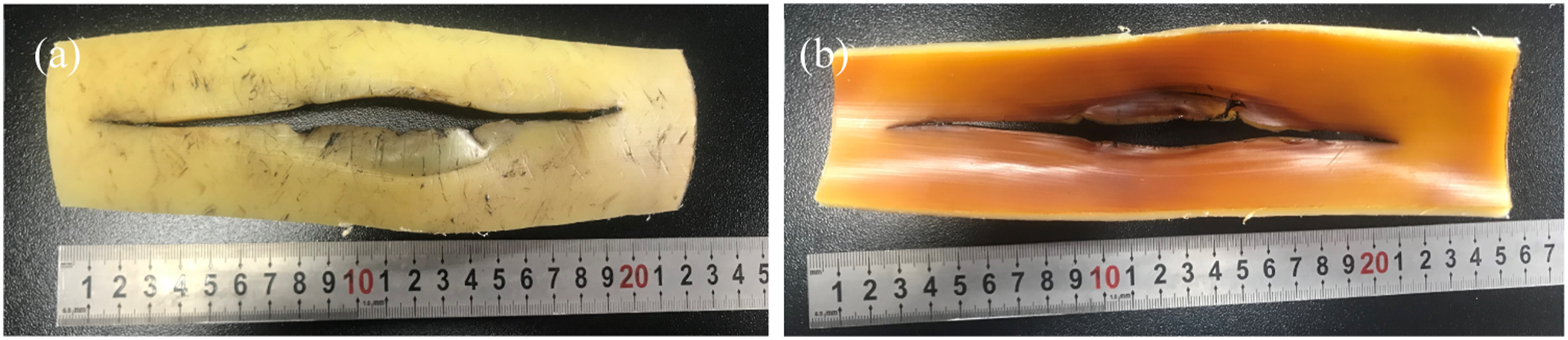
Figure 13 presents the outside morphology of the liner at the failure site, where numerous scars and scratches are evident near the fracture, caused by the reinforcing steel wire. Figures 13(a) and (b) show that bulge and thinning occur at the failure part of the lining layer. Figure 13(c) displays the inner surface morphology of the crack end at the failure site, where the surface is brown and the fracture is flat, indicative of brittle cracking characteristics. As seen in Figure 13(d), the cross-section of the pipe section changes color significantly due to oil swelling, measuring approximately 4.4 mm from the inside to the outside. Micro-morphology of the inner liner of the failed pipe.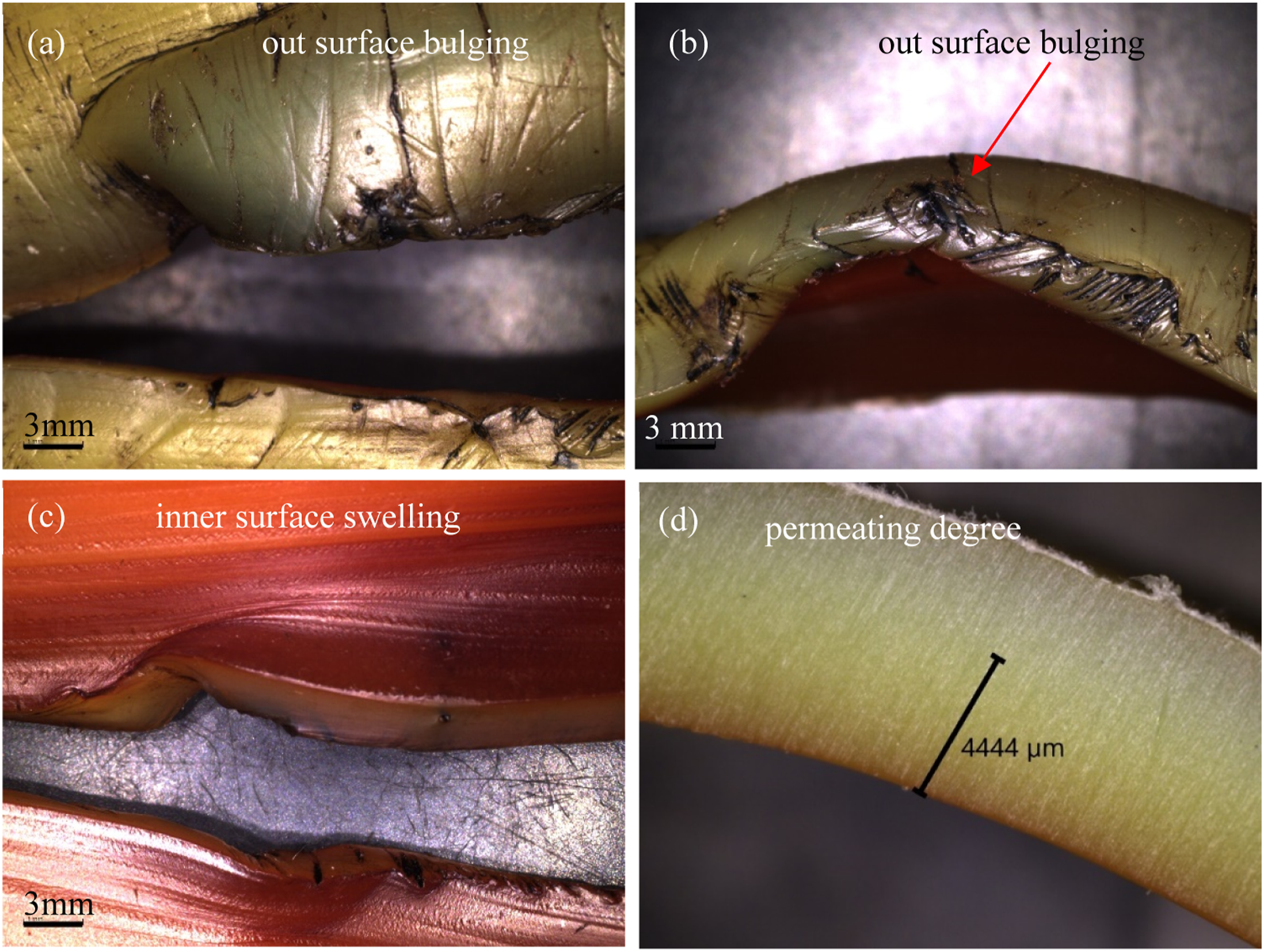
Electron microscope analysis
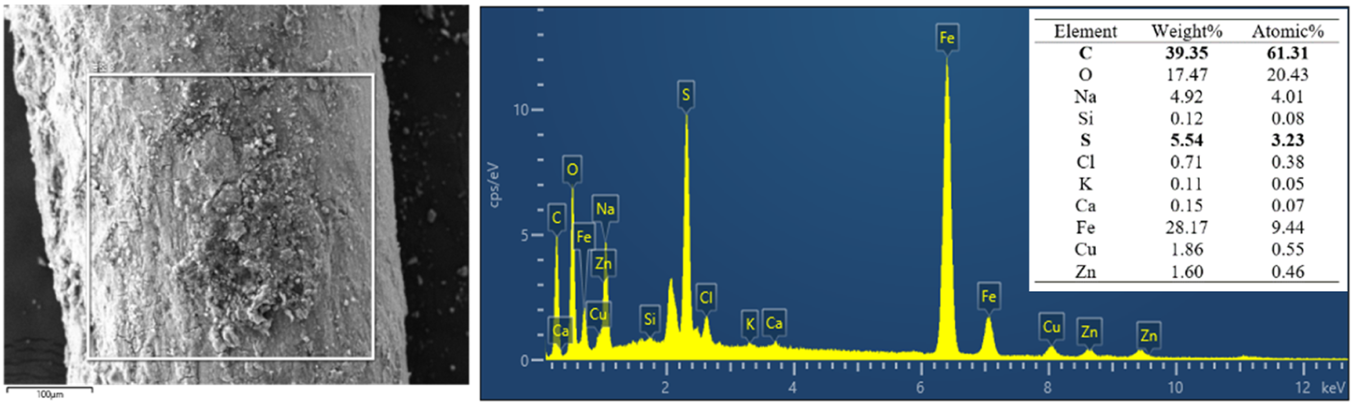
Figure 14 is the electron microscope morphology of the reinforced steel wire at the failure site. In Figure 14(c) and (d), a large amount of loose corrosion products can be observed adhering to the surface of the steel wire. The corrosion products are honeycomb-like, typical carbon dioxide and hydrogen sulfide corrosion morphology. In Figure 15, EDS was conducted on the corrosion products, a large amount of C, O, and S elements were found in the corrosion products, and direct evidence of the involvement of carbon dioxide and hydrogen sulfide in steel wire corrosion was found, which is consistent with the presence of a large amount of carbon dioxide and hydrogen sulfide in the transport medium (containing 9.71% CO2 and 12,539.76 mg/m3 H2S). The CO2 and H2S gas penetrates into reinforcement layer through the inner lining layer, and the corrosion reaction occurs with the steel wire, which leads to the decrease of the bearing capacity of the reinforced steel wire, and the bulge thinning of the inner lining layer until the cracking failure. The SEM of the reinforced steel wire at failure site. EDS result of the reinforced steel wire at failure site.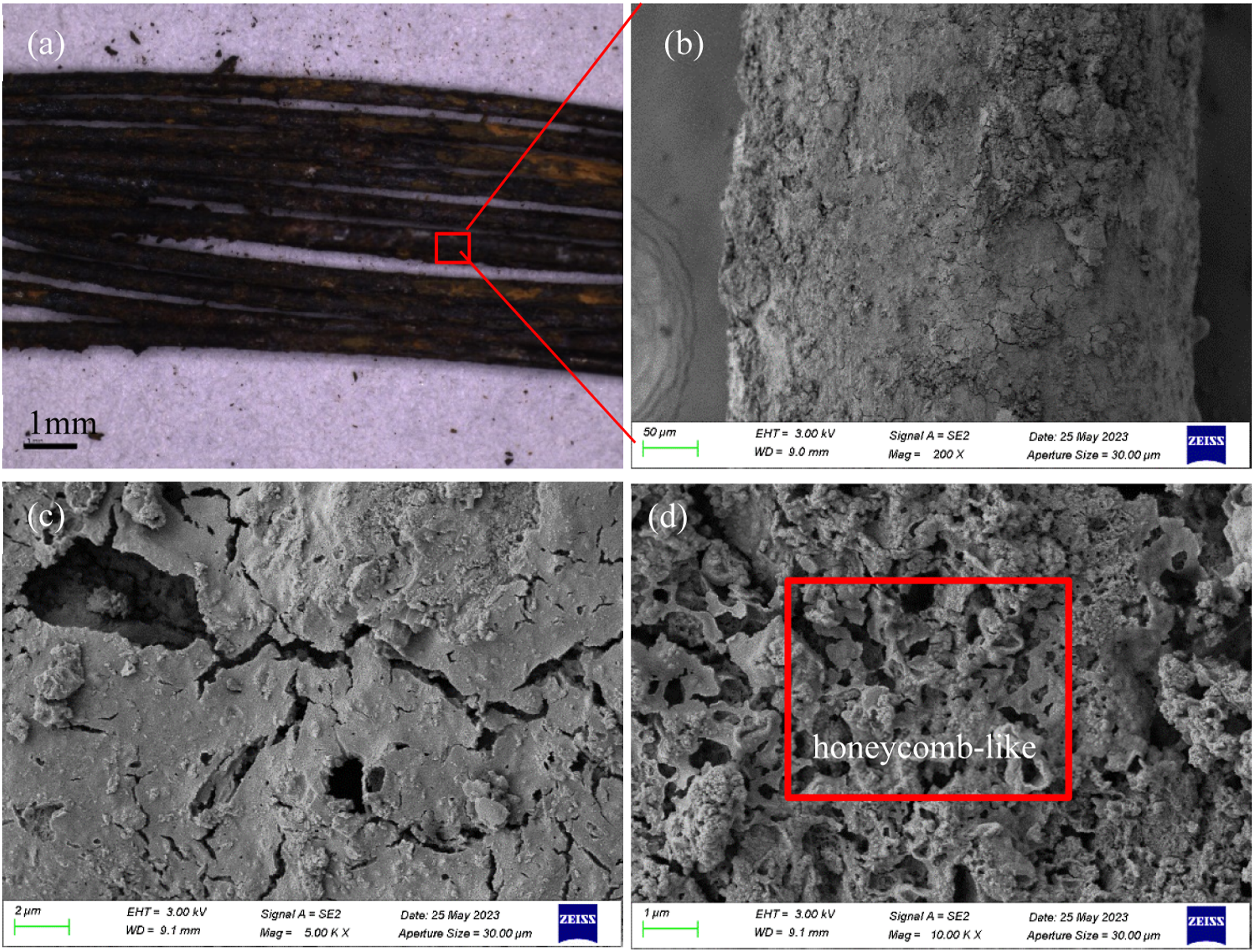
Discussion
Material analysis
The liner density of the SRTP pipe complies with the GB/T 15,558.1-2015 standard. Infrared spectroscopy and crosslinking degree tests confirm that the lining material is PEX. Morphology analysis indicates that the inner surface of the lining layer has undergone a swelling effect due to the prolonged exposure to oil. Specifically, the shore hardness of the liner was approximately 14% lower than that of the outside, the VST (B50) was around 15% lower, and the melting point, oxidation induction temperature, and thermal weight loss temperature were also decrease than those of the outer surface. Mechanical testing reveals the tensile strength and impact resistance of the lining material remain stable, while the elongation at break is quite variable, with an average of 177.58%, which falls short of the GB/T 15,558.1-2015 standard requirement (≥350%). Corrosion is evident on the reinforced steel wire at the failure site, with a substantial amount of carbon dioxide and sulphur-containing corrosion products present. The corrosion of steel wire reinforcement can lead to a decrease in the pressure bearing capacity of composite pipes.
Failure cause analysis
According to Figure 16, the daily production report of the pipe was analyzed for approximately 1 month before and after the failure of the SRTP pipe. The operating pressure ranges from 1.5 to 2.2 MPa, and the service temperature varies between 69.4 and 77.7°C, exceeding the maximum allowable operating temperature of cross-linked polyethylene does not exceed 75°C. The pipeline failed on January 5, 2023. Production data indicate that both temperature and pressure were at elevated levels (temperature at 75.7°C, pressure at 2.11 MPa) during this period, which likely contributed to the increased risk of failure. Operating temperature and pressure before and after failure of SRTP pipe.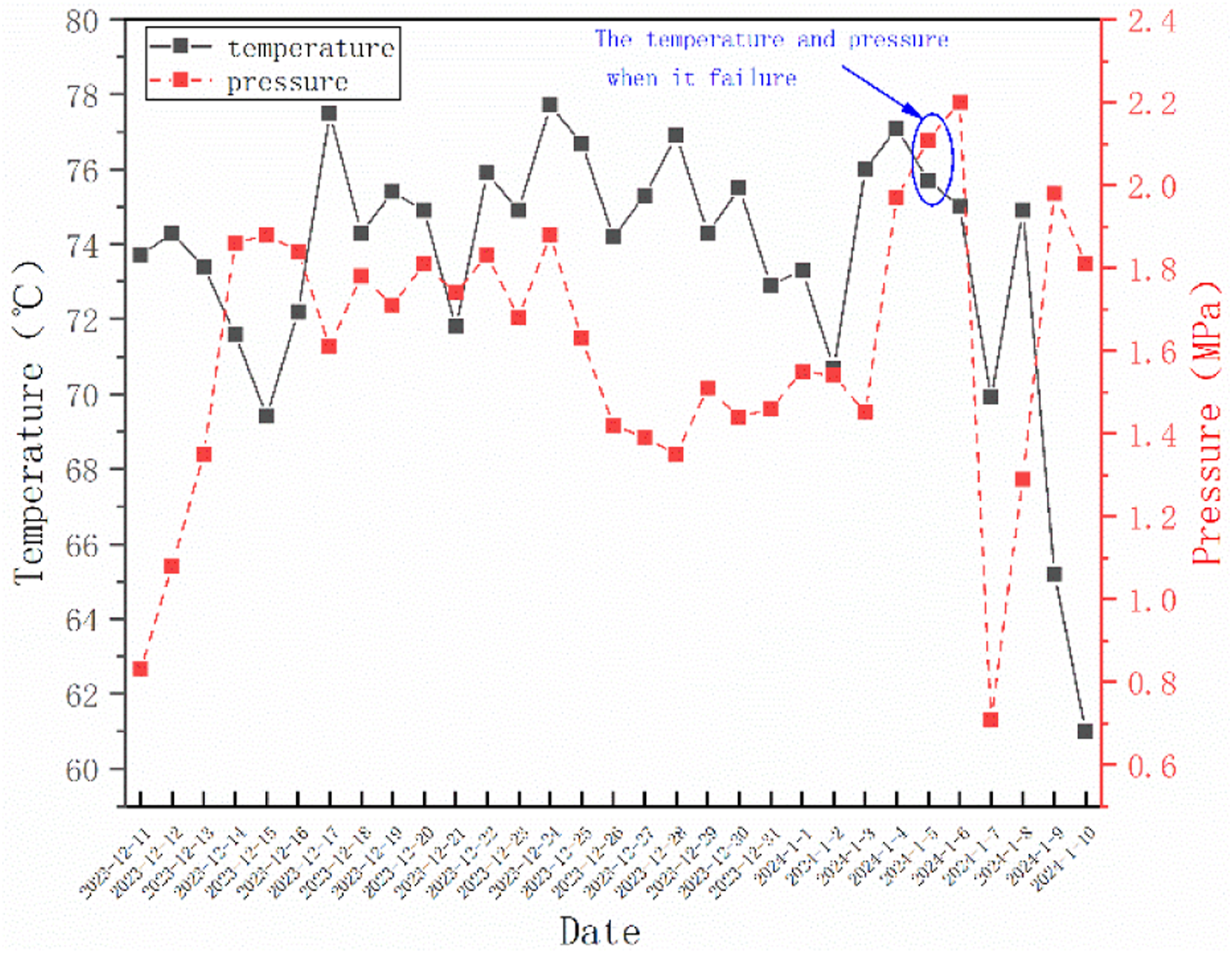
Morphology analysis reveals numerous strangulation marks on the outside of the inner lining, resulting from the reinforcing steel wire. The inner surface appears darker and more brownish than the outer surface, affected by the swelling impact. The oil medium is observed to have penetrated approximately 4.4 mm, with the outer protective layer exhibiting signs of bulging and thinning. The analysis of the lining material suggests that the infiltration and swelling effect of the oil medium softens the inner surface, reducing its heat, oxidation resistance, and degradation capability, and decreasing the thermal decomposition temperature of the material to varying degrees. Therefore, the presumed cause of failure for the SRTP pipe as follows: under the swelling effect of the oil medium and the infiltration of CO2 and H2S gas, oil and acidic gases enter the interlayer of the composite pipe, accumulate in the annulus, continuously corrode the reinforced steel wire, gradually diminish its load-bearing capacity, and ultimately lead to the pipe body’s inability to withstand pressure, resulting in burst.
Conclusions and preventive actions
1. The lining material of the SRTP is PEX, the lining layer of the failed tube sample exhibits a significant swelling effect, which impairs its performance. Operations at high temperatures (>75°C) will hasten this degradation. 2. Swelling of the oil medium and the permeation of CO2 and H2S gases causes the oil and acid gases to penetrate the interlayer and accumulate in the interlayer. This process continuously corrodes the reinforcing steel wire, progressively diminishing its bearing capacity and leading to the pipe body’s inability to sustain adequate pressure, ultimately resulting in burst failure. 3. The failed part of the pipe body is located only one meter from the joint. It is recommended that when SRTP fails near a joint, the joint adjacent to the failed section of the pipe should also be sampled and analyzed. 4. Non-metallic pipes should be selected based on service conditions to ensure a match between the material used in the pipeline and the original design specifications.
Footnotes
Declaration of conflicting interests
The author(s) declared no potential conflicts of interest with respect to the research, authorship, and/or publication of this article.
Funding
The author(s) disclosed receipt of the following financial support for the research, authorship, and/or publication of this article: This work was supported by the National Natural Science Foundation of China; 52274069.