
Abstract
Accumulated snow on roads presents a dual risk of accidents and financial losses. Conventional de-icing methods, which rely on chemicals, salt, and heavy machinery, are unsustainable and detrimental to both the environment and infrastructure. Furthermore, they demand significant labor and pose hazards in densely populated areas. In response, heated pavement systems such as hydronic and electrically conductive concrete (ECON) have gained traction for mitigating snow accumulation on roads. However, the use of carbon fiber and carbon black in ECON raises costs and depletes valuable resources. This research introduces an inventive and sustainable approach to address snow accumulation on rigid pavements during winter. The proposed method utilizes waste rubber tires (WRT) as heating pads for pavements. The steel wires within these tires generate heat when an electric current is applied. The study validates this method by embedding WRT across the rigid pavement, creating an electric circuit connected to a power source. The rubber tire pads demonstrated high efficiency in conducting electricity, significantly increasing temperatures with a 6 V supply. The tire rubber pads reached up to 46.3°C and 60°C using different electric circuit designs, compared with the ambient temperature of 22°C–23°C. Embedded in concrete, these pads raised surface temperatures to as high as 52°C, effectively melting snow, ice cubes, and crushed ice within 1 h. This method provides an environmentally friendly and sustainable solution. This research unveils a groundbreaking strategy for de-icing snow on rigid pavements, offering a sustainable substitute for traditional de-icing procedures and addressing resource depletion.
Keywords
Throughout history, advancements in transportation infrastructure have spurred rapid urbanization, making transportation safety a paramount concern. Weather conditions, such as rain, ice, or snow, significantly affect accident rates. Based on statistical data, approximately 10%–15% of all road accidents are attributed to adverse road conditions and inclement weather ( 1 ). This significant percentage results in numerous human injuries, fatalities, and substantial property damage annually. It is important to note that ice accumulation on road surfaces does not solely affect vehicles; it also poses a hazard on sidewalks, leading to personal injuries caused by slips and falls ( 1 ).
Clearing roads of snow and ice is crucial in colder regions to prevent infrastructure deterioration and concrete pavement damage. Traditional de-icing methods, such as chemical sprays and large snow removal machinery, have drawbacks including ineffectiveness in exceptionally low temperatures, environmental harm through potential water pollution, and higher labor costs ( 1 ). Chemical compounds and fine aggregates are the primary agents used for de-icing and anti-icing in the majority of winter maintenance procedures for highways. While sodium chloride is often considered the most cost-effective option, its use can lead to the corrosion of steel reinforcement, pavement erosion, and environmental pollution ( 2 ). Additionally, the use of mechanical equipment may result in external damage and increased maintenance costs ( 3 ). These techniques are time-consuming, labor-intensive, and environmentally detrimental, as de-icing chemicals can harm soil, surface runoff, and groundwater, thereby affecting the entire ecological system ( 4 , 5 ).
Several innovative techniques have emerged to enhance the removal of ice and snow from surfaces, serving as alternatives to conventional methods. Extensive research endeavors have been dedicated to devising cleaner and more sustainable approaches to effectively address ice and snow accumulation on pavements. The heated pavement system (HPS) has emerged as an alternative, encompassing the hydronic heating pavement system (HHPS), electrically heated pavement system (EHPS), and electrically conductive concrete (ECON) systems ( 2 ). While paving materials have various attributes that are necessities for structural and non-structural applications, leveraging their electrical and thermal properties holds immense potential for long-term pavement solutions ( 3 ). The hydronic method works by heating water to melt ice and snow—heated fluid is circulated through pipes buried in pavement structures. The cooled fluid is heated each time it passes through the heat source ( 6 ). Geothermal waters, boilers, and heat exchangers are all examples of heat sources. In areas where geothermal potential is high, geothermal water is thought to be highly effective ( 7 ). The drawbacks of hydronic systems are that they are complex to create, require a large investment in installation costs, and are difficult to repair if a fluid leak occurs ( 7 ). Recently, HHPS was erected on the aprons of the Greater Binghamton Airport in Binghamton, New York State, U.S. The total area of the project was 3,200 ft2 (297 m2) at a cost of $1,600,000 ( 8 ). Gardermoen International Airport in Norway developed HHPS by using aquifer thermal energy storage to heat and cool the aircraft parking space, which is 7,450 ft2 (700 m2) ( 9 ). Another technique for heating the pavement involves converting electric energy into heat energy using different mediums. Electric heating cables, in particular, have demonstrated significant efficiency in this application. Recent research, as cited in Arabzadeh et al., highlights the efficacy of carbon-fiber heating cables (CFHC) in snow- and ice-melting applications on roads ( 10 ). The study conducted tensile and compressive tests to assess the mechanical properties of CFHC, revealing that it meets the necessary strength requirements for pavement applications. Moreover, CFHC demonstrated the ability to withstand multiple heating and cooling cycles without significant degradation, indicating its suitability for long-term use. Embedding CFHC in concrete does not compromise the pavement’s strength, ensuring both durability and effectiveness in real-world conditions. Among de-icing techniques, the ECON pavement system may be regarded as the most effective way for removing snow off roads, since it is a strategy that is inexpensive, efficient, ecologically friendly, and sustainable. This is a specialized type of HPS with a top concrete layer produced by adding electrically conductive material, such as carbon fibers and steel shavings, into the concrete mixture ( 4 , 12–15). These systems not only improve the accessibility of transportation infrastructure, but also eliminate the need for enormous amounts of chemicals and vehicles powered by fossil fuels to remove snow and ice.
Researchers have been exploring more sustainable approaches to waste management and recycling. Among the most effective techniques are recycling and reusing materials. With the rising number of vehicles, substantial quantities of waste tires accumulate yearly, posing an ecological challenge. Incorporating waste rubber tires (WRT) into construction, especially in pavement systems, could reduce landfill space and diminish storage duration, thus curbing environmental hazards associated with tire waste. Notably, the pavement sector has emerged as a beacon of progress, as it involves the recycling of diverse waste types for a range of pavement applications, encompassing rigid pavement, asphalt concrete, and bitumen. Numerous studies have been undertaken to explore the utilization of tire rubber in pavement applications and civil engineering in general ( 16 ). Among these studies, Bulei et al. discussed the components resulting from the crushing of old tires into powders, which are used in rubber-containing street furniture or building materials, highlighting the potential for these materials to be incorporated into various construction applications ( 17 ). Arulrajah et al. conducted an experimental investigation to understand the compression behavior of concrete when natural aggregates are partially replaced with recycled tire rubber in varying amounts, ranging from 10% to 50% by volume ( 18 ). This study aimed to evaluate the feasibility and impact of using recycled tire rubber as a sustainable alternative in concrete mixtures. Girskas and Nagrockienė performed several experiments to assess the compressive strength, water absorption, and ultrasonic pulse velocity of concrete specimens modified with rubber crumb ( 19 ). Their work focused on the mechanical properties and durability of rubberized concrete. Li et al. reviewed and analyzed significant achievements in crumb rubber concrete (CRC) over the past 5 years, examining aspects such as fresh concrete qualities, mechanical properties, and overall durability ( 20 ). This comprehensive review provided insights into the advancements and ongoing research in the field of CRC. Similarly, Thomas and Chandra Gupta summarized findings from their experimental investigation into using recycled tire rubber as a partial replacement for natural fine aggregate in high-strength cement concrete ( 21 ). Their study emphasized the mechanical performance and potential benefits of incorporating recycled rubber into concrete mixes. In further research, Guo et al. aimed to enhance the performance of rubber concrete through various surface treatments and coating techniques ( 22 ). This study explored different methods to improve the bonding and mechanical properties of rubber-cement composites. Mohammadi established a relationship between the strength of rubberized concrete and key parameters, such as the water-cement ratio, age of the concrete, and rubber content, based on extensive experimental data ( 23 ). Hossain et al. evaluated the feasibility of using large rubber blocks from crushed tires as aggregates in cold mixes for road construction ( 24 ). Their study aimed to produce block rubberized asphalt concrete mixtures for small-scale road construction projects. Mohammed et al. provided a review of recent investigations into the characteristics of rubbercrete, focusing on both fresh and hardened properties, as well as potential applications ( 25 ). Lastly, Radwan and Raheem presented a sustainable approach for de-icing rigid pavements using WRT as heating elements ( 26 ). Their research demonstrated the feasibility of using steel wire meshes embedded in rubber tires to generate heat, providing an effective, eco-friendly alternative to traditional de-icing methods.
This study aims to utilize WRT to develop an efficient and sustainable construction method for EHPS. The primary goals are to address snow accumulation on rigid pavements, minimize raw material usage, and reduce environmental impact. By leveraging the electrical and thermal properties of recycled rubber, this research seeks to enhance pavement safety and durability during winter conditions, offering a more sustainable solution to traditional snow removal methods.
Methodology
This research was inspired by the concept of invisible thermally conductive paint employed for defrosting and defogging laminated car windshield glass (see Figure 1). Drawing inspiration from this technology, the study developed an innovative methodology for de-icing pavements using electrically conductive stripes. This approach is considered a more sustainable construction option than most of the current snow removal techniques and HPS for effectively and safely eliminating ice and snow from pavements, because of its low costs, minimal pavement damage, and environmental friendliness.
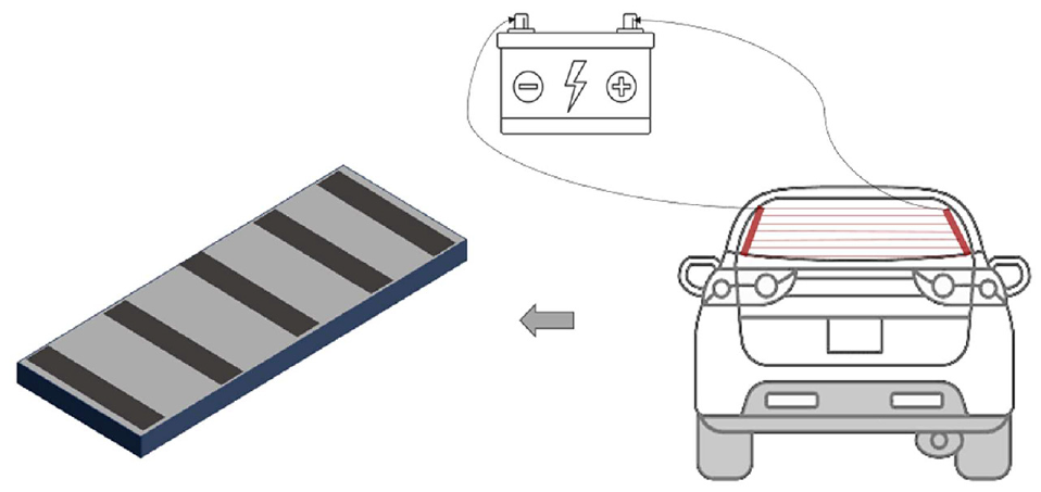
Concept of the proposed construction method for an electrically conductive pavement.
The rubber tires are composed of approximately 10%–12% steel wires, produced from high-carbon steel which is highly electrically conductive. This study aims to bridge a gap in previous research on snow melting, which predominantly focused on efficiency, overlooking critical aspects such as cost, environmental impact, and sustainability. The objective is to propose a new, environmentally friendly, and cost-effective method for snow melting. This method centers around the utilization of WRT in lieu of conventional materials such as carbon black and carbon fiber. This shift would not only diminish the annual tire waste and reduce landfill storage time but also alleviate associated environmental concerns.
The study explores the feasibility of utilizing a mesh of steel wires embedded in WRT as an electrical and heat-conducting element to generate sufficient heat for snow melting on rigid pavements used in highways, bridges, and airport runways. The study’s objectives encompass resolving snow accumulation issues, curbing raw material consumption through sustainable sourcing, and proposing new applications for WRT within the construction industry. Figure 2 illustrates the system’s concept, drawing inspiration from the valuable steel wire mesh embedded in rubber tires.
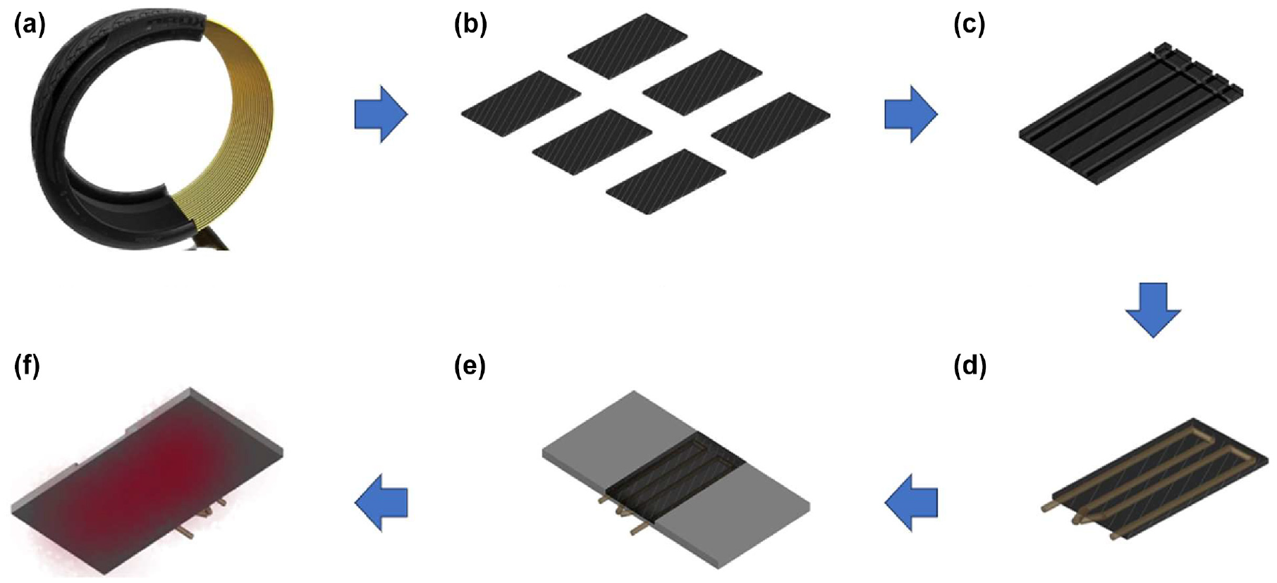
Illustration of the research methodology: (a) a waste rubber tire, (b) rectangular pieces, (c) grooved rectangular piece, (d) installed electrical circuit, (e) heated concrete sample, and (f) combined concrete sample.
The study’s approach unfolds in three stages. The initial stage entails harnessing the electrically conductive properties of the steel wire mesh embedded in the rubber pads. Since the embedment of the wire mesh forms an electric circuit, it can produce heat when connected to a power source. Consequently, the rubber sample functions as a heat source. The second stage involves embedding the rubber sample (the heat source) within the concrete (the rigid pavement). Finally, the third stage focuses on evaluating the performance of the new electrically conductive pavement (comprising the rubber sample and concrete) in effectively melting ice.
Figure 3 shows a schematic assumption for real-world application, providing a conceptual framework for how the system could be implemented in practical scenarios. The figure depicts a layered arrangement, with the thick concrete layer serving as the base. The electrically conductive WRT pads are strategically placed on top of this thick concrete layer. Above these pads lies a thin concrete layer, which encases the rubber pads within the overall slab structure. This setup is designed to ensure that the rubber pads are well-integrated and can effectively contribute to the uniform heating of the concrete surface.
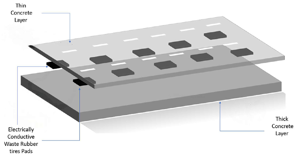
Different layers of the proposed electrically conductive pavement.
Proposed EHPS Design
Rubber Samples Preparation
A rubber tire sample was obtained and subsequently cut into rectangular pads, as illustrated in Figure 4. These rubber pads were then meticulously cleaned, brushed, and marked with the necessary dimensions, as demonstrated in Figure 4. Specifically, only the tread portion of the tire was utilized, as it contains the majority of the steel wire mesh, whereas the sides do not. Notably, the width of the tire tread measures approximately 15 cm, as illustrated in Figure 4, d and e . To maximize material, use and ensure uniformity, it was divided into three segments, each with a width of 5 cm. This discretion ensures each pad has sufficient steel wire mesh for effective heat generation and uniform distribution.
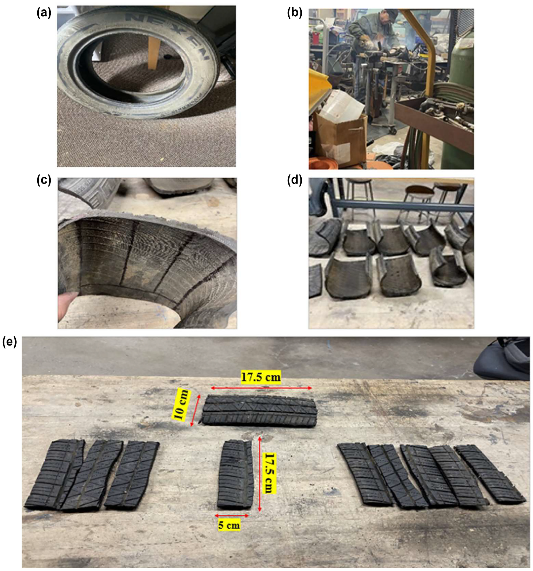
Processing of rubber pads: (a) a waste rubber tire, (b) cutting into eight equal pieces, (c) eight equal pieces, (d) marked to the desired dimensions and (e) desired dimensions.
Two distinct types of rubber pad were fabricated. The first variety, labeled the “exposed sample,” involved the complete removal of the top layer of rubber to access the underlying steel wire mesh. In contrast, the second category, termed the “grooved sample,” entailed the creation of parallel grooves to reach the wire mesh without necessitating the removal of the entire top layer. This approach proves to be more efficient and timesaving, as it eliminates the need for complete removal. Figure 5 provides a visual comparison between the exposed sample and the grooved sample.
Two distinct types of rubber pad: (a) exposed rubber sample and (b) grooved rubber sample.
Rubber Pad Steel Mesh
The steel cords found in tires are typically composed of high-tensile steel wire, which exhibits a notable strength-to-weight ratio, allowing it to endure the rigors of road conditions, rendering it an excellent choice for tire cord material. These steel cords are usually constructed from multiple strands of high-tensile steel wire that are intertwined to form a cable-like structure. Following this, the steel wire undergoes a zinc coating process to prevent corrosion and enhance adhesion to the surrounding rubber.
Building the Electric Circuit
To create an electric circuit using the rubber pads, two different types of conductor were employed to connect the rubber pad to the electrical source. These two types are bare copper wire and galvanized steel wire. Copper wire is renowned for its exceptional electrical conductivity, boasting an approximate electrical conductivity of 100% International Annealed Copper Standard (IACS). IACS is a measure used to compare the electrical conductivity of various materials with that of pure annealed copper, which is considered to have 100% conductivity on this scale. It is also characterized by low electrical resistance, which facilitates the efficient transmission of electrical energy. However, copper is relatively expensive, which has led to the utilization of galvanized steel wire in electrical circuit design. Galvanized steel wire offers cost-effectiveness and, although it has a lower thermal conductivity and higher electrical resistance compared with bare copper wire, it remains a suitable alternative.
It should also be noted that the electrical resistivity (ρ) of the tire-steel wire measures 2.55 × 10⁻⁷ Ω m, whereas the galvanized steel wire records a substantially higher value at 129.7 × 10⁻⁷ Ω m. This indicates a considerable difference, underscoring that the galvanized steel wire’s resistivity is significantly larger than that of the tire-steel wire.
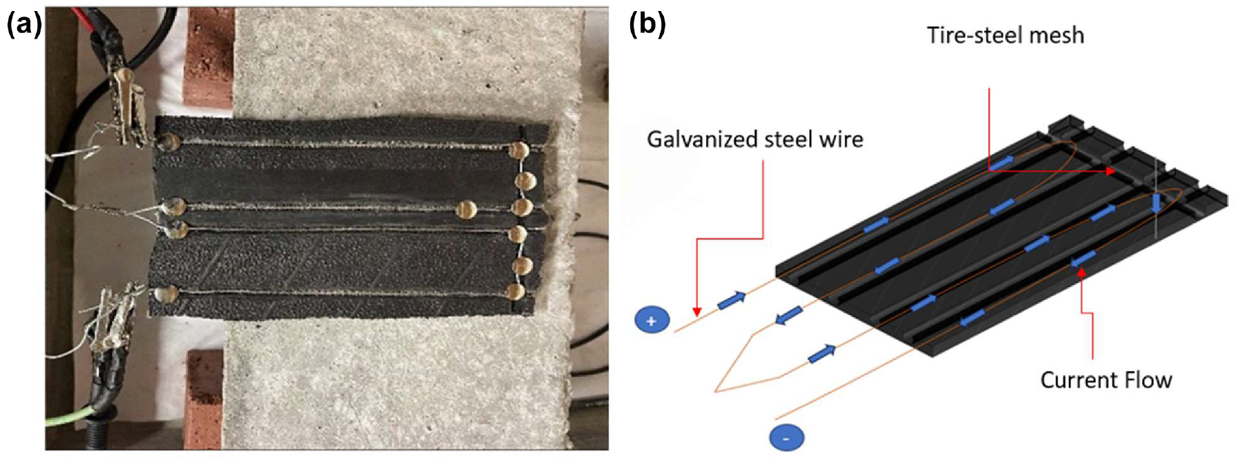
The proposed rigid EHPS design involves establishing an electrical circuit using either copper or galvanized steel wire to establish contact with the steel wire mesh within rubber samples, regardless of whether they are exposed or grooved. This leads to the flow of an electrical current through the steel cords encased in the rubber, resulting in the generation of sufficient heat. A key challenge was determining the extent to which the steel wire mesh within the rubber needed to be cleaned and revealed, as any residual rubber or imperfections along the cords could directly affect the current flow. Figure 6 illustrates various designs of electrical circuits. For instance, Figure 6a showcases a circuit employing two parallel copper wires, with metal pins ensuring proper contact with the steel cords within the rubber. Figure 6, b and c , present circuits designed based on the shape of the grooves, employing copper wire and galvanized steel wire, respectively. Finally, Figure 6d shows a grooved sample created in a U-shape, utilizing a galvanized steel wire to design the electric circuit. It is important to note that the electric circuit design was improved through experimentation with different wire types and connections. This was done to achieve a uniform heat distribution over both the front and back faces of the rubber sample, resulting in a gradual temperature increase.
Various electrical circuits designs using copper wire and galvanized steel wire for exposed and grooved rubber samples: (a) exposed using copper wire, (b) L-shape using copper wire, (c) L-shape using galvanized steel wire, and (d) U-shape using galvanized steel wire.
Rigid EHPS Samples
The preparation of concrete specimens, as depicted in Figure 7, commenced after confirming the rubber pads’ ability to generate sufficient heat. In accordance with the ACI 318 specifications, two concrete samples were created. While the concrete was still in its plastic state, the rubber pads were embedded into it. Sample 1 measured 20 cm in width and 30 cm in length, with the rubber sample placed in the center. In contrast, sample 2 had dimensions of 20 cm in width and 40 cm in length, incorporating two rubber samples positioned at consistent intervals of 5 cm from the edge and 10 cm from the center.
Different concrete electrically heated pavement system (EHPS) made with recycled rubber tire pads: (a) sample 1 of concrete EHPS with one rubber pad and (b) sample 2 of concrete EHPS with two rubber pads.
Experimentation Setup
The experimentation was conducted in two distinct phases. The primary phase focused on testing the four designs for the rubber pads (see Figure 6) individually to evaluate their capability to achieve elevated temperatures—when connected to a source of electricity—while guaranteeing uniform heat distribution across both the front and back surfaces of each pad. In the subsequent phase, the concrete samples were subjected to testing after the rubber pads were integrated into them. The goal was to monitor the temperature rise on the flat concrete surfaces of the EHPS.
Before initiating the measurement of the temperature rise for the four rubber pads shown in Figure 6, it was imperative to establish the resistance of the electrical circuit established in each pad. Figure 8 illustrates the use of a multimeter for measuring the resistance, a critical step in validating the efficacy of the designed circuit and evaluating conductivity. The resistance values ranged from 0.8–1 Ω. Subsequently, each pad was annotated with colored shapes, denoting precise locations where temperature readings would be taken, as depicted in Figure 9. The blue triangles indicate the top strip, the orange circles indicate the middle strip, and the green diamonds indicate the bottom strip.
Testing the electrical conductivity and the resistance of the four rubber samples: (a) exposed using copper wire, (b) L-shape using copper wire, (c) L-shape using galvanized steel wire, and (d) U-shape using galvanized steel wire.
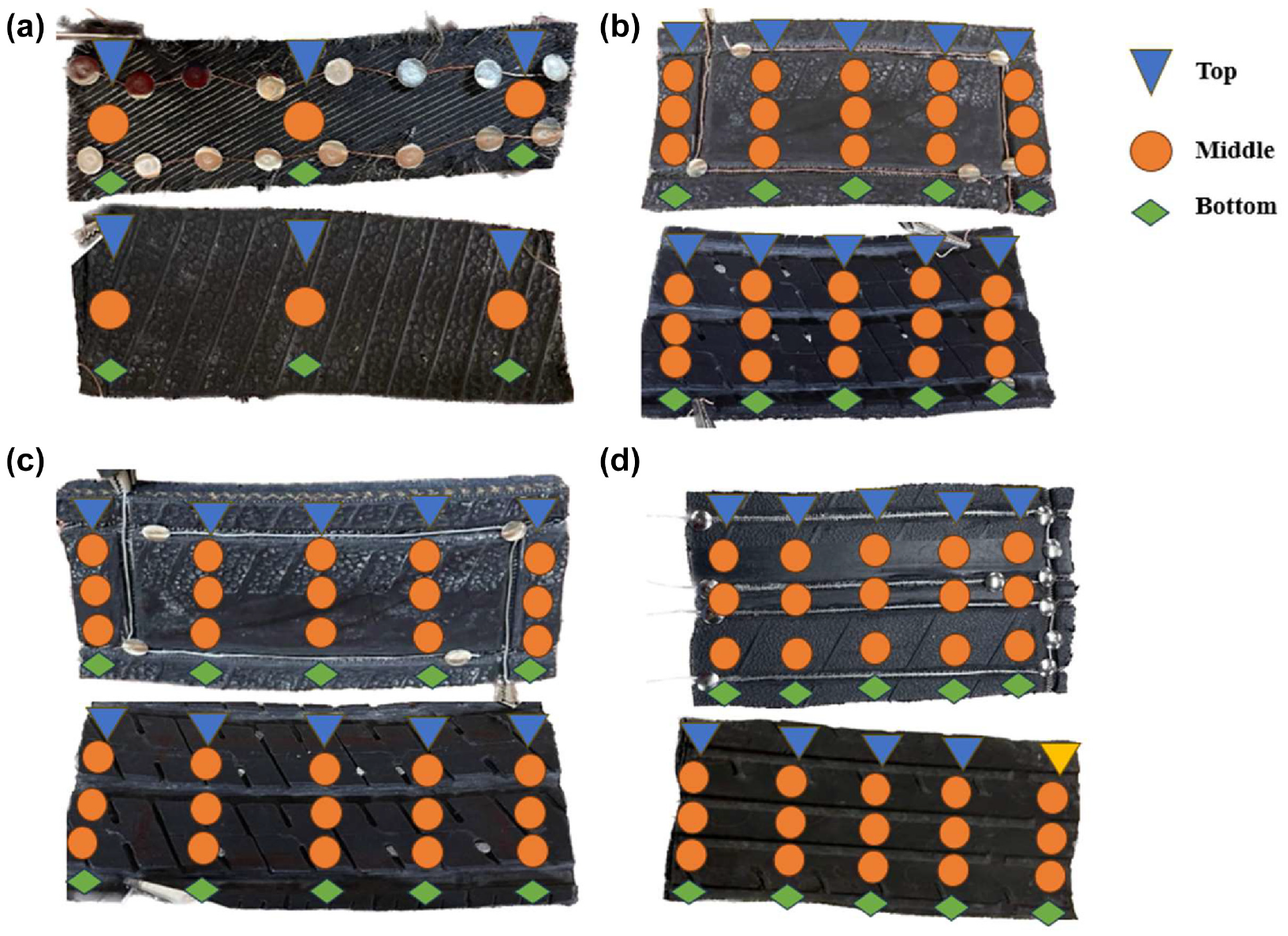
Measuring and recording the rise in temperature for each rubber pad on both sides: (a) exposed using copper wire front and back faces, (b) L-shape using copper wire front and back faces, (c) L-shape using galvanized steel wire front and back faces, and (d) U-shape using galvanized steel wire front and back faces.
The selection of these points was informed by the need to: capture heat distribution (measure temperatures at multiple locations to understand how heat spreads from the heating pads through the concrete), identify hot spots (determine if there are any areas with significantly higher temperatures, indicating potential hotspots that could affect the pavement’s performance and durability), and ensure uniform heating (verify that the heating system provides consistent temperature increases across the entire surface, which is essential for effective de-icing).
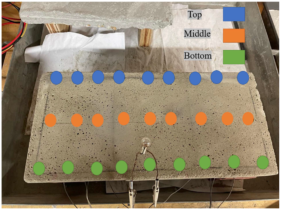
The two concrete samples (single- and double-padded) underwent a similar preparation process, involving the marking of colored circles. Temperature rise was monitored across the entire concrete surface, considering that this side would be exposed to vehicles, while the rubber-faced side was positioned facing downward to protect it from possible damage caused by the exerted loads on the surface of the pavement. Both concrete EHPS samples were equipped with an LED light bulb connected to the circuits, serving as an indicator of current flow. The upper edge of the concrete sample was marked with blue circles, the middle strip with orange circles, and the bottom strip with green circles, as shown in Figure 10. These color-coded markers specified precise locations for temperature measurement using an infrared thermometer, as explained earlier.
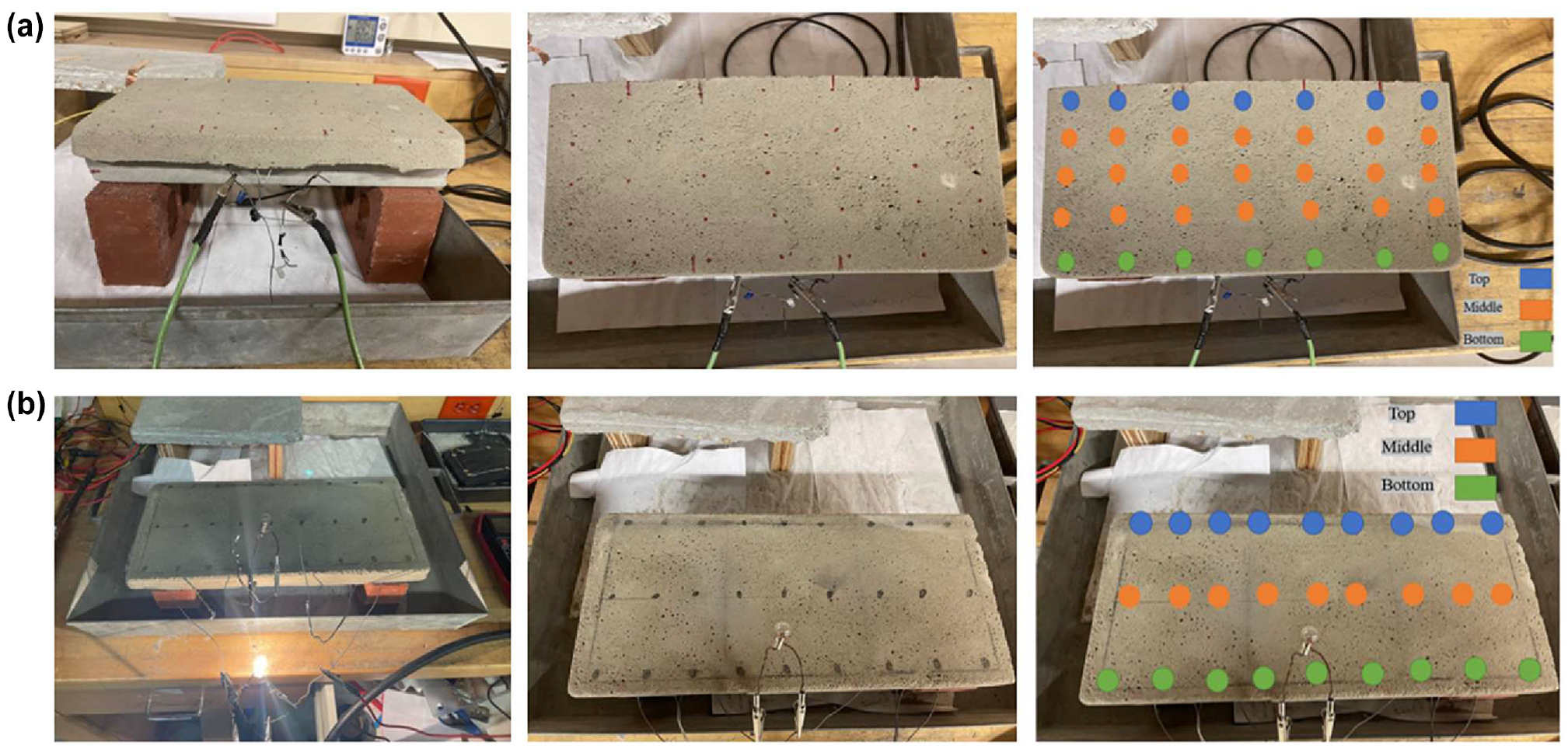
Measuring and recording the rise in temperature for the two concrete electrically heated pavement system (EHPS) samples: (a) sample 1 of concrete EHPS with one rubber pad and (b) sample 2 of concrete EHPS with two rubber pads.
Results
Results of the Exposed Rubber Pads
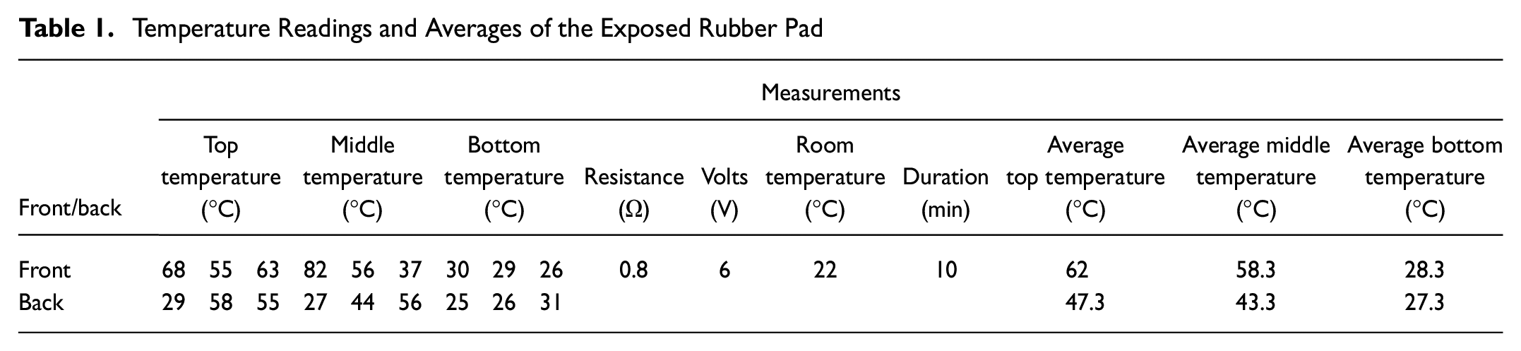
Temperature Readings and Averages of the Exposed Rubber Pad
Initial observation for temperatures of an exposed rubber sample.
Statistical Comparison: Copper versus Galvanized Steel in an L-Shaped Circuit
Results of the Grooved Rubber Pads
Observation of temperatures of the front and back sides of the L-shaped circuit with copper wire for 60 min.
Observation of temperatures of the front and back sides of the L-shaped circuit with galvanized steel wire for 60 min.
Observation of temperatures of the front and back sides of the U-shaped circuit with galvanized steel wire for 60 min.
Special cases for current flow: (a) U-shape electric circuit using galvanized steel wire and (b) Even distributed current flow direction.
Results of the Rigid EHPS Samples
Locations of temperature readings on the rigid electrically heated pavement system (EHPS) specimen.
Experimentation of the combined concrete and rubber sample 1 and sample 2.
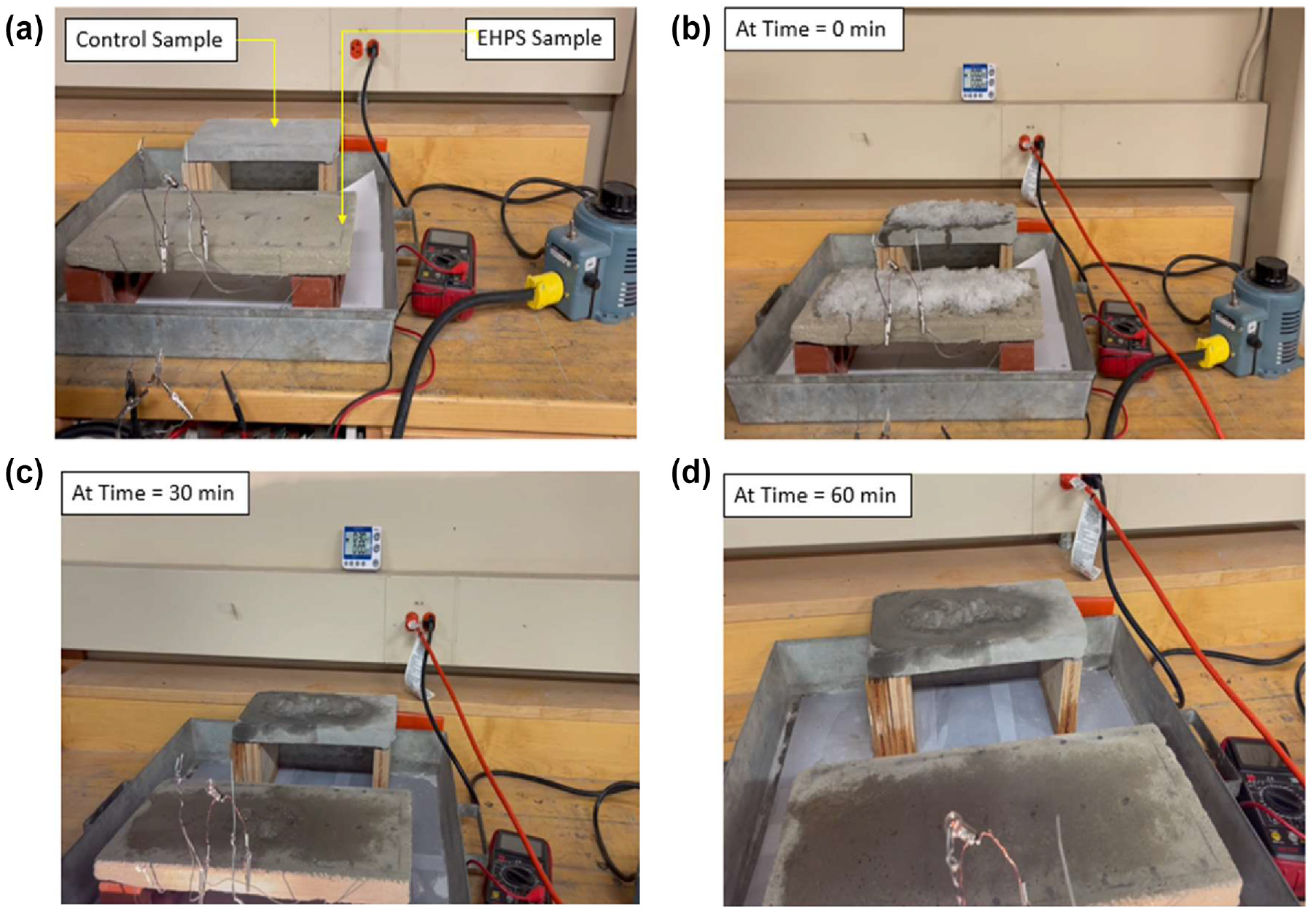
Experimental setup for testing the capability of the proposed electrically heated pavement system (EHPS) in melting snow (ice cubes): (a) ice-melting experiment setup, (b) placing the ice cubes, (c) after 30 min of turning on the circuit, and (d) after 60 min of turning on the circuit.
Observing effects of temperature increase on the melting of crushed ice at various intervals: (a) ice-melting experiment setup, (b) placing the crushed ice, (c) after 30 min of turning on the circuit, and (d) after 60 min of turning on the circuit.
Discussion
Exposed Rubber Pads
The experiment involved connecting the rubber pads to a power source, and observations were recorded for a duration of 10 min for each side of the pad. Given the study’s strong emphasis on sustainability, particularly in its economic aspects, one of its objectives is to minimize power consumption. To achieve this, the power was supplied at a very low voltage. A 6 V electric current supply proved sufficient to yield overall exceptionally elevated temperatures, as shown in Table 1. Temperature readings for both the front and back sides of the top, middle, and bottom areas of the rubber pad were recorded in degrees Celsius (see Table 1). The electrical circuit’s resistance was precisely measured at 0.8 Ω. The ambient room temperature, maintained at 22°C, was meticulously recorded to highlight the temperature contrast between the sample and its surrounding environment.
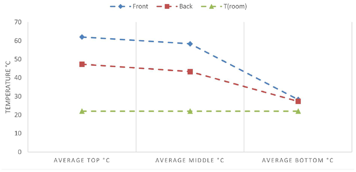
Figure 11 illustrates the temperature trends of the three areas on both sides of the rubber pad over time, with a constant supply voltage of 6 V, in comparison with the room temperature of 22°C. After 10 min, the average temperature of the top spots on the front side was 62°C, while on the back side it was 47.3°C. It is worth noting that, whether on the front or back, the top section exhibited the highest averages. Furthermore, the averages for the top and middle sections were quite close, suggesting a relatively even heat distribution on both sides. In contrast, the average for the bottom section, regardless of side, was the lowest. Overall, over time, all three strips—top, middle, and bottom—both on the front and back, surpassed the initial room temperature of 22°C.
Grooved Rubber Pads
As mentioned in the previous sections, four designs for the electric circuit were developed, which are the L-shaped with copper wire, L-shaped with galvanized steel wire, U-shaped with copper wire, and U-shaped with galvanized steel wire. The electric circuits were connected to an alternating current (AC) power source and the elevations in the temperature were recorded for different areas (top, middle, and bottom) of the circuit. The experiment spanned 1 h, with the sample continuously supplied with a very low AC electric current of 6 V. The reference point for this experiment was the ambient temperature, which measured 22.7°C. Temperature readings for the top, middle, and bottom strips of the rubber sample gradually rose above room temperature for both the front and back sides. Notably, the middle strip encompassed the largest area of the rubber sample, as indicated by the highest number of colored circles as shown in Figure 9, and therefore required precise observation. The following sections present the results for the temperature recorded using each circuit.
Figure 12 depicts the temperature progression for both the front and back sides of a grooved rubber sample with an L-shaped circuit design connected using copper wire. After 1 h of experimentation, the average temperature of the middle strip reached 46.3°C on the front side and 38.9°C on the back side. Overall, the sample’s temperature was nearly double that of the room temperature. As for the L-shaped circuit design connected using galvanized steel wire, as shown in Figure 13, the average temperature of the middle strip reached 45°C on the front side and 37.1°C on the back side. The temperature of the L-shaped circuit was almost twice the room temperature.
In examining the thermal performance of grooved L-shaped electric circuits within rubber samples, marginal disparities were observed between the temperatures recorded for copper and galvanized steel configurations (see Table 2). The mean temperatures on the front face exhibited a slight difference, with copper at 39°C and galvanized steel at 37.3°C, while on the back face, a similar trend persisted with copper recording 35°C compared with galvanized steel’s 32°C. The standard deviation values hinted at marginally higher variability in copper temperatures, suggesting minor inconsistencies in heat dissipation compared with galvanized steel. Despite these variations, the comparable electrical parameters—voltage, resistance, current, and power—across both materials indicate that the observed temperature differences are predominantly attributed to thermal conductivity variances. Subsequently, the decision to adopt galvanized steel wire for continued usage was based on its cost-effectiveness and sustainability aspects, given its notably lower cost and commendable environmental profile. This choice underscores the practicality of galvanized steel wire for sustained implementation in similar electrical circuit applications, considering its affordability and environmental impact.
Conversely, the U-shaped circuit design connected using galvanized steel wire (as seen in Figure 14) demonstrates a significant temperature increase for both the front and back sides of the rubber sample. The averages of the temperature readings for the top, middle, and bottom strips surpassed 60°C after continuous 1 h connection to an AC power supply at the same voltage of 6 V. It is evident that this circuit design exhibited a notable difference in temperature rise compared with the L-shaped designs. As a result, this design was selected for implementation in the second phase, which involved embedding the rubber pad into the concrete.
It is important to note that the uneven heat distribution in certain circuits can be attributed to the radial placement of the steel mesh. This can lead to interruptions in contact with the main copper or galvanized steel connector supplying the electric current, because the cutting and fabrication of the pad affect the flow of current and, subsequently, heat distribution. Conversely, the superior performance of the U-shaped circuit compared with other designs can be attributed to the presence of double wires in the middle of the rubber pad, effectively capturing a larger portion of the steel mesh strands and maximizing contact for a more efficient flow of electric current. This significantly contributes to the improved heat distribution observed in this configuration (as illustrated in Figure 15).
Rigid EHPS Samples
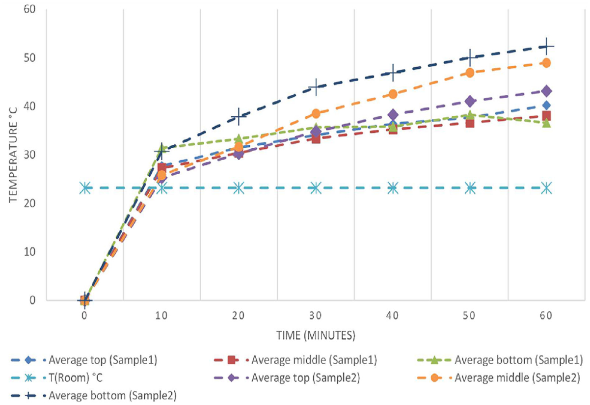
The second phase of the experiment focused on monitoring the temperature increase across the entire surface of the concrete sample. The concrete sample represents only the top stratum in the rigid pavement where the rubber pads will be embedded; therefore, the thickness of the concrete sample was limited to 3 cm. Once it was confirmed that the rubber pad, along with its U-shaped electric circuit, could efficiently generate and evenly disperse a substantial amount of heat, it was embedded into the concrete samples. The concrete samples were then turned upside down, and only the side forming the road surface (facing the vehicles and snow accumulation) was subjected to testing. For precision in temperature measurements, the top, middle, and bottom strips were marked with blue, orange, and green circles, respectively, as previously done (see Figure 16). After connecting the circuit to a power supply of 6 V for a duration of 1 h, for sample 1 (single-padded with dimensions 20 × 30 × 3 cm), the top, middle, and bottom strips recorded temperatures of 40°C, 38°C, and 36°C, respectively (as shown in Figure 17). For sample 2 (double-padded with dimensions 20 × 40 × 3 cm), after 1 h of testing, the top, middle, and bottom strips recorded slightly higher temperatures of 43°C, 49°C, and 52°C, respectively, in comparison with the measured room temperature of 22.4°C (as shown in Figure 17). These findings clearly indicate the successful generation of a significant amount of heat, with an evenly distributed pattern observed across the concrete sample. It is noteworthy that this impressive outcome was achieved using a very low voltage.
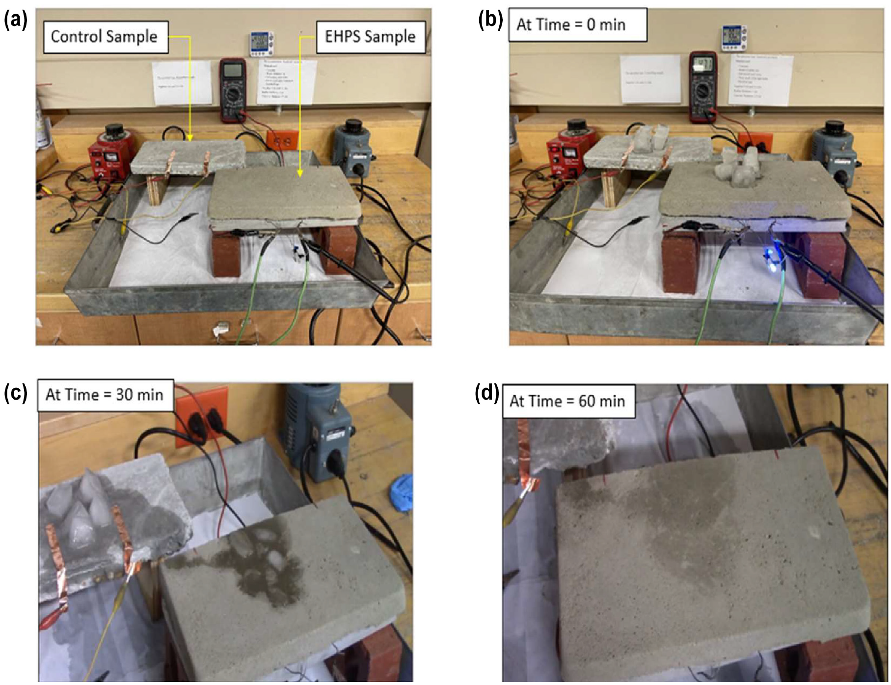
The performance of the proposed rigid EHPS was further assessed by subjecting the pavement surface to snow accumulation. The experimental setup in Figure 18 illustrates two pavement samples. The first (front) sample is a rigid EHPS constructed using two rubber pads enclosing U-shaped electric circuits and connected to a power supply of 6 V. The second (back) sample is a concrete rigid pavement, used as a control sample. To standardize the testing conditions for both samples, the control sample was also connected to the same power supply. The surfaces of the two samples were covered with an equal number of whole and crushed ice cubes, simulating conditions worse than snowfall, as ice cubes have a lower temperature and are harder to melt than snowflakes. Figure 19 showcases the progression of the experiments through images captured at different time intervals. After 30 min, using a power supply of 6 V, the ice cubes have almost disappeared from the surface of the proposed EHPS, while they remain intact and prominent on the regular concrete pavement. This indicates the superior capability of the proposed EHPS to melt snow efficiently using smaller amounts of electric energy under extreme cold conditions.
Conclusion
This study aimed to evaluate the effectiveness of a novel EHPS for snow melting using WRT, providing a sustainable and environmentally friendly alternative by utilizing the significant annual waste of rubber tires that would otherwise end up in landfills or be incinerated. This method prevents the depletion of raw materials such as carbon black and carbon fiber.
The rubber samples, connected to a 6 V power supply, exhibited sufficient and satisfactory heat distribution. Exposed rubber pads reached average temperatures up to 62°C. For the grooved pads, the L-shaped circuit with copper wire achieved front and back temperatures of 39°C and 35°C, respectively, while the galvanized steel wire reached 37.3°C and 32°C, respectively. The U-shaped circuit with galvanized steel wire exceeded 60°C for both the front and back sides. Good heat distribution was achieved for both faces of the rubber pads, with temperatures remaining even across the top, middle, and bottom sections. The grooved design proved to be better than the exposed design as it does not require removing the entire top rubber layer to reach the steel wire mesh, saving time and making the method more applicable while protecting the steel wire mesh from damage during rubber layer removal.
In the analysis, the recorded temperatures for sample 2 (20 × 40 cm) revealed a gradient, with the top, middle, and bottom temperatures measured at 43°C, 49°C, and 52°C, respectively. This significant temperature differential, especially the nearly 10°C difference between the top and bottom layers, highlights a crucial area for further investigation. The variance observed can likely be attributed to the distinct thermal conductivity properties of the rubber pads and concrete used in the sample. Additionally, the positioning and distribution of the rubber pads within the concrete matrix may influence the heat conduction and retention characteristics within the sample. Nonetheless, it is important to note that even the top temperature in sample 2 was twice that of the control sample, underscoring the effectiveness of the heating system despite the temperature gradient observed.
In summary, this innovative EHPS offers a viable alternative to traditional de-icing methods by leveraging the electrical and thermal properties of recycled materials, enhancing pavement safety and durability during winter while contributing to environmental conservation and resource efficiency.
Footnotes
Acknowledgements
We express our sincere gratitude to Professor Mohamed AbdelRaheem for his brilliant idea, which served as the foundation for this research endeavor. His guidance and insightful contributions significantly enriched the study. Additionally, we extend our appreciation to all the professors in the Civil Engineering Department at the University of Texas Rio Grande Valley (UTRGV) who provided valuable assistance and support throughout the course of this project. Their expertise and encouragement played a crucial role in shaping the outcomes of our research.
Author Contributions
The authors confirm contribution to the paper as follows: study conception and design: I. Radwan, M. AbdelRaheem; data collection: I. Radwan; analysis and interpretation of results: M. AbdelRaheem, I. Radwan, draft manuscript preparation: I. Radwan, M. AbdelRaheem. All authors reviewed the results and approved the final version of the manuscript.
Declaration of Conflicting Interests
The author(s) declared no potential conflicts of interest with respect to the research, authorship, and/or publication of this article.
Funding
The author(s) received no financial support for the research, authorship, and/or publication of this article.