
Abstract
We review the development of wind turbines for generating electricity from the late 19th century to the present, summarizing some key characteristics. We trace the move from two and four blade wind turbines to the three blades common today. We establish that it was not the governmental-funded wind programs with its large-scale prototypes of the 1970–80s that developed into the commercial turbines of today. Instead, it was the small-scale Danish wind turbines, developed for an agricultural market, that developed into the commercial turbines of today. And we show that much of what we know today about wind turbine design was known by the 1930s and certainly well known by the late 1950s. This work is divided into two parts: the first part takes up the development from the first electricity producing wind turbines through to the 1960s and a second part on development from the 1970s onward.
Introduction
Since the oil crises of the 1970s and the following Great Wind Revival of the 1980s, wind turbine design has evolved markedly, settling on a characteristic configuration using rotors with three blades, upwind of the tower, in steadily increasing size. Today, modern wind turbines, along with solar photovoltaics, are the principal source of new electricity generating capacity.
Aim of paper
We briefly trace the development of modern wind turbines from the late 19th century to the present in Europe and North America. Much has been written about the history of wind power in both the academic and popular press. Libraries contain entire shelves devoted to books on the history of the Dutch or European windmill, the American water-pumping windmill, and now modern wind turbines.
This work is adapted from two chapters in “Wind Energy for the Rest of Us” by the first author (Gipe, 2016) and summarizes the key characteristics of wind turbine development in tabular form, showing that the technology has converged to a common configuration: Horizontal-axis wind turbines with a three-blade rotor upwind of the tower. We introduce the metric of specific area (m2;/kW) as a defining parameter for wind turbines used on land.
By revisiting historical wind turbines and development threads, we will try to shed light on what has developed into the large successful commercial wind turbines od today. We have also expounded on two relatively little-known post World War II wind turbines; one in Germany and one on the Isle of Man.
This work is divided into two parts: the first part (Gipe and Möllerström, 2022) covers the time from early electricity-generating wind turbines through the 1960s, and the second part covers the time from the 1970s onward.
Limitations
We focus only on the development of onshore wind turbines and we focus only on development in Europe and North America. While Vertical-Axis Wind Turbines are mentioned, they are not discussed at length. These are discussed elsewhere (Möllerström et al., 2019). Nor do we discuss the development of wind turbines with only one blade, or ducted wind turbines. Both strategies fall outside the main stream of wind turbine development.
The great wind revival
In 1973 the world awakened to find oil embargoed for the first time. Many nations launched crash programs to develop “alternatives,” including wind energy and nuclear power.
After the oil embargo rekindled interest in wind energy, two distinct—and often warring—camps sought to make wind energy work—and to profit by it. These camps reflected the fault lines in society. One camp represented the establishment thinking of the day. They fostered a centrally-conceived and centrally-directed program acting through aerospace contractors or electric utilities to build large wind turbines. This was the way it had always been done. They would develop wind technology in the same manner as the Manhattan project developed an atomic bomb—from the top down. They would choose the designs, choose the contractors, and choose the host utilities.
The second camp, led by an assortment of political activists and entrepreneurs, believed that the development of wind energy should be open to everyone, because they wanted to participate. After all, no one owned the wind. This camp also didn’t trust the “establishment” to get the job done. They argued that incrementally developing wind turbines would be better suited to the skills and knowledge of the time and to the small and medium-size companies that would most likely make wind energy flourish. They thought wind energy should grow from the bottom up, not from the top down. The decisions made during that period still rankle even today. And the fight over who owns the right to develop and use wind energy is still very much alive.
The top-down strategy focused on multi-megawatt wind turbines that would be built by the aerospace industry and operated by electric utilities. The names of the companies involved read like a Who’s Who of the Western Aerospace Industry. In the United States, Hamilton Standard, General Electric, Westinghouse, and Boeing all attempted to develop large wind turbines for the US Department of Energy (DOE). The niche was filled by MBB (Messerschmidt-Bölkow-Blohm) and MAN (Maschinenfabrik-Augsburg-Nürnberg) in Germany, and similar companies in Sweden, Britain, and elsewhere.
Bringing NASA down to Earth
After the moon landings, NASA (the National Aeronautics & Space Administration) was scrambling to redefine itself, to find new “missions,” when opportunity struck in the form of the first oil embargo. What began as mere tinkering by researchers at the agency’s Lewis research center near Sandusky, Ohio quickly evolved into the most costly wind energy R&D program in the world (Baldwin and Kennard, 1985).
NASA began by consulting with Hütter and Putnam and studying the operation of Juul’s machine at Gedser. In the end they started down a path blazed years before by Putnam. The result, the Mod-0, resembled neither Hütter’s lightweight, flexible, downwind design nor Juul’s rigid three-bladed upwind design. NASA’s Mod-0 incorporated none of the lessons from Europe, while abandoning Putnam’s most significant design element, his hinged blades. Westinghouse, the contractor on the Mod-0, was subsequently hired to build a more powerful version, the Mod-0A, for extended field tests (see Figure 1).
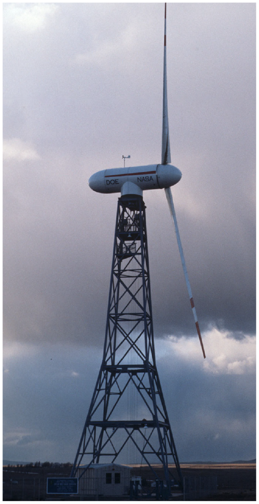
Mod-0A. One of four NASA Mod-0A turbines installed in pilot projects across the United States. The Mod-0A used a two-blade rotor 38-m (125-ft) in diameter to drive a 200 kW generator. This turbine was installed in 1977 for a small municipal utility in Clayton, New Mexico until it was removed in 1982. Note the lattice tower and how the blades are swept downwind, giving the spinning rotor the shape of a cone oriented downwind. This is characteristic of downwind rotors. The turbine was in operation when this photo was taken in 1979.
After the Mod-0A, NASA and US DOE scaled up the configuration and hired General Electric to build the Mod-1, a machine 2.5 times the size of the Mod-0A and only slightly bigger than Putnam’s machine. Like its predecessor, the Mod-1 bore two rigid blades downwind of the tower (see Figure 2). Installed in 1978 on a ridge of the Appalachian Mountains near Boone, North Carolina, the Mod-1 was the first wind turbine to stir national controversy. Low-frequency noise from the downwind machine disturbed neighbors in sheltered valleys down slope. The noise was attributed to passage of the blades through the turbulent wind shadow behind the cluttered truss tower, a problem that was noted earlier on the Mod-0 at Sandusky but not corrected. GE’s Mod-1 never performed as expected and never logged any operating hours before being quickly removed. It ranks as the world’s worst performing large wind turbine ever built.
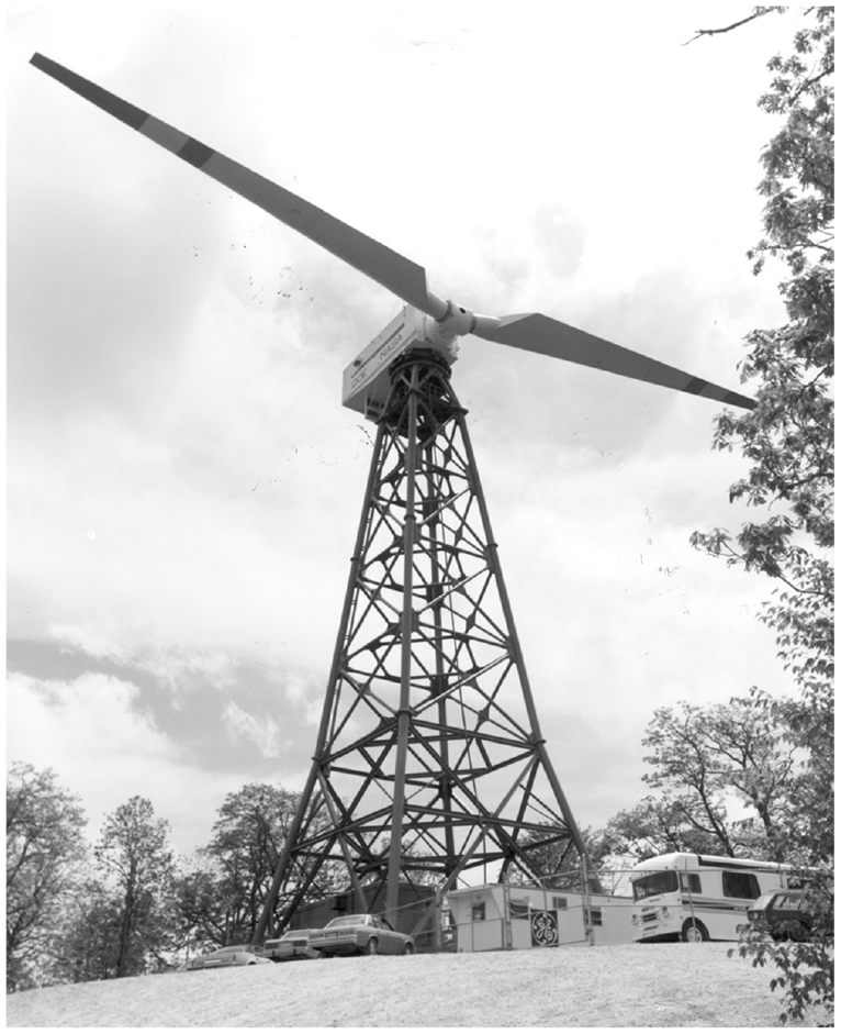
GE’s Mod-1. The US DOE large turbine program got off on the wrong foot with General Electric’s Mod-1. The 61-m (197-ft) diameter, two-megawatt turbine proved disastrous, leaving a record of noise complaints that still dogs the wind industry worldwide three decades after it was removed for scrap. Worse, the turbine logged no recordable operating hours during its brief period of testing, worsening the ignominious failure. (USDOE).
Despite the problems that plagued the Mod-1, NASA and DOE determinedly proceeded with the next machine in their program, Boeing’s Mod-2. The Mod-2 was nearly three times the size of the Mod-0 and more than twice the size of the Mod-1. Four Mod-2 turbines were installed in the DOE program. Another was delivered to Pacific Gas & Electric (PG&E) in California. The turbine operated sporadically from 1982 to 1988. In contrast to commercial wind turbines that must be available for operation more than 98% of the time, PG&E’s Mod-2 was available for operation only 37% of the time. Worse yet, it generated only 40% of the output possible if the turbine had operated reliably (see Table 1).
Historical development of large wind turbines .
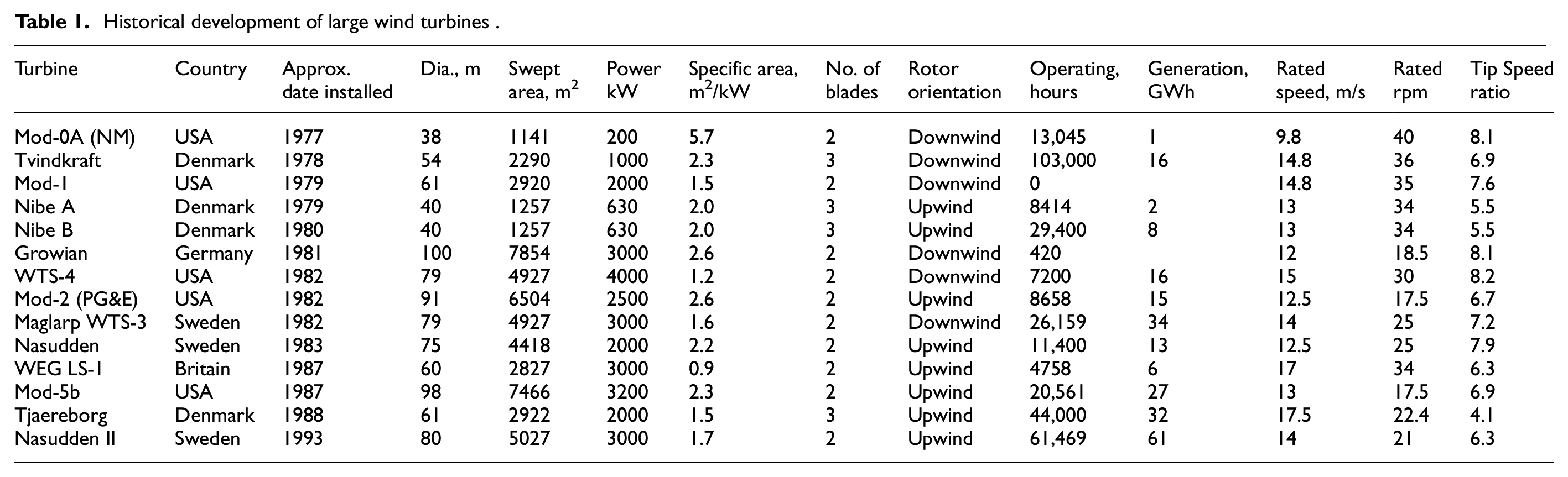
All the Mod-2s were eventually scrapped, with the PG&E turbine meeting the most spectacular fate. Concluding that it was too costly to dismantle, PG&E felled the tower like a lumberjack cutting a giant redwood. After a series of explosives severed the tower, the last Mod-2 crashed to the ground in front of television news crews helpfully assembled by PG&E.
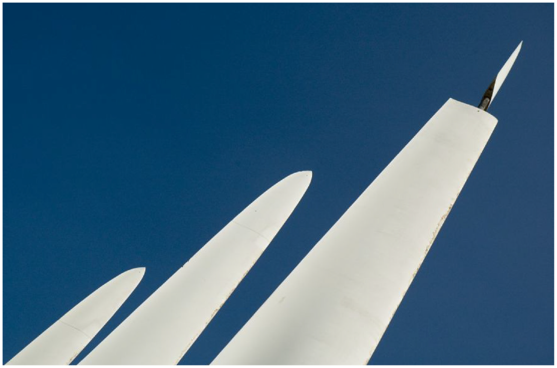
The Mod-5b contract, the culmination of NASA & DOE’s large turbine program, was again awarded to Boeing (see Figure 3). The Mod-5b performed better than other turbines in DOE’s program, but after 4 years of operation delivered only 70% of the revised projection for the site.
Boeing Mod-5b. The most successful of US DOE’s large wind turbines, the Mod-5b marked the end of the line for the program. Though installed nearly one-half decade later, the turbine was as large as Growian with a rotor 98 m (320 ft) in diameter. Unlike Growian, the Mod-5b used a two-blade rotor upwind of the tower, and instead of the fiberglass used in Growian’s blades, the Mod-5b used steel. Yes, steel. It was once considered a blade material.
NASA & DOE had expected to win economies-of-scale by jumping directly to large turbines rather than take the time to incrementally scale up smaller turbines after they had become more reliable. Researchers instead found diseconomies-of-scale due to the costly specialized components required for the limited number of large machines. These one-of-a-kind turbines also needed specialized equipment to service them. Thus the technology was troublesome from the start, and when it failed, it took a long time to fix.
As French wind turbine designer Constantin had suggested in the 1920s, and Vadot and Hütter had argued in the 1950s, there were clear advantages to operating large numbers of medium-sized machines rather than one large turbine. If one of the smaller machines failed, the remaining turbines could continue to operate, generating electricity—and revenues—for their owners until the non-operating turbine could be brought back on online. However, when one large turbine failed, it removed a significant portion of capacity from the generating mix and contributed to the conventional wisdom that wind would never work commercially. This was the Achilles heel of both the United States and the German R&D programs.
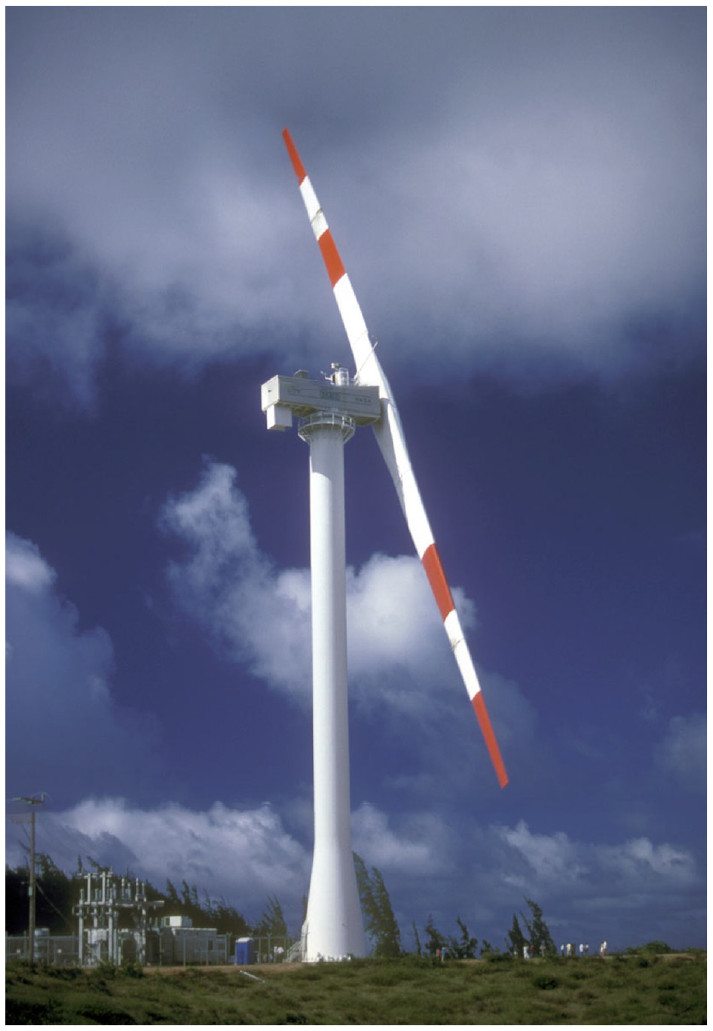
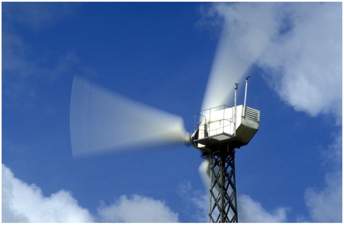
Unlike the aerospace contractors in the R&D program, who were content to go from one contract to the next, Westinghouse commercialized their work on the Mod-0A during the mid-1980s. In 1985 they installed 15 of their Westinghouse 600 models at Kahuku Point on Oahu. Westinghouse abandoned the downwind orientation of the Mod-0A, putting their teetered rotor upwind of a new tubular tower (see Figure 4). They increased the rotor’s swept area by 30% and tripled the generator rating for the windy Hawaiian site.
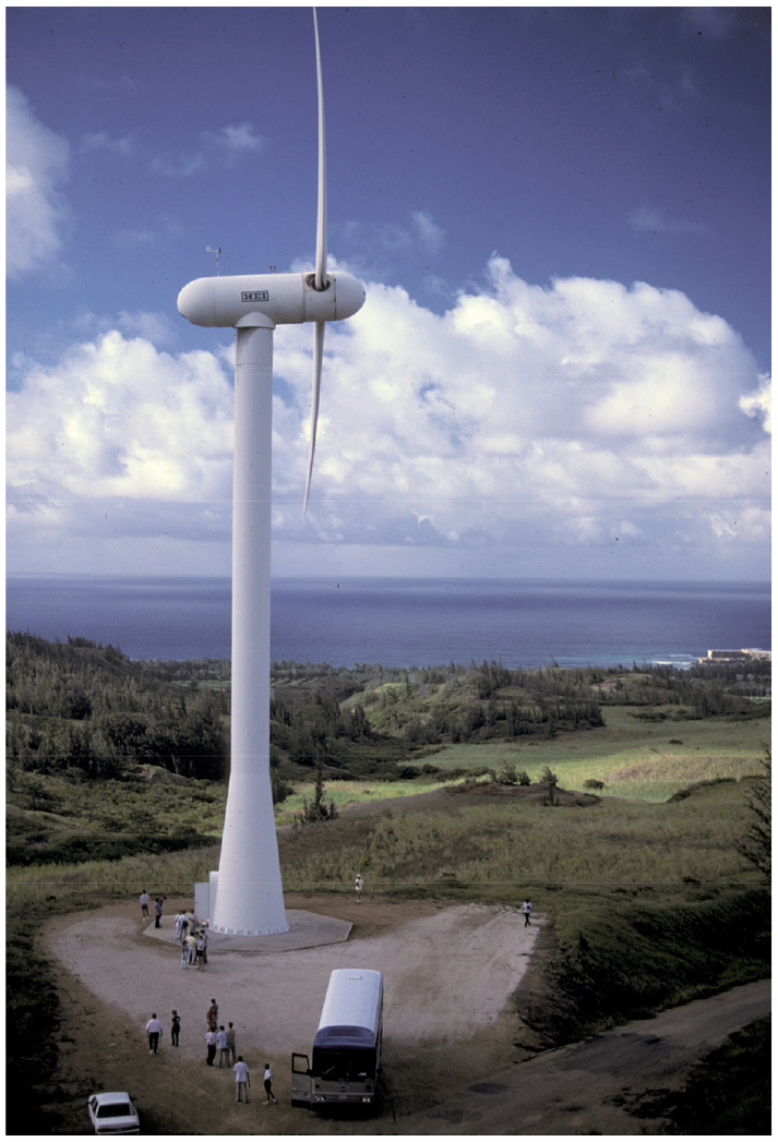
Westinghouse 600. One of the more successful ventures resulting from the US research & development effort was Westinghouse’s 600 kW model. Fifteen turbines were installed in Hawaii and operated for a number of years. They were eventually removed and two surviving turbines now stand at the National Renewable Energy Laboratory at Rocky Flats, Colorado. Late 1980s.
In 1989, the Westinghouse turbines were available for operation 80% of the time, a performance superior to that of most experimental turbines of the era, but still well below that of much smaller but fully commercial turbines already operating in California and Denmark. After unsuccessfully attempting to sell more turbines, Westinghouse closed their wind program.
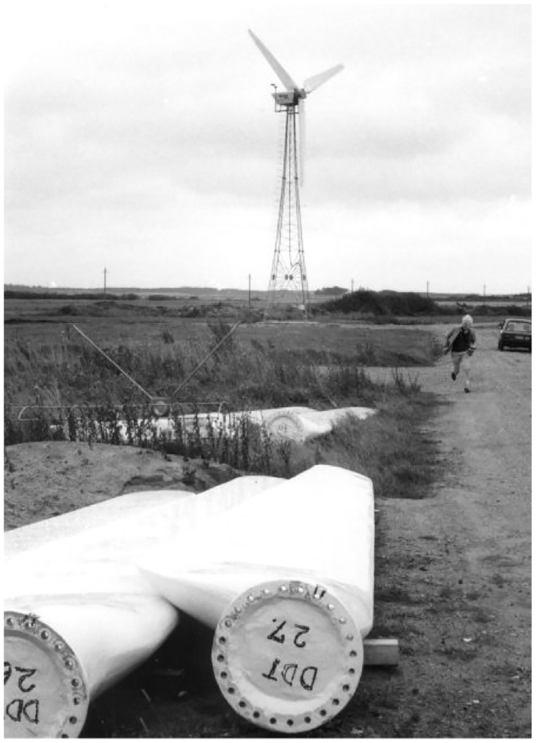
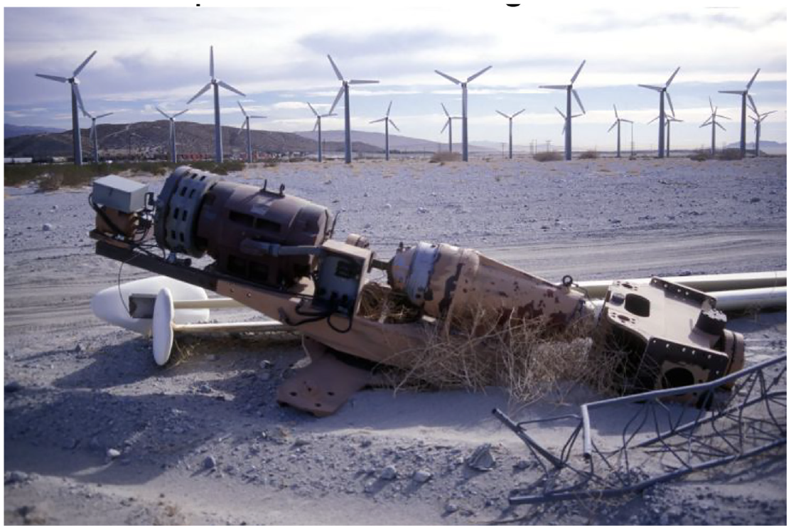
While NASA & DOE were pursuing the Mod program, Hamilton Standard went out of the country to win a portion of a Swedish R&D contract for development of another large turbine (Möllerström, 2019). Sweden, like the US and Germany, had its focus on governmental-funded large prototypes. The Connecticut aerospace contractor designed the rotor for both Sweden’s WTS-3 and the US Bureau of Reclamation’s WTS-4 (see Figure 5). Hampered by bureaucratic and technical problems, the WTS-4 operated intermittently from 1982 until 1994 at its site near Medicine Bow, Wyoming when it was severely damaged after one of the blades struck the tower. The demise of the WTS-4 brought to an end the era of large wind turbines in the United States.
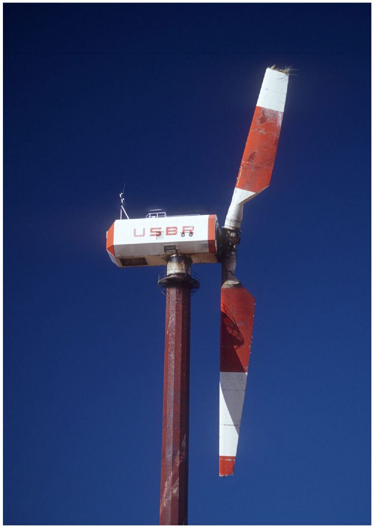
Hamilton Standard WTS-4. One of the most poorly performing large wind turbines developed by aerospace contractors during the 1980s. The WTS-4 had an extremely high specific power of 812 W/m2 and generated only 16 million kWh during its 7000 hours of operation before the teetered, downwind rotor struck the tower in 1994. Late 1990s.
Germany’s Growian
During the late 1970s Germany’s ministry for technological development BMFT (Bundesministerium für Bildung und Forschung) called Hütter out of retirement to design a new wind program (Feustel et al., 1980; Heymann, 1995). He concluded that his 1960s approach still represented the state-of-the-art, and that with the technology gained since his turbine had been dismantled, the design could be scaled-up to multi-megawatt size. Thus Growian (Grosse Wind Energie Anlage or large wind turbine) was born (see Figure 6).
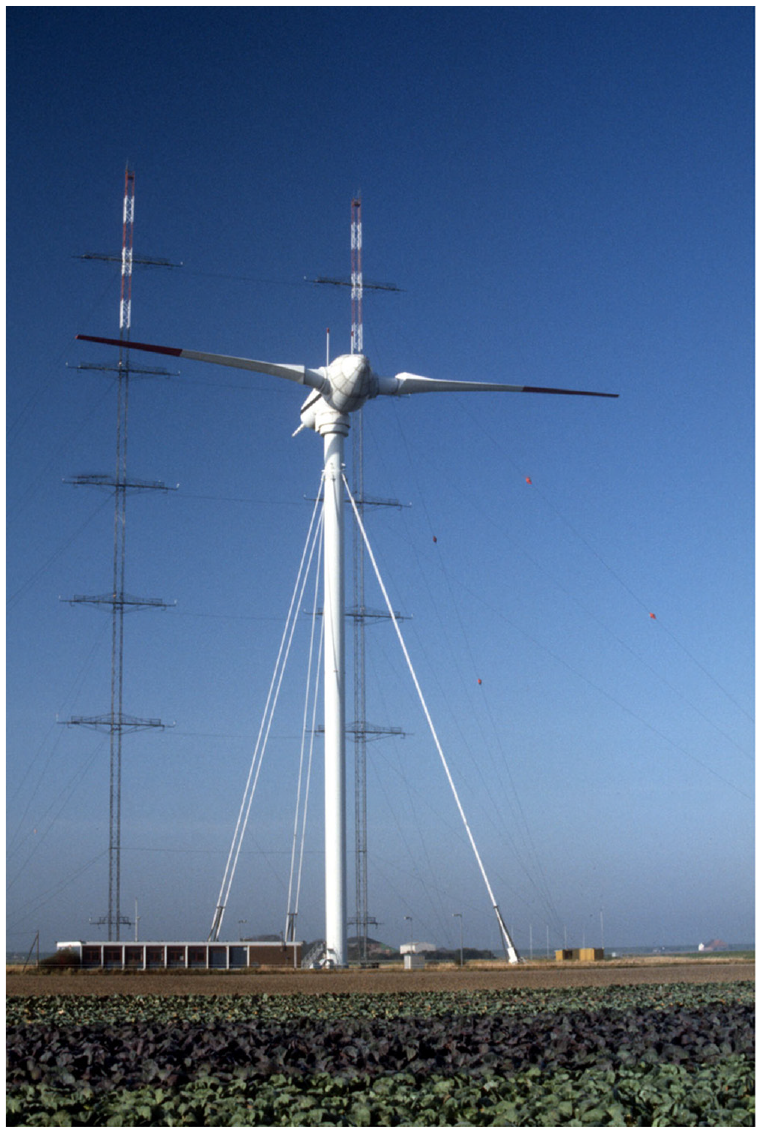
Growian. One of German engineering’s most spectacular failures was Growian (Grosse Wind Energie Anlage). The downwind, 100-m (330-ft) diameter turbine operated only 400 hours between the time it was installed in 1983 and when it was taken out of service in 1987. Growian operated even less than the Smith-Putnam turbine in Vermont in 1945. It was more than two decades before German manufacturers again ventured to this size. The two guyed towers are meteorological masts at what was to become the Kaiser-Wilhelm-Koog test center. 1987.
Hütter remained cautious and as with his early experimental turbine, recommended loading the rotor lightly. He suggested that a rotor 80 m in diameter be used to drive only a 1 MW generator. But the contractor had a much grander vision.
In 1983, MAN completed installation of a 3 MW turbine 100 m in diameter. They realized their mistake even before installation was complete. The proposed height of the tower exceeded existing crane capacity, forcing the company to seek approval for a shorter tower. MAN did succeed in building the world’s largest wind turbine—its nacelle alone weighed as much as a jumbo jet—but they also led German engineering to its most spectacular aeronautical failure. In the end Growian cost nearly twice that estimated and was dismantled in 1987 after operating only 420 hours. To save face after the highly public failure, the project was labeled a “success” by all those involved.
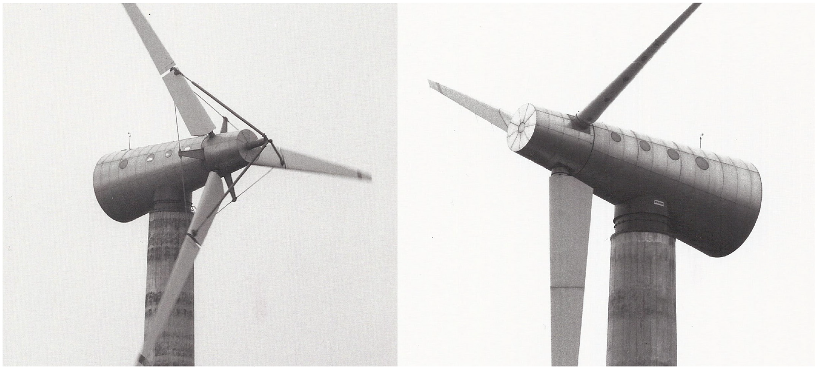
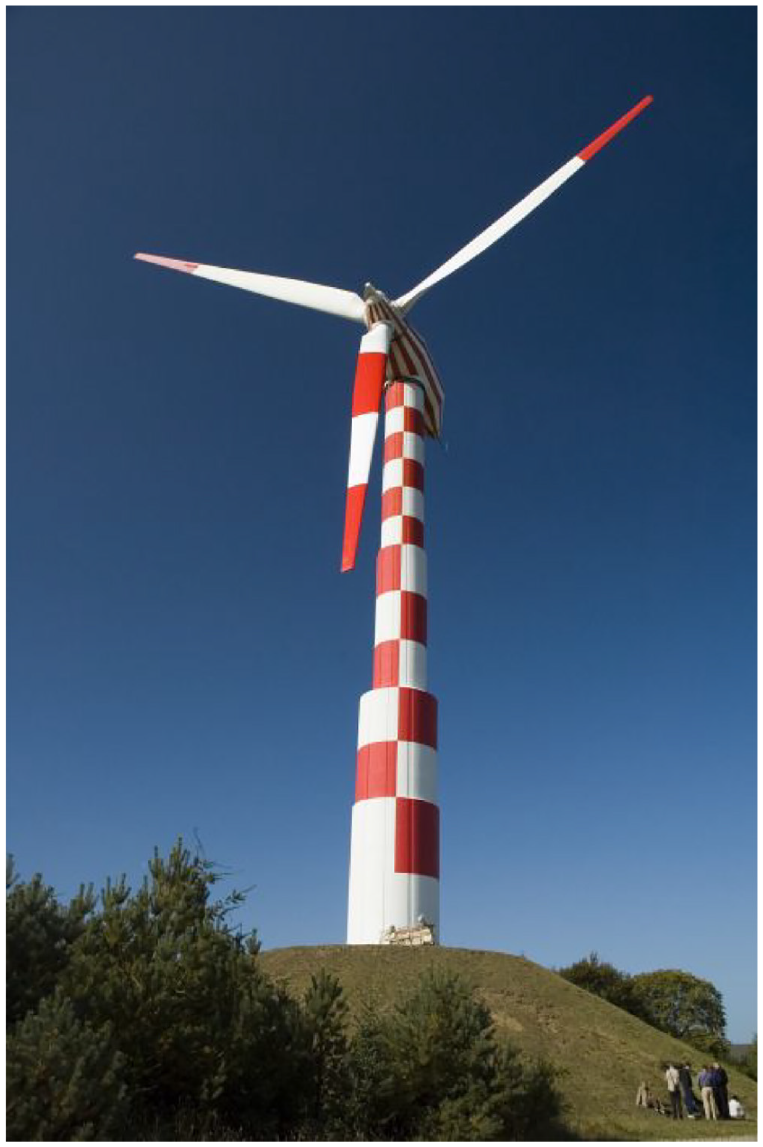
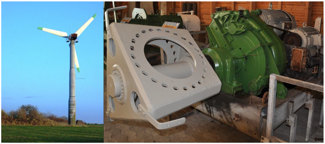
MAN tried an encore with two smaller turbines, the WKA 60 for the island of Helgoland off the northwest German coast (see Figure 7) and the AWEC 60 for Cabo Villano in Spain. Unlike Growian, the two machines used a three-blade upwind rotor that more closely resembled Danish machines than any of the Hütter-derived designs. Proponents of the turbines argued later that these machines were never intended to compete commercially. They were only for demonstration and testing.
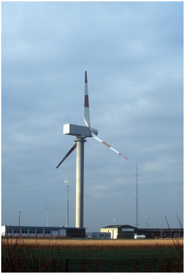
MAN WKA 60. The boxy nacelle on the 60 m (197-ft) diameter upwind turbine looks like a Würst-stand on a stick as one critic called it. Shown here at the Kaiser-Wilhelm-Koog test center in northern Germany, the same site where MAN’s ill-fated Growian had been installed earlier. The turbine was not operating when this photo was taken in the late 1990s.
Denmark: Going beyond Juul
Denmark could never afford the lavish R&D programs seen in the United States, Germany and Sweden. There was more pressure—or expectation—that what was built had to work. Unlike the United States and Germany, Denmark took the Gedser approach and scaled it up to a size more in keeping with their budget and technical capabilities. The result was the Nibe twins, two 630-kW turbines on the Limfjord at Nibe, Denmark (see Figure 8).
Nibe A & B. The twin 630 kW turbines at Nibe, Denmark. Nibe A (left) used a 40-m (130-ft) diameter upwind rotor braced with struts and stays patterned after those at Juul’s Gedser mill, however the outboard section of each blade changed pitch unlike Gedser’s fixed-pitch blades. Nibe B (right) used a “modern” rotor with full-span pitch control. Nibe A generated 2 million kWh and Nibe B generated 8 million kWh before the turbines were taken out of service 13 years later. Though functional, the nacelles reminded Danes of a mousetrap. 1980.
The Nibe turbines were less than three times the size of Juul’s Gedser mill. The objective was to compare two different configurations. Nibe A, with its prominent struts and stays, resembled the machine at Gedser. Nibe B, in contrast, used a fully cantilevered blade that could be operated with variable pitch. However, the blades developed for Nibe were not like those used at Gedser, and more significantly were not like those used previously by Hütter in Germany (see Figure 9).
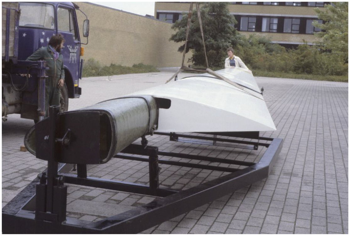
Volund blade. Danish manufacturer Volund built this blade using a filament-wound spar. Filament winding was being used for missile casings in the aerospace industry and was an advanced technology in 1980. However, Volund—and this blade technology—were not successful. Successful blade technology came from a much more prosaic source: the Tvind School. 1980.
Nibe A operated briefly before the rotor needed repair. Still, it operated more hours than GE’s Mod-1, MAN’s Growian, and Hamilton Standard’s WTS-4. Nibe B operated more or less successfully, racking up more operating hours than any R&D wind turbine of the early 1980s. The two turbines together cost less than two-thirds the cost of GE’s single Mod-1.
On the other side of Denmark, Elsam, the utility serving Jutland, scaled-up the Nibe B design for the Danish R&D program. After several years of fitful operation, the 2 MW turbine at Tjæreborg finally reached 80% availability in 1992 (see Figure 10). By the time the turbine was removed in 2000—much in the way of PG&E’s demolition of its Mod-2—the performance of Elsam’s turbine had far exceeded that of any other wind turbine installed in any large wind turbine development program.
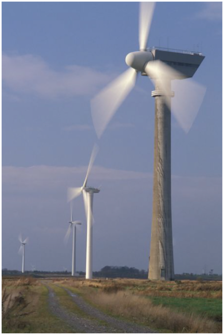
Tjæreborg. The test site at Tjæreborg on the west coast Denmark’s Jutland peninsula hosted several megawatt-scale turbines in the late 1990s. The oldest turbine, the 2 MW, 61-m diameter turbine on the concrete tower in the foreground was installed in 1988. After more than a decade of service, it had operated more than 44,000 hours, becoming the longest-running wind turbine in any national or utility-sponsored R&D program worldwide. Note that all the turbines in this photo are in operation, a signature of the Danish program. 1998.
Even so, Elsam’s Tjæreborg prototype would be out shined by an unlikely turbine with an unlikely origin installed a decade earlier. Moreover, it wasn’t the turbines at Nibe or Tjæreborg that gave us the technology used today, says Danish wind pioneer Maegaard et al. (2013) in Wind Power for the World. The technology that succeeded came from an unexpected source.
Denmark’s rebels
Following the first energy crises, Denmark was considering where, not whether, to build its first nuclear power plant. There were two small experimental reactors at Risø National Laboratory, the same Risø that later would become famous for its role testing “small” wind turbines. It was the turmoil around this pending decision that led to the famous Danish logo—Atomkraft?-Nej Tak! (Nuclear? No Thanks!) recognized worldwide (Smiling Sun, n.d.).
The Danish state’s move toward nuclear led nuclear opponents and renewable energy activists to join together and take matters into their own hands. They decided to develop wind energy themselves. Thus, a renewable energy revolution was born.
Danish carpenter
Christian Riisager committed the first act of rebellion when in 1975 he connected his wind turbine to the grid. It was the first interconnected wind turbine in Denmark since Juul’s Gedser mill was installed for the regional utility two decades before. Riisager connected the turbine to the distribution system without authorization, and without utility or planning approval. He just did it—and ran his kilowatt-hour meter backwards (Karnøe and Garud, 2012; Maegaard et al., 2013).
Though the story may be apocryphal, it illustrates the rebellious attitude of Danish wind pioneers at the time. Decades later in the United States, rebellious renewable activists sometimes still found it necessary to connect their small wind turbines and rooftop solar panels to the grid without approval in what was called at the time a “guerilla” movement.
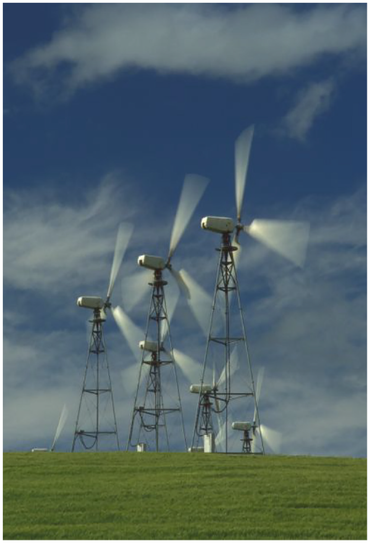
Subsequently Riisager built two 22 kW turbines in 1976 that he sold commercially. As a carpenter and as a Dane, Riisager built with what he knew best. He made his blades out of wood, and he emulated the mill at Gedser by bracing the rotor with struts and stays (see Figure 11). He used fantails to orient the 10-m rotor into the wind.
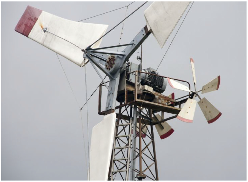
Riisager. One of the pioneering Danish wind turbines during the great wind revival of the 1970s and early 1980s. Laminated wood blades, struts and stays reminiscent of Juul’s Gedser mill, and fantails for orientation from the la Cour tradition are all found on this 30 kW version of Christian Riisager’s turbine at the Energimuseet, the Danish Museum of Energy near Bjerringbro. Hundreds of derivatives of Riisager’s design were installed in California and Denmark. Some were still operating in Californian’s Altamont Pass in the mid 2010s.
In North America in the mid to late 1970s, most activists and entrepreneurs were either rebuilding used wind turbines from the 1930s or they were designing small, household-size wind turbines. Everyone envisioned a market among “rugged individualists” who wanted to generate electricity for their own home or farm. They didn’t imagine building wind turbines large enough to generate electricity to feed the grid for powering the entire community. The United States wouldn’t see turbines of the size Riisager was building for several years (see Table 2).
Wind turbines independently developed in the mid-1970s to early 1980s.
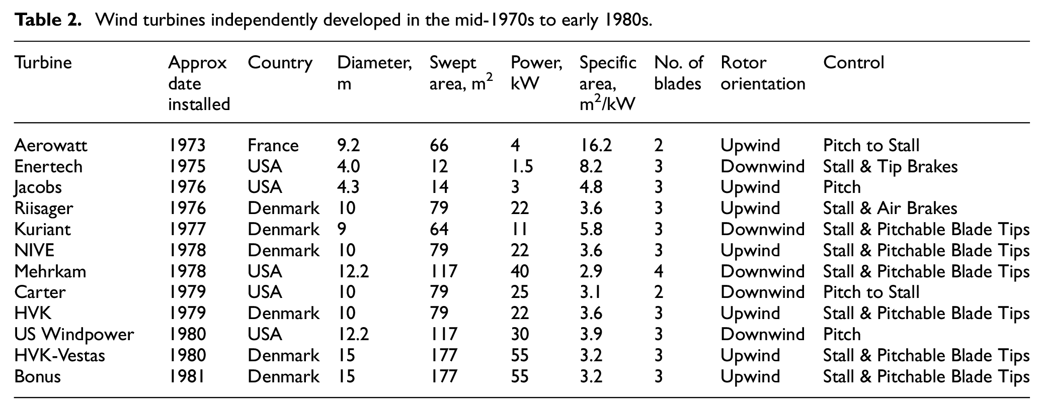
Meanwhile, Riisager’s turbines and those of competitors were steadily growing in size as well as number. This would have a significant effect on later Danish energy policy because wind turbines were now producing commercial quantities of electricity. By 1979 there were 24 wind turbines operating in Denmark, representing more than 700 kW. Of these, three-fourths were Riisager’s (Elmuseet et al., 2011).
While a direct descendent of Juul’s Gedser design, the configuration used by Riisager and his imitators presented technical challenges that limited its ability to be scaled up further. The passive fantails didn’t allow direct control of the turbine’s yaw. While simple, they didn’t permit the operator to turn the turbine out of the wind when needed, for example, to service the machine. Similarly, the rotor was weak if the nacelle swung around downwind of the tower. Though there were some 200 Riisager and derivative turbines operating in California alone in 1985 (see Figure 12), the design had reached a dead end. Further progress awaited steps being taken elsewhere in Denmark.
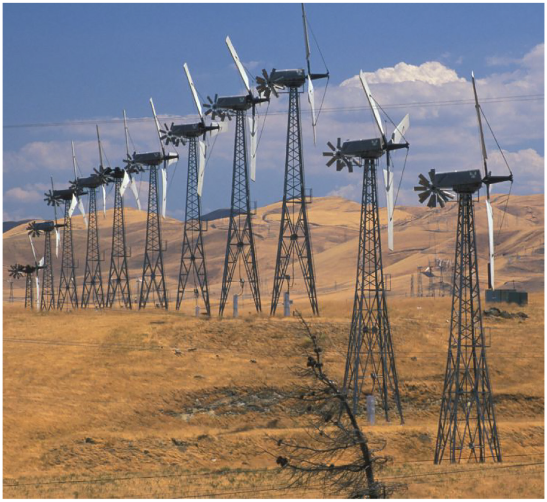
Struts and stays. Like its Danish predecessor at Gedser, the Windmatic 14S (a derivative of Christian Riisager’s original turbine) used struts and stays to brace the laminated wood blades. Note the fantail for mechanically orienting the wind turbine into the wind. The blades used pop-up air brakes to limit rotor speed in emergencies. Though ungainly, these wind turbines had operated in California’s Altamont Pass for three decades.
Tvindkraft: The giant that shook the world
Those around in the late 1970s may remember seeing magazine photographs of Danish students and volunteers carrying a massive wind turbine blade out of a tent (see Figure 13). (Karnøe and Garud, 2012; Tvindkraft, n.d.). That photo captured the world’s imagination. It was one of those rare historical moments that became a beacon to citizens everywhere who wanted to develop renewable energy by themselves, for themselves, and for their community’s benefit.
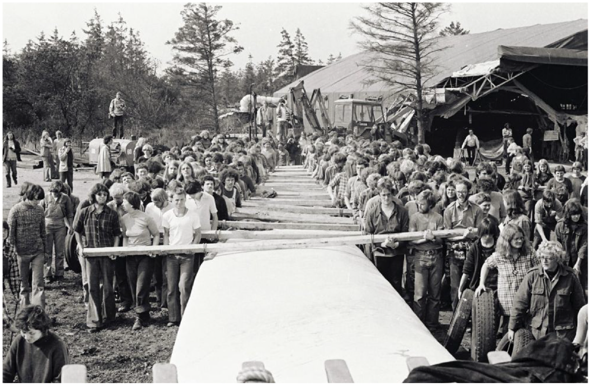
Tvind people power. The photo seen around the world in 1978 as students at the Tvind School carry one of the wind turbine blades from its assembly hall to the wind turbine. The action sent a political message: Together we are strong. We want wind power and we will build it ourselves. (Tvind School).
They were not ordinary students. They were on a mission and they knew at the time they were undertaking an historic task. They had set out to prove to the Danish government that Denmark didn’t need nuclear power, that Denmark with its long history of working with the wind could once again do so. They made another message clear too. If the Danish government wouldn’t act, the people would take the matter into their own hands, as they were doing that historic day, and build their own wind turbines.
Tvind was not an ordinary school either. Located near Ulfborg on the windy west coast of Denmark’s Jutland peninsula, the Tvind School was unlike a school in the modern sense and more in the tradition of the Danish folkehøjskole movement founded in the mid-19th century by Danish theologian N.F.S. Grundtvig. It was more like the training school founded by Poul La Cour at Askov than a public school. Not surprisingly, Tvind has had a similar influence on the development of wind energy in the contemporary era as the folkehøjskole at Askov had at the turn of the 19th century.
In the retelling of the modern wind industry’s early history, the construction of the wind turbine by Tvind and its role in pioneering modern wind turbine blades is often overlooked. It’s an uncomfortable story for many still, because the implications are so profound. How could a group of students, their teachers, and volunteers accomplish what some of the world’s most sophisticated aerospace firms with millions in research money could not? How could they build what was then the world’s largest wind turbine—a machine that has operated for more than three decades and remains in service to this day—when Boeing, Westinghouse, General Electric, Hamilton Standard, Kaman, Messerschmidt-Bölkow-Blohm, MAN and others had all failed, their turbines dismantled and sold for scrap?
The work at Tvind was taking place at the same time as NASA was developing its Mod-0A series and GE’s subsequent Mod-1. The difference in outcomes couldn’t have been starker.
The message delivered by the Tvind School so long ago was that wind energy was too important to be left to aerospace giants, electric utilities, and even to national governments. They demonstrated that unlike nuclear power, which requires massive centralized institutions, wind turbines could be built and owned by common citizens. This is a message that still resonates today.
Of course, the Tvind design team had sophisticated engineering knowledge. They and their faculty were not the Luddites some have portrayed. The school received valuable technical assistance from Helge Petersen and others from what would become Risø’s test station for wind turbines and from the Danish Technical University, for example. This was beneficial to all parties. Tvind was able to deal with some thorny technical problems, while the technical establishment gained valuable experience and hands-on knowledge of a large wind turbine outside the official Danish wind program.
And yes, they built upon a long Danish tradition with wind energy. But they were also willing to depart from that tradition when necessary. After all, they set out to build the first Danish wind turbine using long cantilevered blades instead of a rotor braced with the struts and stays like Juul had used at Gedser. They intended to build what was then considered a “modern” turbine, one that used cantilevered blades mounted downwind of the tower. Just as importantly, they were also willing to borrow good ideas from others, including from their southern neighbor, Germany. It was in this that they made their most significant technical contribution.
Tvind studiously avoided the common affliction that infects most design teams—the Not-Invented-Here syndrome. There’s a natural human tendency to want to go it alone, to be the sole inventor of a new idea and to discount the work of others and ignore the lessons they learned—often at great expense.
To build a long cantilevered blade the Tvind design team knew they needed a strong attachment at the blade’s root. Only a few decades earlier, Hütter had demonstrated just how to do so. Tvind’s development team adopted the concept as its own. The blades the Tvind team were building were no ordinary blades (see Figure 14). They were big, each was 27 m long—as long as the blade that failed on the Smith-Putnam turbine in 1945. And massive, each blade weighed 5200 kg. The blades were nearly as big as those being developed at the same time by GE for its unsuccessful Mod-1 turbine.
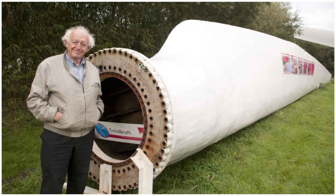
Tvind blade. The late Preben Maegaard, one of the pioneers in the Danish wind revival, stands by the root end of one of the original Tvind blades. The blade is part of Danmarks Vindkrafthistoriske Samling collection of historic Danish wind turbines and components and can be seen at the Folkecenter for Renewable Energy near Hurup, Denmark. The 27-m long blade weighs 5200 kg. Note the blade flange where it mounts to the hub. The flange and the technique for attaching the fiberglass in the blade to the flange were originally developed by Ulrich Hütter in the 1950s and 1960s. Tvind adapted the technique to its pioneering wind turbine in 1975.
Hütter’s innovation used by Tvind was to carry continuous fiberglass strands down the length of the blade to the mounting flange and wrap them around the bolt holes in the flange. This firmly attached the flange to the blade in what has since become known as the Hütter flange. It was the adoption of this flange by Tvind and subsequent Danish blade designers that revolutionized wind energy.
Though the design called for controlling power by varying the pitch of the blades, Tvind wisely wanted some means for overspeed protection should the pitch system fail. They opted for parachutes. If the pitch control system failed, parachutes deployed from the end of each blade. Crude as it was it worked, and this technique was later used on some commercial Danish wind turbines.
To our modern eye, the Tvind turbine and its stepped concrete tower look ungainly and that’s largely due to the schools limited budget (see Figure 15). Wherever possible, they used surplus components: the turbine’s main shaft came from a ship’s propeller shaft; the gearbox came from surplus winding gear at a Swedish copper mine, the generator came from a Swedish paper mill. Altogether, the Tvind wind turbine cost less than one-tenth the cost of the Danish government’s wind turbine installed later at Tjæreborg 1 (Elsamprojekt A/S, 1992; Tvindkraft, n.d.).
Tvindkraft. World famous megawatt-scale wind turbine installed by students at the Tvind School near Ulfborg on the west coast of Jutland in 1978. Like other pioneering Danish wind turbines, the Tvind turbine is still operating after more than three decades—long after other large turbines installed during the period had been removed and sold for scrap. The turbine’s striking pop art paint scheme was created in 1999 by architect Jan Utzon to celebrate the turbine’s 25th anniversary. Utzon is the son of the architect who designed the Sydney Opera House.
The huge Tvind project was begun in 1975 and finally completed in 1978. At the time it was the largest wind turbine in the world. It hasn’t been all smooth sailing. Out of safety concerns, the original 2 MW design was downgraded to 1 MW and half of this has been used for heating the Tvind school complex because the local grid wasn’t able to take the full 1 MW.
One blade failed in 1993 after 15 years of operation, requiring replacement of the rotor. The turbine was later returned to service and it was still operating in 2021. This is a remarkable accomplishment for any wind turbine, and more so for such an early turbine and for one so large.
At the same time as Tvind was building the big wind turbine, a team of students developed an 11-kW downwind turbine using the same blade mounting technology they were using on the large turbine. In the spirit of La Cour, Tvind then made the design of these 4.5 m long blades available to others.
Tvind’s blade design—primarily its use of the Hütter flange—and their willingness to share the technology they had developed with other experimenters was the key element that led to what would become today’s wind industry, say Danish wind historians. All that was missing was someone to commercialize the blade technology (Maegaard et al., 2013).
Blades that set the industry in motion
Grove-Nielsen, a young entrepreneur, had correctly identified a problem with the early experimenters in Denmark. None had a good set of working blades. There was a niche that needed to be filled with sets of “off-the-shelf” blades. With working blades, experimenters could build working wind turbines (Grove-Nielsen, 2013, n.d.; Winds of Change, n.d.).
Grove-Nielsen bought the blade mold from Tvind and set himself up in business as Økær Vind Energi and began building blades in 1977 before the large Tvind turbine was even completed. His first blades were sold to one of the firms competing with Riisager’s Gedser-influenced design. Like Tvind’s 11-kW prototype, the Adolfsen turbine placed the three-blade rotor downwind of the tower as Hütter had done with his Allgaier design. Later, Kuriant, Adolfsen’s successor, used the blades in the same configuration.
Fortunately for Grove-Nielsen and the future of wind energy, a small group of activists, engineers, and millwrights took an interest in the “off-the-shelf” concept of standardized components and particularly his blades. The group, Nordvestjysk Institut for Vedvarende Energi (Northwest Jutland Institute for Renewable Energy) or NIVE for short, wanted a longer and quieter blade for use on a standardized turbine design they envisioned, one upwind of the tower with active yaw. They didn’t want a passively yawing downwind rotor as had Tvind, nor use fantails as Rissager had done. Their design would use a motor to mechanically point the rotor into the wind.
It was at this point that Grove-Nielsen had to make a fateful decision, which way would the rotor spin: clockwise or counterclockwise. Until then, Danish turbines turned counterclockwise when viewed from upwind. Riisager’s turbine and its derivatives turned counterclockwise. Grove-Nielsen chose clockwise, in part to distinguish Økær’s blades and the turbines they would be used on, from Tvind and from Riisager. Today, the rotors on nearly all—if not all—large wind turbines rotate clockwise as a result.
Grove-Nielsen delivered a set of 5-m blades for NIVE’s prototype 22-kW turbine in 1978. The NIVE turbine used off-the-shelf induction generators, pillow-block bearings, gearboxes, disk brakes, and high-torque motors suitable for yawing the turbine into the wind (see Figure 16). These were all components that were inexpensively mass produced and available even in the remotest corner of Denmark. With Økær’s blades, the NIVE team now had all the essential components for a modern wind turbine, save one critical feature.
NIVE prototype. Surprisingly durable 10-m diameter turbine built by local “blacksmiths” or machinists from off-the-shelf components in 1978. This 22 kW locally-built wind turbine had been in service for more than three decades before it was removed. Note that unlike the Riisager design, this turbine uses cantilevered blades and an electrically-driven yaw system to point the turbine into the wind. 1998.
The NIVE prototype used a simple welded hub. Thus, there was no pitching mechanism. The fixed-pitch rotor relied on the constant speed of the induction generator to stall the rotor in high winds. Juul knew in the 1950s this wasn’t enough. But that crucial detail was lost in the experimenters’ enthusiasm.
In the fall of 1978, two wind turbines with Økær blades destroyed themselves when the rotors went into overspeed. This was devastating to Økær. Grove-Nielsen stopped production while he sought a fail-safe air brake.
One of the turbines destroyed was a 22 kW prototype built by machinist Karl Erik Jørgensen with the aid of promising wind turbine designer Henrik Stiesdal. Jørgensen operated a machine shop in Herborg, Denmark.
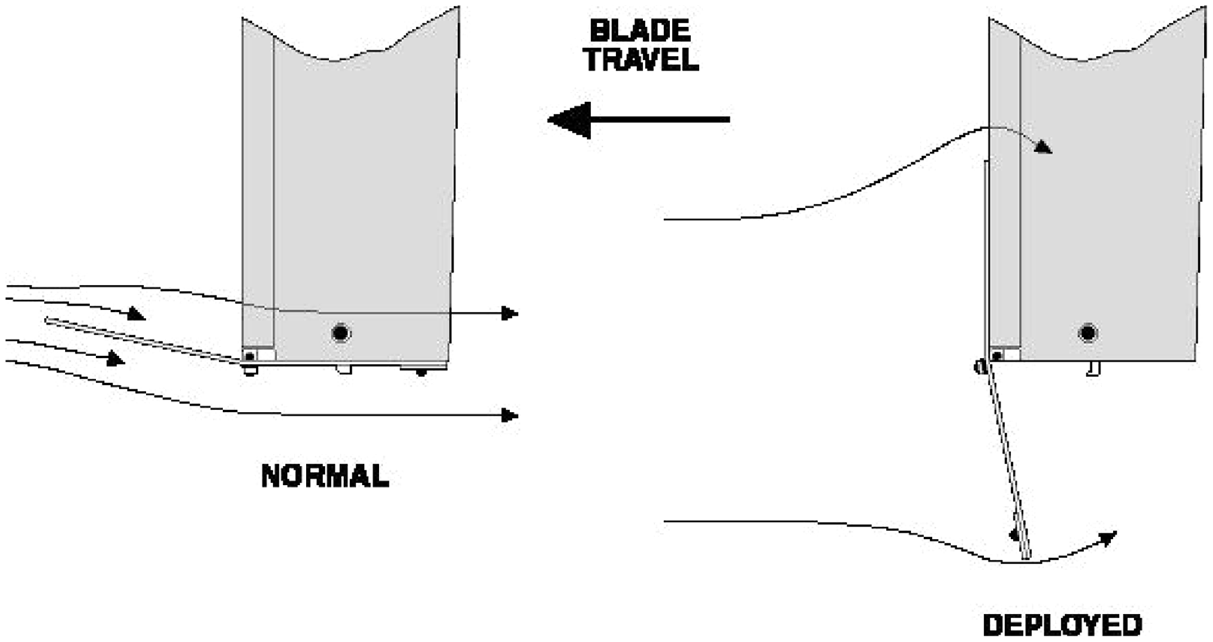
Fortunately, Jørgensen, Stiesdal, and Grove-Nielsen didn’t have far to look for a way to protect the rotor in overspeed. Juul had use pitchable blade tips on his Gedser mill and it was still standing. While Juul had used hydraulics to pitch the blades on his much larger turbine, the more practical choice on the smaller turbines was a spring-loaded system that was activated centrifugally. In normal operation the spring retained the blade tip in its operating position. When rotor speed increased beyond a certain threshold, centrifugal force threw the blade tip out along a grooved shaft that turned the tip 90° to the direction of motion. They quickly adopted this design.
Grove-Nielsen and Økær then began building blades with the automatic-acting blade tip. By the winter of 1978, he was supplying replacement blades with the new pitchable blade tip, including a set to Jørgensen and Stiesdal at Herborg Vindkraft (see Figure 17). It was the self-acting, pitchable blade tips and the Hütter flange that more than anything else contributed to the durability of Danish wind turbines.
Pitchable blade tips. Danish wind turbines, like the thousands installed in California during the early 1980s, used centrifugally activated blade tips to passively protect the rotor from overspeed. Later versions actively pitched the blades to stop the rotor under normal operation. The blades shown here are a static sculpture at the Folkecenter for Renewable Energy in Denmark. The tip of the blade on the right is in the deployed position. Fail-safe, pitchable blade tips may have been the single most important technological factor in the success of Danish wind turbine designs and, ultimately, the development of the modern wind industry.
Herborg Vindkraft and Vestas
Armed with fail-safe overspeed protection, Jørgensen decided to go into production in early 1979 with his and Stiesdal’s design marketed as the Herborg Vindkraft or HVK (Dykes, 2013; Stiesdal, 2013). Like others of the period, their HVK-10 used off-the-shelf components. They attached Økær’ 5-m blades to a distinctive welded hub and mounted the rotor assembly directly on a Hansen gearbox. The transmission drove two induction generators: one for low wind speeds, the second, much larger 22-kW generator for high wind speeds. The HVK turbine also featured a prominent spinner or nose cone and dual work platforms. Though they sold a few units, the firm didn’t prosper.
HVK delivered one HVK-10 turbine with a 30 kW generator to Vestas, a manufacturer of farm equipment and truck cranes in the fall of 1979. Eventually, HVK sold Vestas the rights to their design. HVK then developed a larger version for Vestas designed to use Økær’s new 7.5 m blades. They installed the HVK-Vestas’ V15 in the spring of 1980 at Vestas’ plant in Lem on Denmark’s windy west coast (see Figure 18).
Vestas wind turbine and Økær blades. Background. An HVK wind turbine in Vestas livery at the Vestas plant in Lem. Vestas bought the turbine and design from HVK before launching its successful line of 15-m diameter wind turbines. Foreground. Økær 7.5-m blades with pitchable blade tips developed by pioneering Danish blade designer Erik Grove-Nielsen. Note the “Hütter flange” that made it all work. 1980.
Vestas substantially redesigned the HVK-Vestas turbine in 1981. They extended the nacelle’s bed plate, moved the gearbox rearward, used a long mainshaft supported on two large pillow-block bearings and placed the disk brake on the low-speed shaft. They retained the hub, the work platforms, and the large conical spinner of the HVK design, but housed everything beneath a distinctive fiberglass cover. The Vestas V15, for its 15-m diameter rotor, was born. It became one of the most successful wind turbines of its era. Vestas sold thousands of this model and later variants—most are still operating nearly four decades later.
Stiesdal and Bonus
With the sale of HVK’s design to Vestas, Stiesdal moved on to university (Stiesdal, 2013). Meanwhile, he continued as a consultant to Vestas, working on later Vestas designs including their first variable-pitch rotor, the V23 (Karnøe and Garud, 2012).
Following a failed attempt to buy Nordtank, another Danish manufacturer of wind turbines, Danregn Vindkraft, began building machines of their own design in 1980. In 1983, Danregn, formerly a manufacturer of irrigation equipment—hence the name (Danish rain), began trading under the name of Bonus.
Because they used the same blades as others, Bonus went through the same development cycle as everyone else: 22 kW, and then 30 kW. They installed their first 55 kW model in 1981 near the Folkecenter for Renewable Energy in windy northwest Jutland (see Figure 19).
Bonus 55 kW. First Bonus (Danregn Vindkraft) 55 kW wind turbine. Installed in 1981 near the Folkecenter for Renewable Energy in northwest Jutland, the turbine was the forerunner of hundreds of such turbines installed in California in the mid 1980s. Like Vestas’ V-15, this Bonus turbine used Økær’s 7.5-m (25-ft) blades. In 2004, Bonus was absorbed by Siemens. On the right, Bonus 55 kW drive train. Note the dual generators and large pillow-block main bearing and welded hub. The drive train is part of the Folkecenter for Renewable Energy’s collection of historic Danish wind turbines and components. (Preben Maegaard).
Bonus, like Vestas, opted for putting the brake on the mainshaft. This required a larger and more expensive disk brake than when mounted on the high-speed shaft of the gearbox. However, this arrangement avoided passing braking torque through the gearbox to stop the rotor. This improved reliability and longevity and later served to distinguish the more rugged and durable designs of Vestas and Bonus from other Danish manufacturers, such as Nordtank.
Nordtank, ironically a former manufacturer of tank trucks design to carry liquids such as oil and gasoline, were building similar turbines. Because of their experience fabricating large cylindrical tanks, they pioneered tubular towers. Nordtank’s characteristic stepped or “rocket” tower soon became a feature of the Danish landscape.
In contrast to Vestas and Bonus, Nordtank placed the disk brake on the high-speed side of the gearbox and used sheet metal nacelle covers as did their competitors Micon and other Danish manufacturers.
Though Bonus joined the rush to the budding California market, they never overextended themselves. They were one of the few Danish manufacturers that survived unmarred by bankruptcy when the California market collapsed in 1986. In 1987, Stiesdal finished his studies and joined Bonus. He brought his distinctive design style to Bonus and remained technical director as the company steadily grew, eventually being absorbed by the German electrical conglomerate Siemens (Siemens Wind Power later merged with Spanish wind turbine manufacturer Gamesa to form Siemens Gamesa).
The “Danish concept”
By 1980–1981, blades of the Økær design were being delivered to 20 different manufacturers of wind turbines in Denmark, Germany, the Netherlands, and Belgium (Grove-Nielsen, 2013). Most were building wind turbines quite similar to one another. Development of wind energy had now passed from the hands of the machinists and activists to those of small and medium-size manufacturers who saw wind energy as a rapidly growing business rather than a political cause.
What was to be labeled the “Danish concept” was in full flower. From a distance, the turbines all looked alike. They used a three-blade rotor upwind of the tower without fantails. The blades all looked alike because of their then common source. To distinguish their products from others, some manufacturers chose distinctive paint schemes. In the field you could identify the different turbines by the color of their pitchable blade tips. Vestas used white tips; Bonus, green; Nordtank, red.
Using standardized components enabled the Danish wind industry to scale up quickly. Instead of building specialized components in house, they could instead rely on what’s called today a supply chain of manufacturers who were selling the same product, such as gearboxes, to many different customers. Component suppliers had already won economies-of-scale by manufacturing products in series to a broadly diversified market. Wind turbines were just one more market to gearbox companies or generator manufacturers.
Meanwhile, the manufacturers were diversifying the one component that was unique to wind turbines—the blades. Following storm-caused failures of Økær’s 7.5 m blades in the winter of 1980–1981, Vestas decided to design and build their own blades in-house. Elsewhere in Denmark, LM Glasfiber, a manufacturer of fiberglass yachts, began building blades for Windmatic, a Riisager derivative. Later in 1981 Økær entered a licensing agreement with Coronet Boats, another manufacturer of fiberglass yachts, to begin producing blades under the AeroStar trade name (Grove-Nielsen, 2013). By the mid-1980s there were three manufacturers of wind turbine blades in Denmark: Vestas, AeroStar, and LM Glasfiber.
Rotor blades were the linchpin of the Danish concept and with industrial manufacture of blades underway; the Danish wind industry was primed for explosive growth.
The California wind rush
The growth of an industry is partly about technology, but also about the market for that technology. The demand for wind energy was due to public policy in response to the international crisis caused by the second oil embargo of 1979 (Asmus, 2001).
In response to this event and to pressure from the business community now building wind turbines, Denmark launched its first incentive program. Slowly, the market began to grow as manufacturers established a foothold. Then the California market opened up in the United States and the stampede was on.
California provided its own tax subsidies on top of subsidies from the federal government, effectively doubling the subsidies for renewable energy available in the state. That alone was insufficient. Concurrently, California had begun measuring the wind across the state and making the information public. Now everyone knew where the wind was, it was in three principal mountain passes. Still, a piece of the puzzle was missing. There was no place to sell wind-generated electricity. The existing utilities controlled the market.
Fortunately, the utilities blundered badly, antagonizing the progressive governor and the state regulatory commission. The utilities were discovered colluding to violate a commission order to develop renewable energy. The California Public Utility Commission heavily fined the utilities and ordered them to provide connections to independent power producers and to offer generators standard contracts with fixed prices for their electricity.
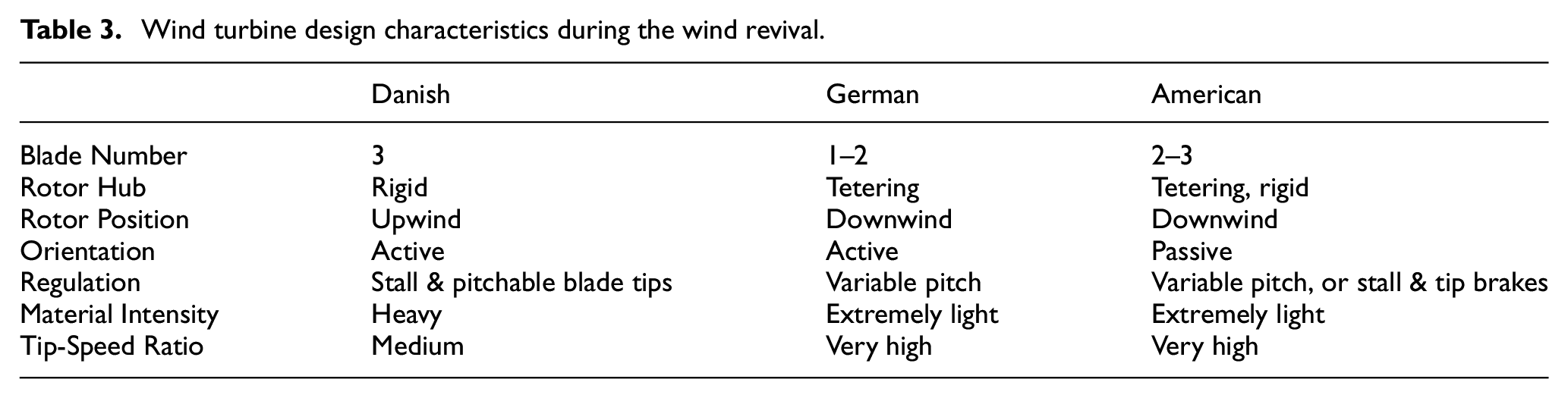
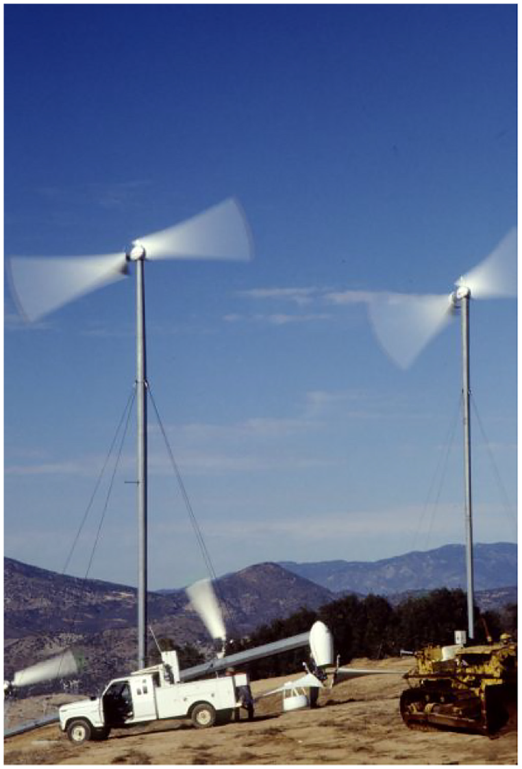
Now, all the pieces of the puzzle were in place. Developers knew where the wind was. They knew how much they would be paid for their electricity. And they had attractive subsidies that would make it economic to produce and sell wind-generated electricity for a handsome profit. The boom was on. Soon a regular train of shipping containers loaded with Danish wind turbines was snaking its way to the United States, drawn by the great California wind rush. From 1980 through the late 1980s there were more than 4600 Danish wind turbines installed in California out of nearly 11,000 wind turbines in the state. For the differences between the Danish and American turbines, see Table 3.
Wind turbine design characteristics during the wind revival.
It was a heady time. The stories of that period now fill books on wind energy. How did various technologies fare in the blistering winds of California’s mountain passes?
Downwind dominant
California became a battleground between two fundamentally different approaches to wind turbine design. While Danes initially fell under the “downwind is modern” spell, the activists and the machinists building wind turbines soon learned that Danish tradition led them to upwind turbines like that at Gedser. American designers of medium-size turbines in the early 1980s had no Gedser mill to turn to for inspiration and remained in thrall of Hütter’s downwind turbines to the end.
Many American-designed turbines of the period exhibited most of the characteristics we associate with Hütter’s design philosophy. Several, such as the Carter and ESI turbines, used downwind, two-blade, teetered rotors operating at fairly high tip-speed ratios as found on Hütter’s StGW-34 turbine (see Figure 20). Others, such as Enertech, Storm Master, and US Windpower opted for three-blade, rigid downwind rotors. Most used integrated drive trains, as had Hütter, and most placed the brake on the high-speed side of the gearbox. Storm Master, Enertech, and ESI even placed the brake behind rather than in front of the generator, creating even more paths for failure. And similar to Hütter, many of the designers came from the aerospace community either directly or indirectly. Jay Carter, Jr. for example, came from Bell helicopter.
Carter 25. Developed by the father and son team of Jay Carter, Jr. and Jay Cater, Sr., the Carter design grew out of the helicopter industry. The nominally 10-m diameter lightweight, teetered rotor was oriented passively downwind of the tower to drive a 25-kW induction generator. The main spar incorporated a filament winding technology developed for Polaris missile casings. The turbine, created independently of the US wind development program, was introduced in 1979. Downwind two-blade designs such as this generated a characteristic “whop-whop” that annoyed neighbors near Palm Springs, California. Circa 1985.
The difference in design philosophy between the Danes and the Americans was apparent to any observer in California during the early 1980s. Danish wind turbines appeared far more massive than the US machines: the Danish blades were thicker and their nacelles bulkier than those on the US-designed turbines. Danish turbines operated at lower tip-speed ratios than the US designs—they spun at slower speeds. All in all the Danish designs projected a sense of solidity and durability missing from the US turbines of the period.
Lightweights in a heavyweight environment
The difference in appearance betrays an underlying difference in design. First-generation European wind turbines had a much higher specific mass in kg/m2 than American wind turbines. That is, there was more mass in the nacelle and rotor of Danish turbines relative to the area swept by their rotors than in American designs.
Few wind turbines epitomize the American lightweight design philosophy better than those designed by the Carter family. They built two models, a 25 kW and a larger turbine variously rated between 250 and 300 kW. Both turbines used a flexible downwind, teetered rotor. The Carter 25 had a specific mass of less than 5 kg/m2, and the larger model was not much better at slightly more than 7 kg/m2.
Compare these designs with Bonus’ 15-m diameter turbine and Vestas’ V17, a 17-m diameter machine. The Danish turbines contained twice the specific mass of most US-built turbines and three times more than the Carter and Storm Master turbines. In the demanding environment of California’s wind farms, specific mass became a surrogate for reliability and durability.
Other turbines characterizing lightweight designs of the early 1980s include Storm Master, Windtech, and ESI. ESI was a commercial spin-off from the US wind R&D program. The ESI turbines were distinctive for their fairly large diameter (comparable to that of Danish turbines), the high speed of their rotors, and the tip brake at the end of each blade. The tip brakes, or flaps, were intended to protect the turbine during high wind emergencies. The design used two fixed-pitch, wood-epoxy blades downwind of its hinged, lattice tower. Two versions were introduced. Nearly 700 of the ESI-54 (16.4-m), and 50 of the ESI-80 (24-m) were eventually installed in California (see Figure 21).
ESI-80. Another US-built series that followed Hütter’s design philosophy were the ESI-54 and the later ESI-80 shown here. The ESI turbines also used a downwind, two-blade, teetered rotor driving an induction generator through an integrated gearbox. The brake is mounted on the back-end of the generator (far left). ESI used tip-brakes like those on the Isle of Man turbine, not pitchable-blade tips. The high rotor speed in combination with the downwind design and tip brakes was notoriously noisy. The ESI-80 used an 24-m rotor made up of laminated wood blades coupled to a 250-kW generator. Circa mid to late1990s.
Whereas, Danish manufacturers were, for the most part, already established and accustomed to building heavy-duty products for a demanding rural clientele, US manufacturers were typically small with little or no manufacturing experience. US firms were also undercapitalized and had no staying power. However, there was one exception: US Windpower.
US windpower
Rebranded in the 1990s as Kenetech, US Windpower (USW) grew out of a successful marriage between the financial and aerospace community around Boston. They built the first wind farm in the United States when they installed 30 prototype 30-kW downwind turbines on Crotched Mountain, New Hampshire in 1980 (Wikipedia, n.d.). Though the turbines were not successful, the project established the investment vehicle for rapid growth in the hothouse atmosphere created by California’s lucrative market.
The company rolled out its first California wind farm in 1981 with its 56-50, a 56-ft (17-me) diameter, three-blade, downwind rotor with a 50 kW rating. In 1985 USW was operating 600 of this model alone. They also introduced a redesigned, and upgraded version with a 100 kW rating (Figure 22). By the end of 1986, USW had installed 2700 wind turbines, more than any other manufacturer.
US Windpower 56–100. One of the most successful of the US-designs from the 1980s, US Windpower’s 56 to 100 used a three-blade, variable pitch rotor, passively oriented downwind of the characteristic three-legged tower. Some 4000 of these 100-kW turbines were at one time operating in California.
The recipe for USW’s success was its ability to raise large amounts of capital quickly, and its vertical integration. It both manufactured the turbine and developed its own wind farms. The company’s design was more complex than others of the day. It used a more complex hub that allowed full-span pitch control, something that wouldn’t be seen on most wind turbines until the late 1990s.
By the time the company collapsed in the 1996—a victim of its own hubris—USW was operating more than 4000 wind turbines in California. Unquestionably, USW’s turbines were the most successful of US-designed turbines of the era. Though most were still in service in 2014, plans to remove the turbines and replace them with a fewer number of much larger, modern wind turbines were finally being implemented in the early 2020s.
Enertech’s E44
Though US Windpower installed more wind turbines in California than any other company, some argue that a small New England company, Enertech, designed a more long-lasting configuration. Beginning in the mid-1970s, Enertech introduced a 1500-W, three-blade, downwind turbine. In the United States it was innovative for the time, because it used an induction or asynchronous generator and could be directly connected to the grid. Initially, the stall-regulated rotor had no overspeed protection. As in Denmark, the company learned the hard way that stall regulation was simply not enough. The turbine was later redesigned with tip brakes (see Figure 23) and repackaged as the Enertech 1800.
Tip brake. Enertech popularized the use of tip brakes for overspeed protection on downwind, induction wind machines in the late 1970s and early 1980s. Tip brakes were troublesome, noisy, and robbed power. Modern versions may be less problematic. The Enertech E44, shown here, was the model for subsequent designs that used electrically released and reclosable tip brakes such as the Atlantic Orient 15/50 in the late 1990s. None are currently manufactured.
In the early 1980s, Enertech introduced a much larger turbine comparable in size to Danish machines of the time. Enertech’s E44, a 44-ft (13.4-m) diameter downwind turbine, was intended for small commercial and rural applications. The US Department of Agriculture (USDA) installed a 25-kW version at its experiment station west of Amarillo, Texas in 1982. USDA’s unit went through several iterations and remained in service for most of two decades. Enertech’s focus shifted once the California market became apparent.
Like ESI, Enertech used specially-designed wood epoxy blades. Unlike generic Danish blades of the time, the Gougeon blades were designed specifically for each turbine. They were not interchangeable. Nevertheless, the blades were the turbine’s most durable component.
By the end of the California wind rush in the mid-1980s, Enertech had sold more than 500 wind turbines to wind farms in the state’s three windy passes. After the market collapsed with the expiration of the federal tax subsidies, Enertech, ESI, and most US manufacturers collapsed as well (California Energy Commission, 1986).
US DOE launched a program during the late 1990s intended to spur a revival of US wind turbine manufacturing by resurrecting the E44 design, itself a derivative of an earlier DOE program, but in the absence of a market doomed them to failure.
Mehrkam
The tragic tale of Terry Mehrkam illustrates the limits to “fly-by-the-seat-of-your-pants” wind turbine design and manufacturing when the necessary skills are lacking. At the same time Riisager was building his turbines in Denmark, Mehrkam was experimenting with wind in his backyard in central Pennsylvania. Mehrkam represented the home-built or craft tradition in the United States much as his counterpart, Riisager, represented the Danish craft tradition. However, their skills were not comparable. Mehrkam was far less skilled or had far less access to others with the skills he lacked than Riisager, the carpenter, or the other Danish “blacksmiths,” that is, professional machinists then building wind turbines.
Additionally, Mehrkham had no wind energy tradition to fall back on. Danes were steeped in wind energy. Mehrkam was improvising and leapt to a wind turbine that was far too big for his skills. He began building a 40-ft (12-m) diameter, four-blade, downwind turbine. Like the early Danish turbines, his stall-regulated rotor had no overspeed control. Unlike the Danes who learned the hard way that overspeed controls were essential, Mehrkam didn’t adapt his design after he began to encounter serious overspeed incidents. His lack of skill and his ambition—or his desperation—eventually cost him his life. While trying to stop a runaway turbine without adequate fall protection, he fell off the turbine and was struck by a blade (Mehrkam, n.d.).
Wind energy and the aerospace arts
The abject failure of the aerospace industry and the national wind development programs that relied on them in the 1970s and 1980s was due to a fundamental misinterpretation. Wind turbines are not airplanes. They were never meant to fly.
Only in superficial ways do wind turbines resemble aircraft. Wind turbines are power plants. They must produce cost-effective electricity. To do so they must perform like other power plant machinery—they must work reliably over long periods with little maintenance. Whereas a wind turbine must operate many hours on only a few hours of service, an aircraft flies only a few hours relative to many hours of skilled maintenance. For example, an airline may spend 5.5 person-hours of maintenance on a relatively low-maintenance, short-haul jet for every 1 hour in the air. Wind turbines, on the other hand, must operate months on end—trouble free—if they are to compete with fossil fuels and nuclear power.
The approach by Hütter and his devotees grew out of the design principles embodied in aeronautical engineering under the assumption (an incorrect one, as it turns out) that aerospace was the industrial sector most capable of building wind turbines. After all, Hütter knew sail planes well. He designed sailplanes before he designed wind turbines.
While US, German and Swedish engineers were building fighter jets, the Danes were building farm machinery. Fortunately for the future of wind energy, Denmark had no aerospace industry. Had Denmark an aircraft industry, it is probable that its wind turbines would have failed in the same manner as those of their German, Swedish and US competitors from an over-reliance on aerospace technology.
Peter Karnøe, a Danish researcher specializing in how technology develops, suggests that success requires the accumulation of knowledge from R&D and—importantly—from field experience. In Denmark, this required blending the values of the Danish craft tradition with the prosaic research needs of fledgling manufacturers aided by Denmark’s Risø national laboratory. As the repository of scientific and technical knowledge, Risø had an important role to play, especially later in testing wind turbines (Karnøe and Garud, 2012).
The Danish industry, says Karnøe, was not handicapped by sophisticated knowledge of aerodynamics. Danes took the lead, he says, by pursuing a bottom-up strategy, because experimenters and small companies had no other choice. Relevant new technological knowledge was acquired by solving problems specific to the open architecture of the “Danish” design.
There was no “ivory tower hierarchy” in the Danish wind industry because of its roots in farm machinery manufacturing, where empirical and hands-on knowledge were highly valued. Danish designers relied on simple, pragmatic principles. They used their intuitive or “seat-of-the-pants” knowledge about materials to reach a first-order approximation of how a wind turbine should be built.
Danes also had the Gedser mill as a model. Like La Cour before him, Juul had developed some simple “rules of thumb” for designing a wind turbine based on his experience with his machine at Gedser.
Though learning through failure was the most effective way to gather technological knowledge in the 1980s, it will no longer be as helpful, warns Karnøe, because the machines have grown much larger and the costs of mistakes have risen proportionally. Danish manufacturers have since acquired sophisticated technology and have become more analytical in wind turbine design than they were during the formative years. Today’s wind turbines are far most cost-effective and reliable as a result.
Modern wind turbines have reached the state of technological sophistication and maturity that the aerospace community in the United States and Germany tried to develop in the 1970s and 1980s. However, success was achieved from the bottom up, not from the top down and it owes its existence to wind pioneers outside the aerospace and electric utility industry. Many of these pioneers were openly critical of their country’s official wind programs and the utilities that were selected to implement them.
Beginning of the modern era
The history of wind energy is often portrayed as a continuous development from one technology to the next. In reality, the history of modern wind energy is one of fits and starts, technological dead ends, and the abrupt collapse of markets as the temporary abundance of fossil fuels, petroleum specifically, lures leaders with promises of inexpensive abundance.
Several times in the past, notably during both world wars and then again in the 1960s, wind was on the verge of breaking out of its niche to become a major source of electric power. Alas, it was not to be until the oil embargoes of the 1970s and the threat of shortages ever since has led to enduring growth.
In the end, it was a group of students, their teachers, and the many volunteers at Tvind that created the initial blade design incorporating Hütter’s flange. But it took entrepreneurial wind activists and Denmark’s small manufacturers to commercialize the technology through standardized component parts that led progressively to the today’s booming worldwide wind industry. The world owes these Danish pioneers a debt of gratitude for the birth of modern wind energy and the spark that started the renewable revolution now sweeping the globe.
Denmark decided not to develop nuclear power in 1985, a year before the world first heard of Chernobyl. Sweden closed the first reactor at Barsebäck, the nuclear power station placed 20 km from the Danish capital to Denmark’s dismay, in 1999. They closed the second reactor in 2005. Meanwhile, Tvind’s turbine continues to spin, generating clean electricity.
Instead of nuclear, Denmark chose to develop wind energy. They’ve never looked back. In 2020, Denmark produced nearly 60% of its electricity generation from wind energy and nearly 50% of total electricity consumption, fast approaching what Johannes Juul in the 1950s was convinced Denmark was capable of (Danish Energy Agency, 2021).
Comparison: Then and now
One metric for measuring our progress over the past century is the amount of energy a modern wind turbine extracts from the wind, relative to early wind turbines. Modern wind turbines, whether household-size machines or much larger commercial-scale turbines, are typically 10 times more powerful than their forebears for the same size (see Table 4).
Comparison of modern wind turbines with traditional windmills.
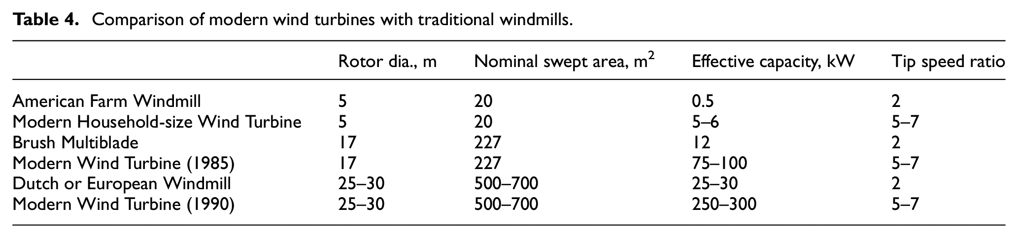
Modern airfoils are derived from a 100 years of development in aviation and aeronautical engineering. To use these airfoils most effectively, modern wind turbines must operate at higher rotor speeds than traditional windmills. This is reflected in the difference between the tip-speed ratio of the two technologies.
The tip-speed ratio is the speed of the tip of the blade as it moves through the air relative to that of the speed of the wind across the ground. The tip-speed ratio is not a constant; it varies with rotor speed and wind speed. Consequently, the tip-speed ratio is typically specified for a particular wind speed (usually one where the turbine’s rated power has been reached). It is one of the most useful parameters in describing a wind turbine (Twidell and Weir, 2005).
Modern wind turbines are “fast runners”. They use “high-speed” rotors relative to traditional windmills. The development of modern wind turbines has been in part a search for the right combination of airfoils, blades, rotors, and speeds at which they should operate. Today most wind turbines deliver their rated power at a tip-speed ratio of between five and seven.
Commercial-scale wind turbines have grown steadily in size from modest beginnings in the late 1970s and early 1980s. As manufacturers refined the technology, the turbines doubled in size every few years as measured by their rotor swept area. Large wind turbines in the mid-2010s were typically 50 times the size of the commercial turbines installed in the early 1980s. Today’s wind turbines sweep 100 times more area of the wind stream than those of the early 1980s (see Table 5).
Technology development of commercial wind turbines.
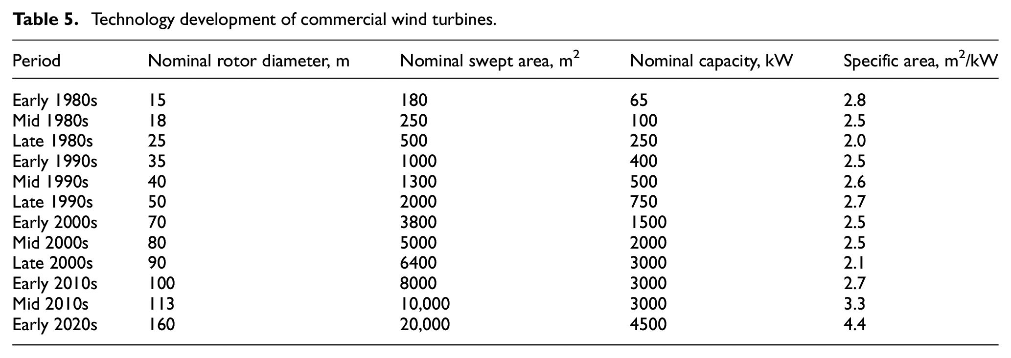
Rated power generally kept pace with increases in swept area until the mid-2010s when a design revolution swept the industry. Suddenly, rated power no longer increased as wind turbines increased in size. The relative swept area, rotor swept area relative to power (m2/kW), began to increase faster than rated capacity as the industry moved to less windy interior sites. This was a subtle but revolutionary movement that had long been stalled by the rush to the windiest locales.
The silent revolution
There is a technological revolution underway today in wind turbine design. It doesn’t garner headlines or breathless prose. It is, as French renewable energy analyst Chabot calls it, “a silent revolution” (Chabot, 2013a, 2013b; de Vries, 2013; Gipe, 2006, 2013, 2017; Hirth and Müller, 2016; Molly, 2011).
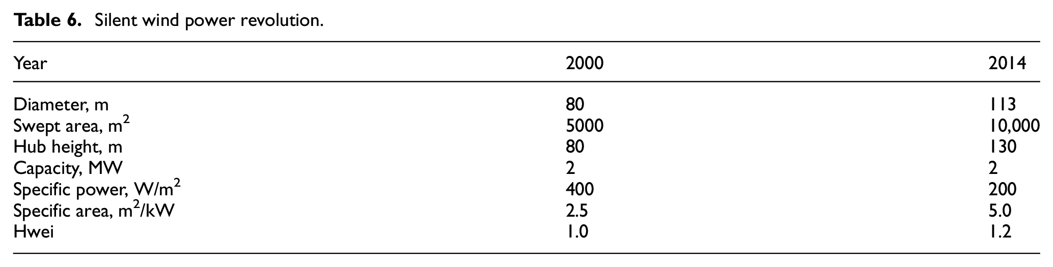
This revolution is being led by large diameter wind turbines with relatively low generator ratings. These wind turbines look exactly like the wind turbines that they supersede with the exception that maybe the blades are a little longer, a little more slender, and a little more flexible than previously. This is the technology that makes high penetration of wind energy more likely than ever before because it reduces the need for storage and new high-voltage transmission capacity. These are wind turbines designed for low and moderate wind regimes. We’ve known how to do this since Hütter. What’s new is that manufacturers are now delivering products with nearly double the specific area of turbines designed for windier sites just a few years ago (see Table 6).
Silent wind power revolution.
From the early to mid-2000s, Nordex was one of the pioneers in large diameter turbines with relatively low power ratings. For example, Nordex offered its N80 rated at 2.5 MW while it was also offering its N90 rated at 2.3 MW. Again, the N90 is the larger, more powerful wind turbine. The N90 sweeps ∼25% more of the wind stream than the N80, and, consequently, would generate considerably more electricity—even though it has a lower generator rating than the N80.
GE’s 1.5 MW platform was introduced in the early 2000s and has been on the market for more than a decade since. It began with a 71-m diameter rotor and evolved to the 1.5 MW SL, a 77-m diameter wind turbine. Though both turbines used the same generator rating the SL used a rotor that intercepted 18% more of the wind stream. Consequently, the 77-m turbine would generate more electricity even though it had the same generator rating as the earlier model. In the mid-2000s GE was installing a 1.6 MW wind turbine with a 100-m diameter rotor (see Figure 24).
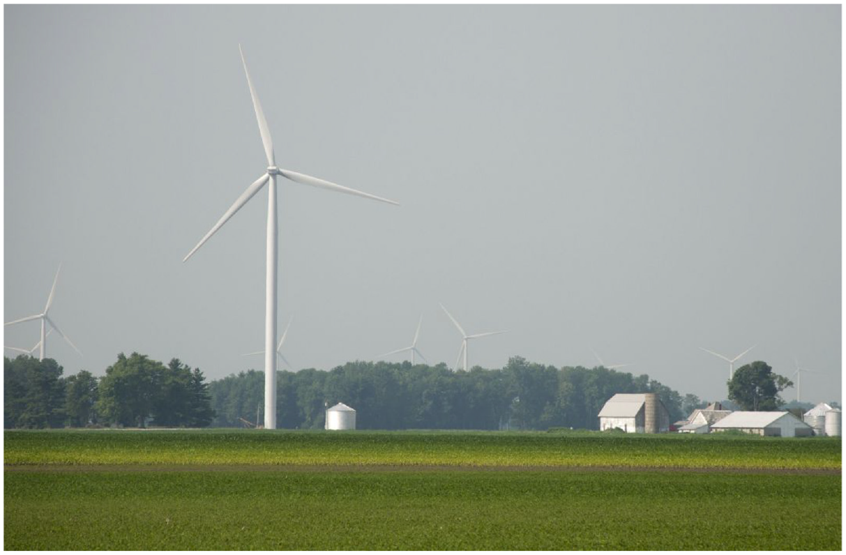
GE 1.6 MW. German utility E.ON installed 125 of GE’s 100-m diameter turbines in the first phase of its Wildcat wind farm near Elwood, Indiana. With a specific area of 4.9 m2/kW—about twice that of wind turbines manufactured only a decade before—GE’s 1.6 MW wind turbine has been designed for areas with low to moderate wind speeds. 2013.
Manufacturers are now offering very large diameter wind turbines with relatively low power ratings that are designed for low to moderate wind speed sites. For example, a wind turbine that would have been rated 3 MW or more a few years ago is now being offered as a 2 MW turbine, sometimes even less. These wind turbines will generate much more electricity than earlier turbines rated at 2 MW, delivering very high generator performance in terms of capacity factor or full-load hours. In this regard, they’re revolutionary.
Chabot summarizes why this is important.
More generation and higher penetration rates relative to installed capacity,
Expanded opportunities through use of lower-wind sites,
Less opposition to wind as less high-wind, high-value sites are now required,
Less demand on grid operators,
Less demand for new transmission capacity or capacity upgrades, and
Wind turbines with large rotors relative to their generator size will allow easier integration of wind energy into the grid, and allow us to put the wind turbines where the people are, that is, near our cities, towns, and villages.
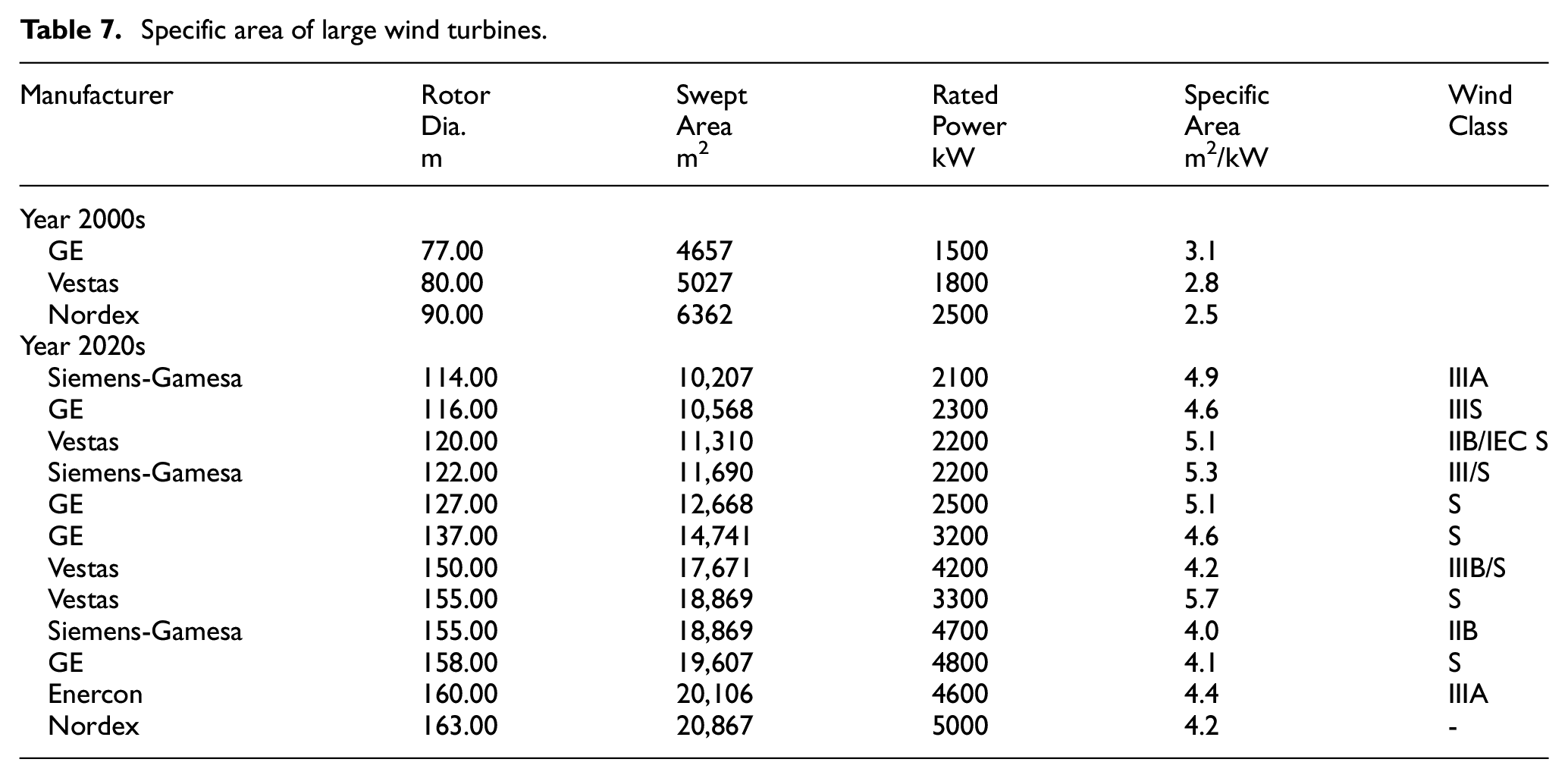
While these wind turbines are, for the most part, no longer on the market they have been replaced by newer models reflecting this trend (see Table 7).
Specific area of large wind turbines.
For many years those who wanted to use wind turbines in lower wind regimes, typically near where people live, were forced to use wind turbines that were designed for high wind sites. While such turbines were adequate for the task they generated very low yields. This was acceptable as long as wind energy was a small part of the generating mix and there was more than sufficient capacity on the wires and electrical infrastructure to absorb peak power on those occasions when it occurred.
All this began to change as more and more of the high-wind sites were developed and the bottlenecks to long-distance transmission of electricity became more problematic.
Like his French colleague Chabot, Quebec engineer Bernard Saulnier believes the new IEC Class III turbines are not only revolutionary because they allow deploying new wind generating capacity in lower wind speed regions, but also because—whether they realize it or not—the manufacturers have declared war on the centralized generation model and the long transmission lines that are an essential part of that model (Saulnier, 2013).
German wind engineer Molly also points out that low specific power-high specific area turbines use the existing network so much more effectively that it drastically reduces the need for storage of a variable resource like wind energy. Thus, argues Molly, we can rethink how best to integrate the high penetration of wind energy into the grid. Incorporating these new wind turbines in the transmission and distribution system will be much more cost-effective than adding expensive storage facilities, or expanding transmission capacity with thicker cables on existing lines, or installing controversial new power lines and their attendant substations (Molly, 2011).
Low specific capacity-high specific area turbines increase the average power they can deliver for a longer period of time, improving both the predictability of wind energy to grid operators, and improving the ability of wind turbines to provide reserve generating capacity for emergencies, such as when a nuclear plant trips offline. And because the difference between average power and rated power is smaller, there is a much reduced need for greater transmission capacity.
French engineer Chabot makes a similar observation; wind turbines with low specific power-high specific area “represent a strategic advantage for the large-scale integration of wind energy” in the electricity system. Much greater amounts of electricity can now be generated with a lower total installed capacity, he says. And this capacity can be placed nearer the centers of consumption than otherwise, reducing the cost of electrical transmission and distribution. This is a huge advantage, says Chabot, for adapting our existing infrastructure, which was built at such a high cost, to the high penetration of renewables that is coming.
Long awaited, high specific area turbines like those anticipated by Hütter are the kind of technology needed to make wind energy an essential low-cost component of supplying 100% of society’s electricity with renewable energy.
Conclusion
Modern wind turbine design for use on land has coalesced around a standard configuration of a large diameter rotor using three blades upwind of the tower with high specific swept area relative to rated generator capacity. It was small-scale Danish manufacturers in the 1970—1980s, skilled at serving an agricultural market that developed products which evolved into the commercial wind turbines of today, and not the governmental-funded wind programs with large-scale prototypes developed by the aerospace industry.
Footnotes
Acknowledgements
The authors would like to thank John Twidell, Etienne Rogier, Matthias Heymann, Mark Haller, and James Manwell for their kind help with providing information on certain historical wind turbines.
Declaration of conflicting interests
The author(s) declared no potential conflicts of interest with respect to the research, authorship, and/or publication of this article.
Funding
The author(s) received no financial support for the research, authorship, and/or publication of this article.