
Abstract
We review the development of wind turbines for generating electricity from the late 19th century to the present, summarizing some key characteristics. We trace the move from two to four blade wind turbines to the three blades common today. We establish that it was not the governmental-funded wind programs with its large-scale prototypes of the 1970–80s that developed into the commercial turbines of today. Instead it was the small-scale Danish wind turbines, developed for an agricultural market, that developed into the commercial turbines of today. And we show that much of what we know today about wind turbine design was known by the 1930s and certainly well known by the late 1950s. This work is divided into two parts: the first part takes up the development from the first electricity producing wind turbines through to the 1960s and a second part on development from the 1970s onward.
Introduction
Wind energy has been used for millennia to sail the seas, grind grain, saw timber, press oil, shred tobacco, and pump water. Windmills mechanically powering machines in the wind-swept lowlands of the Zaan estuary in the Netherlands was a leader in the industrial revolution (De Decker, 2009; Stokhuyzen, 1963; Zaanse schans windmills Amsterdam).
In the late 19th century inventors turned their attention to using the wind for generating electricity. Technological development followed sporadically until the oil crises of the 1970s spurred renewed interest.
Aim of paper
We briefly trace the development of modern wind turbines from the late 19th century to the present in Europe and North America. Much has been written about the history of wind power in both the academic and popular press. Libraries contain entire shelves devoted to books on the history of the Dutch or European windmill, the American water-pumping windmill, and now modern wind turbines.
This work is adapted from two chapters in “Wind Energy for the Rest of Us” by the first author (Gipe, 2016) and summarizes the key characteristics of wind turbine development in tabular form, showing that the technology has converged to a common configuration: Horizontal-axis wind turbines with a three-blade rotor upwind of the tower. We introduce the metric of specific area (m2/kW) as a defining parameter for wind turbines used on land.
By revisiting historical wind turbines and development threads, we will try to shed light on what has developed into the large successful commercial wind turbines of today. We have also expounded on two relatively little-known post World War II wind turbines; one in Germany and one on the Isle of Man. We have also corrected the historical record on the capacity of the Smith-Putnam wind turbine.
This work is divided into two parts: the first part takes up the development from the first electricity producing wind turbines through to the 1960s and a second part on development from the 1970s onward, see (Gipe and Möllerström, in press).
Limitations
We focus only on the development of onshore wind turbines and we focus only on development in Europe and North America. While Vertical-Axis Wind Turbines are mentioned, they are not discussed at length. These are discussed elsewhere (Möllerström et al., 2019). Nor do we discuss the development of wind turbines with only one blade, or ducted wind turbines. Both strategies fall outside the main stream of wind turbine development.
Wind-electric generation: The beginning
The 19th-century was a time when growth in our understanding of electricity was in full flower. Scientific journals filled their pages with the latest discoveries. Storage batteries were being developed in France. Edison and Westinghouse were fighting the “war of the currents” in the United States. Siemens was building electric trams in Great Britain. Central-station power plants were being built using alternating current generators to power lights and motors. Telegraphy was moving rapidly toward telephony.
Late in the century several inventors on both sides of the Atlantic turned their talents to harnessing the wind to generate electricity. Within a few months of each other, the first wind turbines built for generating electricity were installed in Scotland and France. These were soon followed by one in the United States and a few years later by one in Denmark. These inventors were current with the latest scientific developments of the age. None are household names now, though they were all major figures of their day. And with the exception of the work in Denmark, none of their experimentation resulted in any lasting technological development.
James Blyth
In late July of 1887, noted Scottish professor of engineering James Blyth began operating the world’s first electricity generating wind turbine (Price, 2005). He built a conventional four-blade European windmill using cloth sails. The traditional design required turning the turbine into the wind and furling the cloth sails to control rotor speed. Blyth quickly found that it was difficult to control the rotor in the strong winds Scotland is famous for as he couldn’t reef the sails himself. The following year Blyth installed a multiblade farm windmill. He was still dissatisfied. Like a good engineer, Blyth chose to work around his limitations and subsequently in 1891 designed a simple vertical-axis rotor patterned after the recently invented Robinson cup anemometer (see Figure 1). He chose this design because it was inherently self-limiting (see Table 1) and wouldn’t require his constant attention.
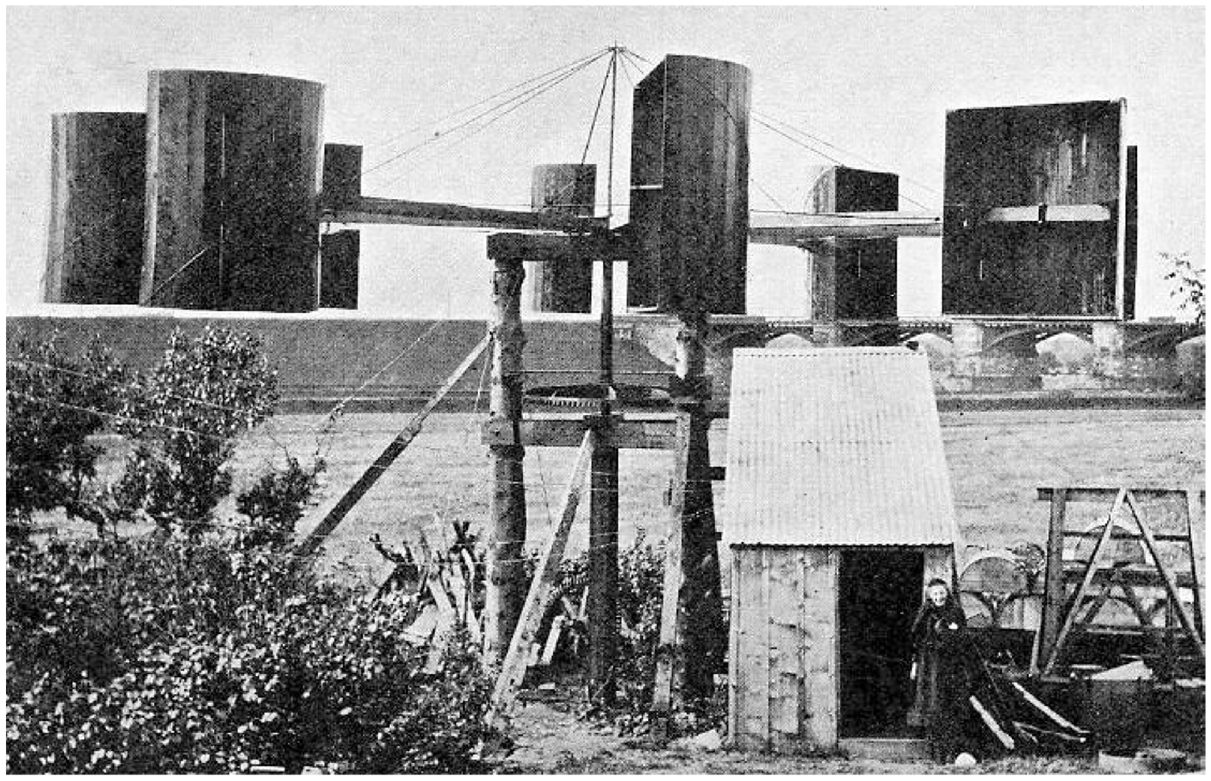
Blyth’s 1891 VAWT. James Blyth built two wind turbines before he assembled his 1891 Vertical-Axis-Wind-Turbine at his summer home in Marykirk, Scotland. Blyth patterned this version after the recently invented Robinson cup anemometer. Blyth not only built the first wind turbine to generate electricity, he also built the first VAWT. (Wikimedia Commons).
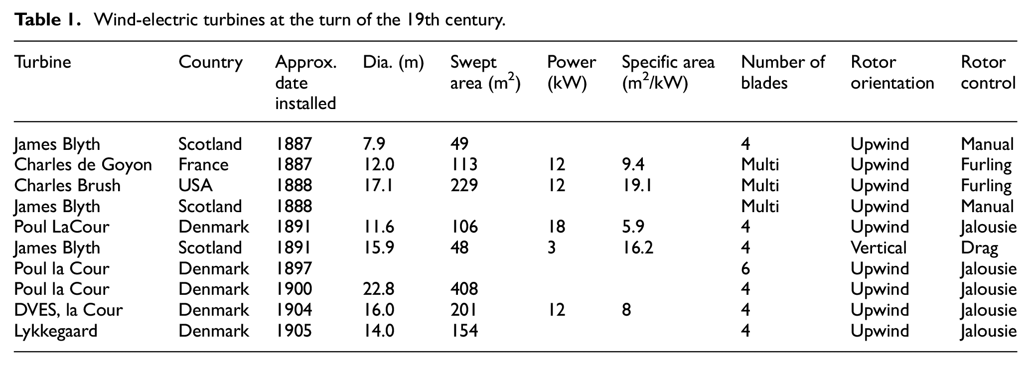
Wind-electric turbines at the turn of the 19th century.
By deliberately choosing a device that became less and less efficient as wind speeds increased, and by keeping his machine within a size he could manage with the materials at hand, Blyth was able to build the world’s first Vertical-Axis Wind Turbine (VAWT) used to generate electricity. He then used it to light his summer home northeast of Edinburgh.
Blyth was prescient in many ways. While experimenting with the American multiblade windmill design, he envisioned mounting the dynamo on the wind turbine itself instead of on the ground. In this way, the dynamo could be driven directly by the wind shaft without bevel gearing. It would be at least two decades before experimenters placed the generator atop the tower in this manner (Blyth, 1892). He also used the power from these early experiments to drive a lathe “to make a light form of carriage to be driven by the same [batteries], so that I am in hope of having some day a drive by means of stored wind energy” (Blyth, 1892).
John Twidell, himself a respected British wind pioneer, notes Blyth made a prescient observation based on his personal experience that “any fool can make a wind turbine go round to generate electricity, but the challenge is to make one that can be left unattended without over-speeding to destruction.” 1 All wind turbine design could be boiled down to that one observation—essentially the same lesson that Danish wind turbine designers learned the hard way nearly 100 years later.
Blyth (1892) laid down three rules for harnessing the wind successfully, and they remain true to this day.
It must be always be ready to go.
It must go without attendance for lengthened periods.
It must go through the wildest gale and be able to take full advantage of it.
Charles de Goyon
Across the Channel, French noble Charles de Goyon, the Duc de Feltre, and his collaborators were turning their attention to the wind as well. De Goyon’s group installed a multiblade farm windmill in early September of 1887 on the coast of France (Rapin and Noël, 2010). De Goyon coupled a 12-m diameter Halladay Standard power mill to two dynamos for charging batteries. At a time when most farm windmills were only 2.4–3 m in diameter, de Goyon had ambitiously chosen a large wind turbine of the size typically used for mechanical power. Like Blyth, who used his wind turbine to charge newly invented batteries, De Goyon used his machine for charging “accumulators” as well (Rogier, 1999).
He subsequently modified the design to power the la Hève lighthouse near the French port of Le Havre for the French government. His efforts mark the first time a wind turbine was used commercially, that is, where the electricity produced would be made for sale to others (Rogier, 1999).
It is noteworthy that de Goyon used a power mill of the kind that was being installed commercially in North America and in Europe at the time. These windmills were successful because they were automatically self-regulating, they would furl the rotor out of the wind automatically in dangerous winds. They didn’t require a miller to furl their sails or point them out of the wind. James Blyth would approve.
Brush Dynamo
Like de Goyon, Charles Brush chose to work with a technology that was then commonplace, the American multiblade windmill (Guarnieri, 2017; Righter, 1996; Shepherd, 1994; Spera, 1994).
In 1888, Brush installed a massive windmill to drive a 12 kW DC dynamo for powering the lights on his estate outside Cleveland, Ohio (see Figure 2). Brush patterned his wind turbine after the water-pumping and power windmills being used across North America’s Great Plains. Even so, his wind turbine was large for the day. It stood atop an 18.3-m tall tower that pivoted with the wind like a traditional post mill common in the lowlands of Europe. The 17-m diameter rotor was twice as large as de Goyon’s (see Figure 3).
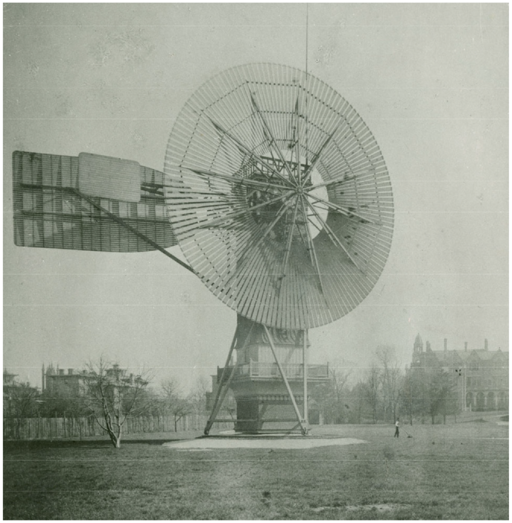
Brush dynamo. Industrialist Charles F. Brush developed the first electricity generating wind turbine in North America for his Cleveland, Ohio estate in 1888. The 17.1 m diameter rotor used 144 wooden slats in a configuration common among water-pumping, farm windmills of the era. The 12 kW wind turbine used a pilot vane to turn the rotor out of the wind. The rotor is furled or out of service in this photo. (Western Reserve Historical Society).
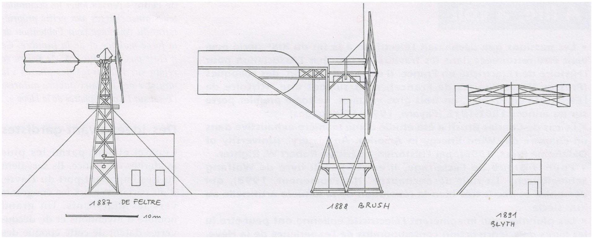
Schematic of early wind-electric generators. Comparison of the size, shape, and orientation of the Duc de Feltre’s wind turbine near La Havre (1887), Charles Brush’s turbine near Cleveland (1888), and James Blyth’s later Vertical-Axis Wind Turbine (1891). Blyth’s machine was substantially smaller than the other two. (Etienne Rogier).
Importantly, Brush’s dynamo was automatically self-regulating in high winds. Like multiblade windmills of the day, it used a pilot vane in the plane of the rotor to furl the rotor toward the tail vane in strong winds. The speed of the wind at which this occurs could be adjusted with weights and the rotor could be manually furled out of the wind as desired.
The Danish Edison
Poul la Cour began experimenting with the wind to generate electricity around the turn of the 19th century (Nielsen, 2010; Nissen et al., 2009). la Cour, known as the “Danish Edison,” was a meteorologist, inventor, and teacher. As a meteorologist, he was familiar with the power of the wind. As an inventor, he rivaled Elisha Gray and Alexander Graham Bell in what today we call telecommunications. And as a teacher he wrote textbooks on mathematics and geometry. But it’s la Cour’s work with wind energy that he’s best remembered and where he made his mark.
La Cour joined the faculty at the folkehøjskole in the village of Askov in central Jutland at a time when coal-fired power stations were first being introduced into Denmark’s major cities. La Cour proposed using Denmark’s abundant wind instead of the country’s limited supply of coal. Thus, it was at Askov that la Cour made history when he installed his first electricity-generating wind turbine in 1891 (see Figure 4). For the next 17 years la Cour continued experimenting with wind energy and, more importantly, conducting scientific experiments on what he termed the “ideal” windmill.
Poul la Cour’s klapsejlsmølle. La Cour’s original 1891 electricity-generating wind turbine used klapsejls, clap-sails, or jalousie shutters. The self-regulating rotor was 11.6 m (38 ft) in diameter and drove an 18 kW dynamo at ground level. The rotor was oriented into the wind with dual fantails. (Poul la Cour Foundation).
The first turbine installed at Askov used cloth sails as widely used on traditional European windmills at the time, but la Cour soon replaced them with klapsejls (clap-sails) or jalousie shutters on a rotor nearly 12 m in diameter. These self-regulating shutters were not original with la Cour, they were fairly common on windmills of the late 19th century. Nor were the dual fantails on la Cour’s turbine unusual for orienting the wind turbine into the wind. They too were found on traditional windmills in Northern Europe. These features were all well known to millwrights of the period. What was unusual was la Cour’s adaptation of the traditional four-blade windmill to generate electricity by transmitting mechanical power to ground level where the spinning shaft drove an 18 kW dynamo.
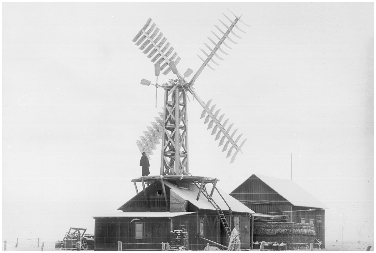
In 1897 la Cour installed a much larger turbine atop his new laboratory. This keglevindfang or “conical wind catcher” was the product of a local millwright and represented the intuitive thinking of the day (see Figure 5). To the uninitiated, the fanciful wind catcher with its six blades where each blades was wider at the tip than at the root, appears like it should be much better at, well, catching the wind than la Cour’s inelegant four-blade rotor. That wasn’t the case and la Cour wanted to know why.
Askov’s conical wind catcher. In 1897, Poul la Cour added a keglevindfang or “conical wind catcher” (left) atop Askov’s new laboratory. (His earlier turbine is in the background.) The wind catcher used an unconventional six-blade rotor developed by a local millwright. The rotor represented the intuitive thinking of the day, but proved unsatisfactory, leading la Cour to his famous wind tunnel experiments on wind turbine rotors. Eventually, the wind catcher rotor was replaced with a more conventional four-blade rotor designed by la Cour. (Poul la Cour Foundation).
This question led la Cour to use one of the world’s first wind tunnels a full decade before Gustave Eiffel built his wind tunnel in Paris at the foot of his famed tower. la Cour’s results upended the thinking of the day, pointing the way for the later work of physicists who would found the then unknown field of aerodynamics. la Cour realized that the conventional wisdom that the sails of a windmill responded to the impulse of particles that hit them didn’t explain why power was greater when he tested rotors with less frontal area (less blade area and fewer blades). He controversially concluded that the four blades of his original turbine were superior to the six on one of his later turbines (Quistgaard, 2009).
What set’s la Cour’s work apart from Brush, Blyth, and de Goyon is that la Cour’s approach built on hard won mill-building experience aided by the knowledge he gained from his wind tunnel measurements. After all, millwrights had been successfully building windmills for hundreds of years.
Millwrights had learned, for example, that four blades were optimum for the materials at hand. la Cour reached the same conclusion from a different direction—through a methodical scientific approach. Millwrights too had come to the same conclusion as Blyth that the rotor needed to be automatically self-limiting, thus the automatic controls on the jalousie shutters.
la Cour’s traditional configuration could also be scaled up to much larger sizes than that using the farm windmill design chosen by de Goyon and Brush. la Cour erected his second turbine, a traditional four-blade rotor 23 m in diameter, atop his laboratory. This experimental turbine was twice the size of that built by Brush, and four times that of de Goyon, both large turbines of their day.
The work of Blyth, Brush, and de Goyon ended with the inventors and their one-off experimentation. In contrast, the results of la Cour’s experimentation lived on after his death. By the time la Cour died in 1908, he had built a rich legacy, including a direct line to the development of modern wind turbines. Unlike other wind turbine experimenters of the period, la Cour’s systematic investigation of what would soon become the field of aerodynamics led inexorably to modern wind turbines.
Several Danish machine shops subsequently began producing wind turbines to la Cour’s design. The most successful was the Lykkegaard Machine Works on the island of Funen. They began building wind turbines in la Cour’s time and continued well into the 1950s. These wind turbines were typically 14 m in diameter driving 6 kW DC dynamos.
Technological dead ends
French historian Etienne Rogier argues that de Goyon’s experimentation was potentially more important to the development of wind energy than that of either Brush or Blyth. De Goyon used a widely available industrial product of his day rather than a one-off experimental device, says Rogier. If de Goyon had been successful, there was a ready platform of manufacturers who could put the new machine into industrial production (Rogier, 1999).
Not surprisingly, there were many subsequent attempts to commercialize the path chosen by de Goyon well into the 1920s in both North America and Europe. Rogier notes that two French manufacturers, Chêne and Les Etablissements Cyclone, were particularly active in promoting the concept for providing electricity to wealthy clients on their country estates.
There were also commercial attempts in the United States in 1893 to adapt water-pumping windmills and further experimentation with vertical-axis wind turbines in Britain in the mid-1890s (Righter, 1996).
The requirements for generating electricity effectively are far different than those for pumping water or providing mechanical power and the approach of both Brush and de Goyon confirmed that the low-speed, multiblade rotor was a technological dead end for generating electricity.
The interwar years
The Great War brought rapid advances in aeronautical engineering following the pioneering work of British, French, and German physicists. Unlike la Cour’s klapseijler wind turbine design that dominated the pre-war period, post war development soon adopted the airfoils demonstrated so dramatically during the war and applied them to wind turbines (See Table 2).
Wind-electric turbines during the interwar years.
First AC interconnected wind turbine
Prior to the war, most rural electrical systems in Denmark used direct current (DC) to serve small areas. Early Danish wind turbines patterned after la Cour’s design were often used to supplement these networks.
However, during the war, the utility serving the area north of Copenhagen introduced alternating current (AC). In 1919 the utility installed an Agricco wind turbine at Buddinge and connected it to its lines (Nissen et al., 2009). This is the first known example of a wind turbine interconnected on an AC network worldwide (see Figure 6).
First Interconnected Wind Turbine. The Agricco was not only one of the first wind turbines to use true airfoils, but also the first wind turbine connected to an AC network. In 1919 a 12.5 m diameter, Agricco driving a 40 kW asynchronous generator fed AC electricity into the lines of Nordsjællands Elektricitets og Sporvejs Aktieselskab (NESA) at Buddinge north of Copenhagen. Built from 1919 to 1925, the wind turbine use five or six variable-pitch blades upwind of the tower. (The Danish Museum of Energy).
The 40-kW Agricco was an odd mix of new and old, but surprisingly advanced for its day. The turbine used true airfoils in the blades for the first time, but it used five or six blades instead of the four blades recommend by la Cour. The rotor used struts and stays to brace the blades, much like later Danish wind turbines. And the Agricco used fantails to orient the rotor into the wind. Nevertheless, tests in the early 1920s found that the Agricco wind turbine was twice as efficient as la Cour’s design (Thorndahl, 2009).
To produce utility-compatible AC, the Agricco employed an asynchronous or induction generator for the first time. This choice proved significant and would later influence other wind turbine designers in Germany and France. Compared to using a synchronous generator, using the cheaper induction generator greatly simplified the design and its interconnection with the grid.
Unfortunately, there was little demand for wind energy when the war came to a close and Agricco reached a dead end. Danish historians describe the Agricco as the right windmill at the wrong time (Thorndahl, 2009).
La Cour’s design continued to live on into the 1920s and 1930s in the form of the Lykkegaard klapsejlsmølle. No other wind turbine was used as extensively in Denmark for power generation. By the mid-1930s, there were 40 Lykkegaard machines at DC power stations in Denmark.
Wind meets aviation
By the mid-1920s a veritable who’s who of the great names in physics, aviation, fluid dynamics, and the new field of aerodynamics were designing, testing, and experimenting with wind energy. In France engineer Louis Constantin began experimenting with wind power in the early 1920s. By 1926 he had constructed a wind turbine using a two-blade upwind rotor 8 m in diameter in France’s Massif Centrale. This was the first of several prototypes Constantin would build in central and southern France. According to French historian Rogier, Constantin was one of the founders of modern, high-speed rotors for wind turbines (Rogier, 1999).
Constantin anticipated modern wind power plants where multiple wind turbines would be used together in batteries or arrays to produce electricity for the grid. Like la Cour a decade earlier, Constantin recognized the importance of a scientific and commercial associations to develop the technology and formed Energie Eolienne, a society to promote wind energy that lasted from 1929 to 1936.
Meanwhile, French engineer Georges Darrieus was installing prototype two-blade turbines at a test field outside Paris and pondering, like Blyth before him, wind turbines that rotated about a vertical axis (Möllerström et al., 2019). 2
Darrieus
Largely forgotten today, Georges Jean Marie Darrieus was one of France’s great engineers. While he is mostly known in the English-speaking world for his patent on vertical-axis wind turbines (VAWTs) in 1925, he was a prolific inventor in a number of fields from ballistics to turbo-alternators.
Darrieus picked up where his contemporary Constantin left off. Not long after he filed his famous patent, Darrieus installed several horizontal-axis wind turbines in the late 1920s for his employer Compagnie Electro-Mécanique (CEM) at le Bourget outside Paris.
Relatively novel for his day, his prototypes used passive yaw of a downwind rotor to orient the turbine in response to the wind—a feature that would fascinate American designers in the 1970s (Lacroix, 1929).
In 1927, Darrieus installed his first model a four-blade 8 m diameter rotor powering a DC dynamo at the top of a wooden tower. Later he installed another version on a metal truss tower. Both employed a brake on the high-speed shaft to stop the turbine (Lacroix, 1929).
The wooded blades used a bi-plane construction with the secondary blade partially spanning the first blade. Darrieus produced two variants: one for charging 24-volt batteries for use in lighting; and another for charging 110-volt batteries for lighting and power (Lacroix, 1929) (See Figure 7).
Darrieus Bi-blade prototype. In 1927, Georges Darrieus installed an 8-m diameter, downwind turbine with four bi-blades at Compagnie Electro-Mécanique (CEM) at le Bourget outside Paris. He produced two variants and tested the turbine until 1929. It was theoretically capable of 10 kW at a wind speed of 9 m/s. Today Darrieus is most well known for vertical-axis concept. (Sketch by Etienne Rogier. All rights reserved.).
The turbine was designed to generate 1.8 kW at a wind speed of 6 m/s with rotor speed of 60 rpm. It was theoretically also capable of 10 kW at a wind speed of 9 m/s with the rotor running at 150 rpm (Lacroix, 1929; Rogier, 2000). Testing lasted 2 years at the end of which Darrieus installed a much more ambitious machine.
The most well known of his prototypes, the 20-m diameter turbine was six times larger than his 8-m model. The turbine is often shown with a two-blade rotor coned downwind of a truss tower. By using coning, the spar cannot pass directly through the hub like that on traditional European windmills. This necessitates a strong hub and individual blade attachment. Consequently, the strong hub eliminates the need for struts and stays to brace the rotor as in his previous version according to G. Lacroix, writing at the period (Lacroix, 1929).
As before, the turbine was designed for charging batteries with the drive train atop the tower. The turbine was rated at 12 kW at a wind speed of 6 m/s with a rotor speed of 60 rpm.
Darrieus also deployed a three-blade version of the design. It was rated at 15 kW at a wind speed of 6 m/s with a rotor speed of 50 rpm (Lacroix, 1929; Rogier, 2000). After only 8 months of testing, one of the 20-m versions was destroyed in a storm (Bruyerre, 2020; Lacroix, 1929).
According to Lacroix, stall regulation worked as expected in winds from 6 to 12 m/s keeping power within the normal range, but there was violent vibrations when the two-blade rotor oriented with changes in the wind (Lacroix, 1929).
Despite Lacroix’s statement on stall, it’s surprising that Darrieus got as far as he did. His generators were very small relatively to the rotors driving them even for today. In the 1980s, for example, Danish wind turbines with fixed-pitch rotors relying on stall regulation would drive induction generators from 120 to 150 kW or 10 times more powerful than that used by Darrieus. And this is against an infinitely stiff grid and not a bank of batteries.
Darrieus 20-m turbine represented the outer bounds of wind turbine design for his day and for least a decade to come. He employed among the highest tip-speed ratios known until Hütter’s StWG nearly three decades later. His rotor was too big and too fast for the day. That the turbine failed is hardly surprising.
Subsequently, Darrieus scaled back his vision and tested a 10-m diameter, three-blade rotor in 1930. Little is known about this machine except that it was rated at 4.5 kW at a wind speed of 6 m/s with a rotor speed of 90 rpm. Darrieus planned a 30-m model but concluded it wasn’t cost-effective and didn’t venture further (Rogier, 2000).
Meanwhile in Germany the aerodynamic research laboratory in Göttingen founded by Ludwig Prandtl was testing wind turbine configurations in the wind tunnel. The tests confirmed la Cour’s earlier work, but importantly concluded that a three-bladed rotor operating at a tip-speed ratio of around four would produce the highest overall coefficient of performance than wind turbines with fewer or more blades (Heymann, 1995).
Bilau
Like some of his French colleagues who contributed to the development of modern wind turbines, Kurt Bilau was an artillery officer during the Great War. A contemporary of Albert Betz at the Aerodynamic Research Institute in Göttingen (Aerodynamischen Versuchsanstalt Göttingen), Bilau was one of the first to use airfoil profiles for wind turbine blades, creating what he termed “repeller’s” rather than the aircraft propellers they were adapted from. He also adapted airfoils from airplane wings to the “wings” of traditional windmills, earning himself the sobriquet the “savior of [German] windmills.” (Heymann, 1995; Hütter, 1973).
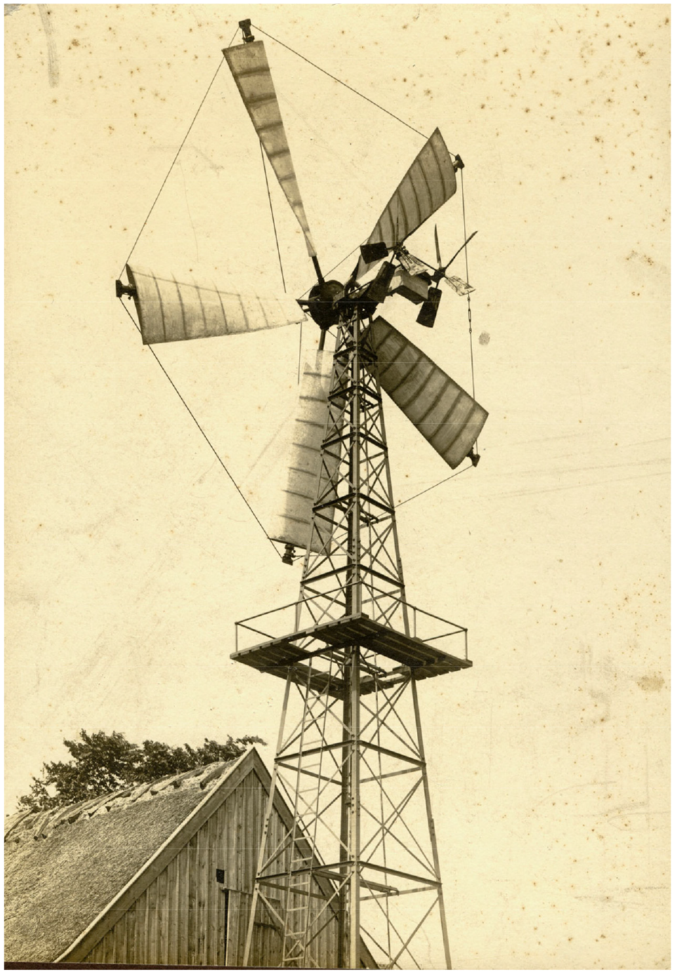
According to Hütter, Bilau installed a 9 m diameter prototype in 1924 that had tip-speed ratio of 3–4 (Hütter, 1973). In 1925–1926, Bilau installed a downwind turbine at a test field near Oxford, England that drove 9.6 kW DC generator (Heymann, 1995). To provide overspeed control, Bilau added air brakes on both the upper and lower surface of the blades toward the tip (See Figure 8).
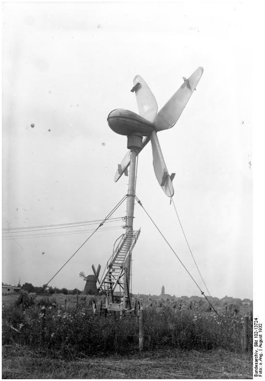
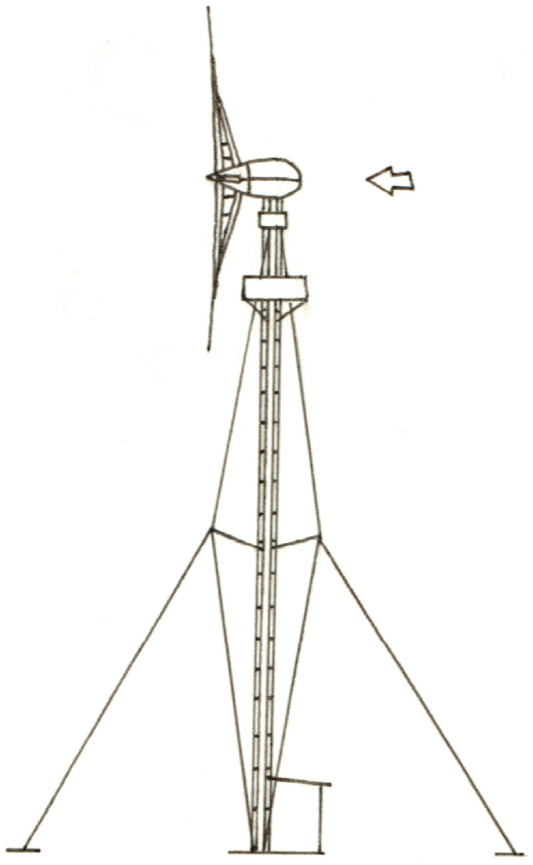
Bilau’s Ventimotor. Kurt Bilau’s Ventimotor probably at a test field near Berlin in the summer of 1932. The turbine was installed on both a wooden pole and on a steel tube, as shown here. Bilau’s turbine was also installed at test field near Oxford in 1925–1926. The rotor is downwind with air brakes and the dynamo was installed inside the stream-lined nacelle. (Bundesarchiv).
Flettner’s rotating rotor blades
Flettner and his rotors hark back to the early days in aviation and fluid dynamics. German aeronautical engineer Anton Flettner was also contemporary of German physicists Albert Betz and Ludwig Prandtl and French engineer Georges Darrieus. Flettner made important contributions to aviation, notably in helicopters, but it’s his experimentation with spinning cylinders using the Magnus effect that have come to bear his name.
Flettner is most well known for his rotor ships of the 1920s. However, in 1926, he built a horizontal-axis wind turbine 20 m in diameter in which he used four spinning cylinders as blades to drive a 30 kW generator (Putnam, 1974). Each blade incorporated a motor-driven cylinder 5 m long and 0.9 m in diameter. Despite Flettner’s grandiose projections for the design, the prototype was unsuccessful and Flettner’s backers lost interest (Heymann, 1995).
Flettner rotor technology languished until the oil crises of the late 1970s and early 1980s when interest was revived. In August 1983, a Flettner-driven wind turbine installed at a test site near Palm Springs, California made the cover of Popular Science magazine as the “next best thing” in wind energy. The device disappeared soon after and no more has been heard about it since. Despite its disadvantages, inventors periodically revisit the concept, most recently in Poland and Belorussia (Energetyka wiatrowa na Białorusi; Khammas; Wind turbine wiatrowa).
Russia
But it was the Russians who built the biggest experimental machine of the day, an achievement that is often overlooked. On a bluff overlooking the Black Sea outside Yalta, Moscow’s Central Institute for Wind Energy installed a 100-kW, three-blade wind turbine 30 m in diameter (Rapin and Noël, 2010). Commencing operation in 1931, the Balaklava turbine’s upwind rotor drove an induction generator that fed a 6300 V line to the 20 MW peat-burning plant at Sevastopol 20 mi from the site (Fleming and Probert, 1984; Putnam, 1974). 3 Though the turbine may appear crudely constructed, it remained in service until it was destroyed during the war in 1942, something that cannot be said for other wind turbines of the era.
The design presaged later experimentation, it used an induction generator and pitch weights on a variable pitch rotor. And it used ailerons as well. These would not be seen again for 50 years.
Unlike most wind turbines that yaw the turbine’s nacelle about the tower to face the wind, the Balaklava machine mechanically turned the entire tower on a circular track. This design feature wasn’t to be seen again until the mid-1970s with the Bendix-Schacle turbine in Moses Lake, Washington. And it hasn’t been seen since.
Windchargers
During the 1930s the Jacobs Wind Electric Company in Minneapolis, Minnesota was manufacturing thousands of small wind turbines for rural homesteads on North America’s Great Plains. Jacobs wasn’t the only manufacturer serving this market before rural electrification brought power to more and more rural areas, but it was one of the largest and one of the most well-known of the period. Paul Jacobs, a son of one of the firm’s founders, writes that the company sold 20,000 wind turbines before ceasing business in the mid-1950s (Jacobs Wind Electric) (See Figure 9).
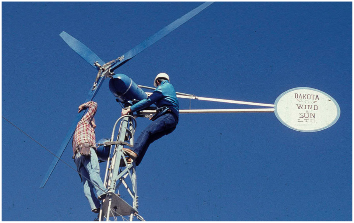
Jacobs Windcharger. The Jacobs design used three wooden airfoils upwind of the tower oriented by a tail vane. Production began in the 1930s and continued into the 1950s. With the revival of interest in wind energy during the 1970s, the rugged Jacobs windcharger was much sought after. Here two technicians replace the brushes on the DC dynamo at West Texas State University’s test field in 1979.
What is most striking about this era in North America was the size of the wind turbines being used. Americans were building very small machines. The largest Jacobs turbine of the era was only 4.3 m in diameter, powering a 3 kW direct-drive generator. The Danes, Germans, and French were experimenting with wind turbines 8–20 m in diameter for connection to the grid. Denmark’s Agricco was commercially installing wind turbines 13 m in diameter in the early 1920s, that is, a wind turbine nearly 10 times larger than the Jacobs turbine.
When American interest in wind energy was rekindled in the 1970s, it was these small turbines to which budding entrepreneurs first turned. Similarly, when Danes reintroduced wind turbines in the 1970s it was wind turbines similar in size to those of Agricco and Lykkegaard that they turned. This was to have a profound effect on the direction of the modern wind industry. The Danish wind turbines, while large for the day were of a size manageable by the small to medium size companies typical of Denmark then.
War years
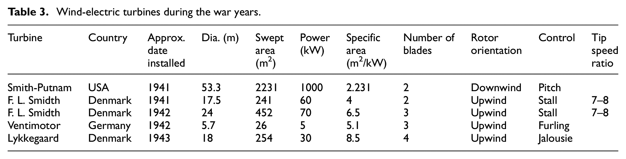
When war broke out in Europe development of wind energy effectively ceased in France and Russia. However, development continued in Denmark—of necessity once again. Surprisingly, work continued in Germany as part of the Nazi war machine. Meanwhile, work was continuing on the greatest North American experiment in wind energy until the great wind revival of the 1970s: the Smith-Putnam turbine (see Table 3).
Wind-electric turbines during the war years.
Smith-Putnam
In the fall of 1941 an ungainly wind turbine atop Vermont’s Grandpa’s Knob fed electricity into the lines of Central Vermont Public Service Company (Rapin and Noël, 2010). This was a first in North America. Until this time wind turbines had been used solely to charge batteries at remote homesteads in Canada and the United States.
The story of the turbine’s creation—and demise—is told in detail by one of the chief protagonists, Palmer Putnam, in his book Power from the Wind (see Figure 10) (Nielsen, 2010). The 53-m diameter, two-blade wind turbine drove a 1000 kW synchronous generator (Bruyerre, 2020). 4 To design, build, and operate the wind turbine from scratch—without any prior experience in wind energy—Putnam and the team organized by S. Morgan Smith company in York, Pennsylvania, had to overcome numerous technical and logistical problems. That they succeeded at all is a testament to their ingenuity and perseverance.
Smith-Putnam. The 1000 kW Smith-Putnam wind turbine used an unusual downwind, flapping two blade rotor 53.3 min diameter. Installed on Grandpa’s Knob in Vermont, it began delivering electricity to Central Vermont Public Service in October 1941. It operated intermittently until it threw a blade on 26 March 1945. It was the first megawatt-scale wind turbine. Machines of this size were not seen again for another three decades. Photo montage by Grant Voaden, Assistant Chief Engineer. (From the archives of Carl Wilcox).
The Smith-Putnam turbine remains unusual to this day for its choice of a downwind rotor with flapping hinges (Nissen et al., 2009). The hinges allowed the blades to cone downwind of the tower in gusts, allowing the wind turbine to dynamically balance gusts with the centrifugal forces of the spinning rotor. The large A-frame hinges also allowed the blades to change pitch. The combination of dampened flapping, and variable pitch enabled Putnam to control power to not exceed the maximum power of the synchronous generator.
Though it was downwind, Putnam wisely chose to actively yaw the huge machine rather than rely on passive yaw to orient the rotor downwind of the tower. However, Rapin and Noël note, the flapping rotor and its heavy, complex hinges were not well adapted to the rigors of commercial usage (Rapin and Noël, 2010).
In 1943 a blade bearing failed, causing the turbine to be shut down for 2 years because of war time shortage of materials. Upon inspection, the blade spars were found to be undersized for the loads, so doubling plates were welded in place. The rotor was then locked in place for the duration of the war.
During the hiatus loads on the blades were recalculated based on strain gauge measurements and found to be higher than first thought. Project consultants then advised that the turbine should be removed “as soon as it served its purpose” (Nielsen, 2010). The turbine was returned to service in 1945 and cracks were soon found in the blade root at the strengthening welds though operation continued in hopes of completing the test program.
The Smith-Putnam turbine then operated continuously for several weeks until late March 1945 when the repair weld failed and the turbine threw a blade, ending the program. It was three decades before anyone attempted a wind turbine of this size again.
Ventimotor and the Third Reich
After the Nazi’s seized power in 1933, they began a systematic program for assuring energy autarky or self-sufficiency. The development of wind turbines became a part—though never a big part—of this program. Some of the great names in automotive and wind turbine design were associated with the effort. None of the wind turbines themselves left much of a legacy, but the work on them did.
In 1940, the Porsche design bureau installed several small wind turbines at a test field outside Stuttgart. The smallest was a two-blade, 3.4 m diameter, 130 W machine, and the largest used a three-blade rotor 9.2 m in diameter powering a 10 kW generator. The sheet metal-covered blades operated at a relatively high tip-speed ratio of 7. The variable-pitch turbine sported an odd twin tail and the whole assembly resembled a race car of the period, probably influenced by Porsche’s wind tunnel experience with motor vehicles (Dörner, 1995).
Yet it was the work in the one-time capitol Weimar that left the biggest mark on wind energy. It was here that an ambitious Austrian sailplane designer taught engineering and in 1940 went to work for the Ventimotor Company while he worked on his doctorate. Ulrich Hütter’s subsequent thesis on wind turbine design principles was not unlike the task undertaken by Poul La Cour 40 years before, defining the “ideal” wind turbine.
Hütter’s biographer, Heiner Dörner, called Hütter the papst or pope of German wind energy. Whatever the sobriquet, Hütter left a lasting mark on wind turbine technology, but not as is often thought on the configuration of modern wind turbines (Dörner, 1995).
Heymann in his masterful history of German wind energy contains an extensive discourse on Nazi interest in wind turbines and the formation of the Ventimotor Company in late 1940 by rising stars in the Nazi party. Into this group stepped Ulrich Hütter, then a 30-year-old aeronautical engineer (Heymann, 1995). Hütter lived in Weimar from 1939 to 1943. In 1943 Ventimotor’s activities were sharply curtailed after the sixth Army’s defeat at Stalingrad and Hütter was called up for military service. One of Nazi Germany’s more notorious concentration camps, Buchenwald, was located about 5 mi northwest of Weimar.
Unlike many of those who followed in his footsteps, Hütter emphasized the importance that the esthetic design of wind turbines would have on subsequent decades. Hütter wrote in his thesis, says Heymann, “These [wind turbines] must … be of a timeless beauty, so that they do not in three or four decades hence burden a later generation with the heavy task of removing angular skeletons, by our indifference to the imponderable value of our environment.”
Reminiscent of Louis Constantine’s observation in the 1920s, Hütter also argued that a greater number of medium-sized turbines is superior to a small number of large turbines. This was a lesson that was lost on later German engineers who designed the ill-fated Growian wind turbine.
Hütter’s dissertation concluded that for tip-speed ratios between 4 and 7 three blades were the optimum number of blades in a rotor. This too was later ignored in the design of Growian and by Hütter himself in his later years as he devoted most of his research to two-blade turbines. Despite his dissertation, Hütter convinced himself that he could wring more economies from lightweight, two-blade turbines operating at high tip-speed ratios—those above seven—than he could from a three-blade turbine. In this he was proven wrong.
By the end of the war there were six turbines at Ventimotor’s test field. All were forgettable. Even Hütter’s 5.7-m diameter prototype was unremarkable, and a throwback to much earlier machines that used a pilot vane to furl the rotor in high winds.
In 1942, Ventimotor bought a F. L. Smidth 17.5-m diameter Aeromotor turbine from occupied Denmark for testing a directly connected 60 kW induction generator. It is interesting to speculate how the Aeromotor turbine could have influenced Hütter’s later work and led German engineers down a path far different—and more fruitful—than that taken by Hütter and the engineers who followed him.
The F. L. Smidth turbines of the war years did influence subsequent Danish designers of the post-war era, including one Johannes Juul.
Denmark and F. L. Smidth
During WWII, Denmark again turned to the wind as it had two decades before. By the time the war ended, Danes had installed nearly 90 wind-electric turbines, the most commercial-scale wind turbines of any one country until the great wind revival of the 1970s.
More than two-thirds of the turbines installed were the 30 kW Lykkegaard wind turbine patterned after La Cour’s klapsejlsmølle designed at the turn of the 20th century. However, there was a new entrant on the Danish scene—F. L. Smidth’s Aeromotors (Nielsen, 2010) (See Figure 11).
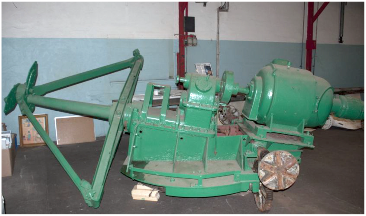
F. L. Smidth Aeromotor drive train. 1941 drive train for a two-blade stayed rotor installed by F. L. Smidth at Ullerslev on the island of Funen, Denmark. The original wooden blades were replaced with metal clad blades in 1954. According to Benny Christensen, board member of the Danish Wind Turbine Historical Collection (Danmarks Vindkrafthistoriske Samling) in Lem, Denmark, this turbine was the last F. L. Smidth in service and operated until 1960. Note the braced rotor, integrated drive train, and fantails (without the blades) for orienting the rotor into the wind.
F. L. Smidth became one of the world’s first firms to marry the field of aerodynamics to wind turbines. The diversified company designed machinery for working with concrete and used this technology to build concrete silos and chimneys. An affiliated company also built small airplanes. They combined these technologies and began manufacturing two-blade upwind turbines that unlike Lykkegaard used modern airfoils.
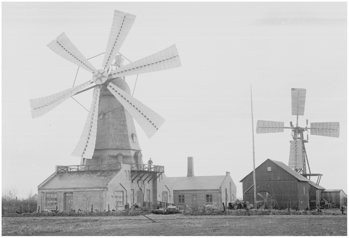
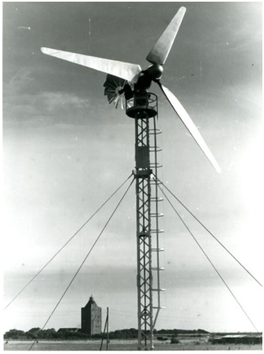
It was the second, much larger turbine that would prove most significant. This version used a three-blade, stayed rotor 24 m in diameter. Though it was rated at only 70 kW, the rotor was nearly twice the size of the two-blade version (see Figure 12). Like the Danish turbines that had come before, the rotor on both models were placed upwind of the tower and used fantails to mechanically point the rotor into the wind.
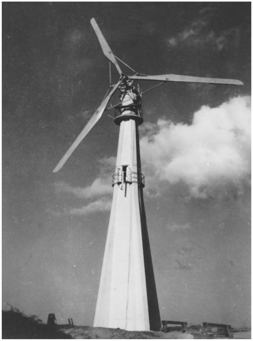
Three-blade F. L. Smidth Aeromotor. Later, larger version of F. L. Smidth Aeromotor installed at Skagen, the northernmost tip of the Jutland peninsula. The three-blade rotor was 24 m (79 feet) in diameter—nearly twice the size of the two-blade turbine—and was braced with struts and stays, a characteristic of later Danish wind turbines. This unit generated nearly 120,000 kWh in 1944, a remarkable performance for wind turbines of this period. (The FLS-files in Danmarks Vindkrafthistoriske Samling).
The F. L. Smidth turbines dwarfed the small machines Hütter had been experimenting with at Ventimotor. They were 10–20 times larger. These were not prototypes but commercial products that entered serial production. Altogether, there were some 19 F. L. Smidth Aeromotors operating by the end of the war. Not many by today’s standards, but enough to demonstrate their worth.
One striking feature of these early Danish machines was their longevity, a harbinger of the ruggedness that would make Danish wind turbines famous in the 1980s. F. L. Smidth’s two-blade version installed at Ullerslev in the early 1940s operated for 19 years. It was only taken out of service in 1960 when the power station was closed. Their three-blade model at Gedser on the island of Falster south of Copenhagen operated for 16 years (Nissen et al., 2009; Thorndahl, 2009). These were durable machines.
Altogether, Danish wind turbines generated 18 million kWh from 1940 to 1947 (Thorndahl, 2005). Though a small part of Danish electricity supply in percentage terms during the war, these machines were a welcome addition at Danish power stations short of fuel.
Again, wind delivered essential services when fossil-fuel was in short supply or simply unavailable—a lesson the world would have been wise to take to heart. Though a few turbines continued operating through the 1950s, the work of F. L. Smidth came to an end with the end of the war.
Post war years
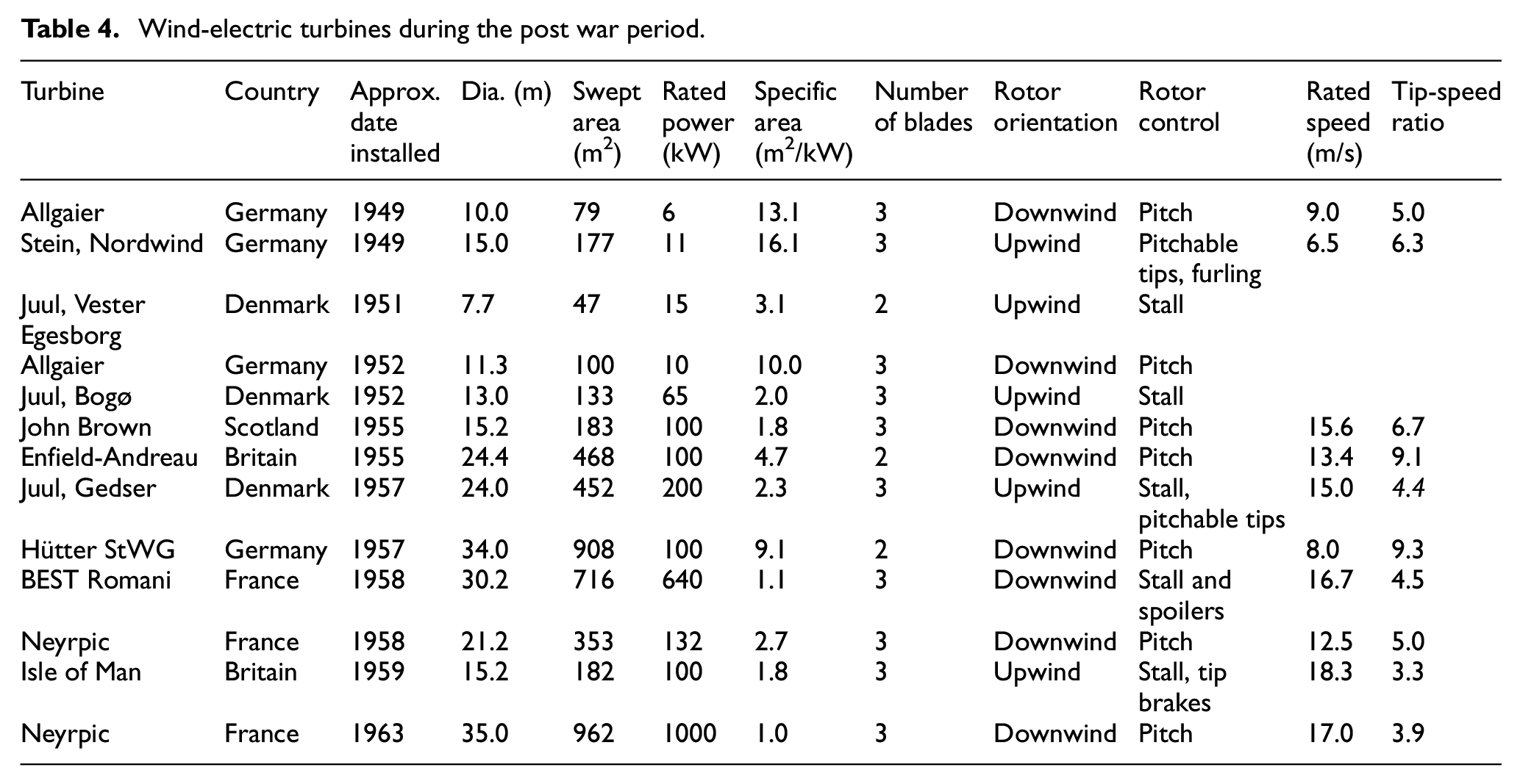
Remembering war time scarcity, several countries, and the recently created United Nations, launched programs looking at a role for wind energy. From the early 1950s to the late 1960s, programs in Germany, France, and Denmark dominated wind energy development (See Table 4).
Wind-electric turbines during the post war period.
Nordwind at Neuwerk
Dimitry Stein and his colleagues were among of the first in post-war Germany to design and build a wind turbine. Little known outside of German and French wind historians, Stein was working on his doctorate in engineering about the same time as Ulrich Hütter was completing his thesis on the ideal wind turbine. The path of the two couldn’t have been more different. Hütter worked for the Reich war effort. Stein was forced into hiding from the Gestapo.
In 1946, Stein and others founded the company Nordwind. They developed what they called a Universal Windmotor that could be used to pump water or generate electricity by delivering power to ground level via a vertical shaft.
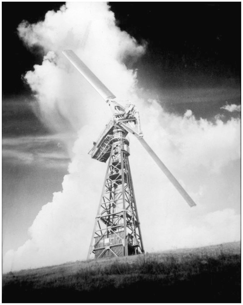
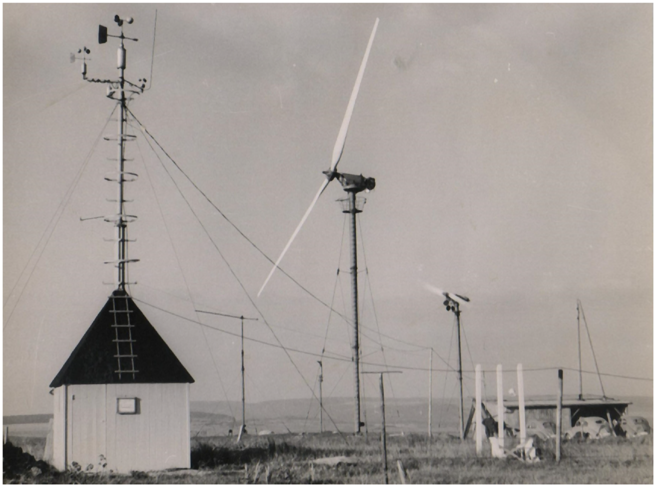
Nordwind won a contract in 1947 to install a wind turbine on the island of Neuwerk in the mouth of the Elbe River. In 1949, Nordwind installed its first Universal Windmotor to power the island’s lighthouse (see Figure 13) (Handschuh, 1991).
Nordwind 15 m diameter wind turbine on the island of Neuwerk in the Wattensee near the mouth of the Elbe. 1950 Photo by Alfred Ehrhardt. (Alfred Ehrhardt Stiftung).
At 15 m in diameter, Nordwind’s wind turbine was large for the day, sweeping as much area of the wind stream as the better-known product from the company Allgaier whose wind turbine was designed by Austrian aeronautical engineer Ulrich Hütter.
The Nordwind machine had several unique features by today’s standards. First, it drove a DC generator at ground level. Modern wind turbines generate electricity at the top of the tower in the nacelle. However, traditional European wind mills transmitted mechanical power through a vertical shaft for grinding grain. Similarly, early Danish wind turbines also used a vertical shaft to drive a dynamo at ground level. And we know that Stein had studied Danish design during the war (Stein, 1942).
Nordwind’s three-blade, upwind rotor also closely resembles the appearance of Danish wind turbines that became common in the 1970s and 1980s. The planform or shape of the blades look quite similar.
In another striking parallel between the Nordwind blades and those of the modern Danish wind revival were the overspeed control. The outer third of the Nordwind blades changed pitch to regulate power much like Danish wind turbines of the 1970s and 1980s used pitchable tips to limit rotor speed (I.N.R.A.A Adrar). The Nordwind turbine also used a large fantail to orient the rotor into the wind. The fantail could also be used to mechanically turn the rotor out of the wind during storms. Fantails were a common feature of both Danish and German wind turbines well into the 1980s.
While the historical record is sketchy, the turbine may have operated for a period of about 8 years. Stein emigrated to the United States in 1947 where he led a long career in business and academia. He never again worked in wind energy.
We can only imagine what Stein might have done if Germany had welcomed his contributions instead of persecuting him. Maybe he would have been able to continue working in his chosen field. He might have been a counterpoint to the more technocratic approach taken by Hütter and, thus, moving early German work closer to that of the Danes.
Though the Nordwind turbine has been long forgotten, it may have been the first modern wind turbine installed in Africa. Prior to its dissolution, Nordwind had won a contract with Algeria, subsequently shipping five to the country where two were installed to pump water. The other three turbines were still in their crates when Algeria’s war for independence from France broke out (Handschuh, 1991). One was installed in 1953 by le Service de la Colonisation et de l’Hydraulique in southern Algeria. The machine was used for a few months after independence in 1962 and stood idle until 2001 when a team began restoring it after 50 years (I.N.R.A.A Adrar).
Germany’s Allgaier
After the war, Ulrich Hütter began working for Allgaier, a German manufacturer in the automotive industry. His assignment, design a wind turbine that could be used in a number of different applications in both the developed and developing world.
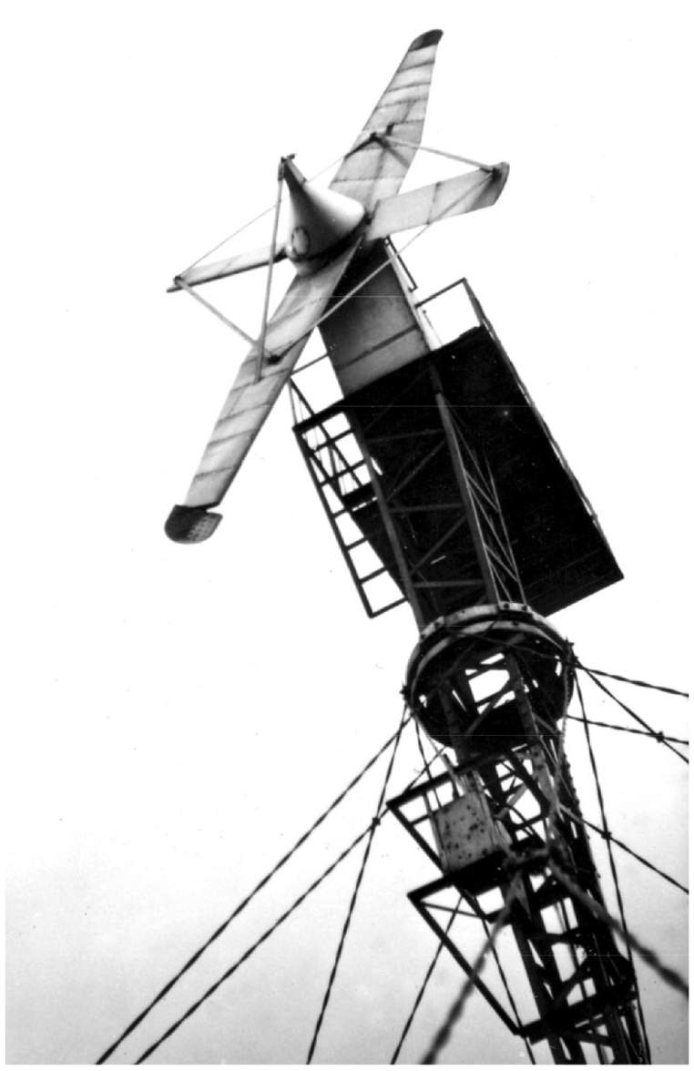
The turbine was a far cry from the clumsy turbine he built for Ventimotor (see Figure 14) in the early 1940s. In 1949 he erected his first Allgaier at a test field near Holzhausen in central Germany. Subsequently, Algaier began serial production in the early 1950s. The company built from 150 to 200 of the sleek three-blade, downwind design (Handschuh, 1991).
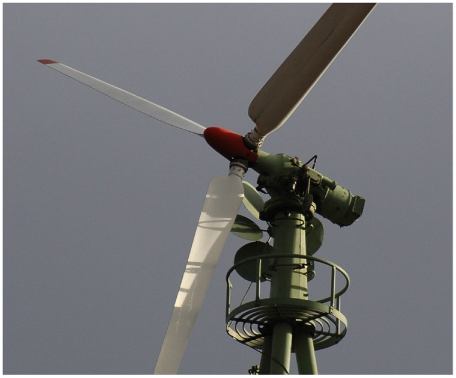
Allgaier. Three-blade downwind 11.3-m (37-foot) rotor with fantail developed by Urich Hütter in the early 1950s. Several museum pieces remain, including this one in Holzhausen, Germany. Note the work platform, integrated 10 kW drive train, blades with full-span pitch control, and characteristic Hütter flange at the blade root near the hub. Though it was a downwind turbine, it used a fan tail (the small rotor) to orient the rotor downwind, a feature overlooked by many later engineers. This unit is one of six that was installed by Klöckner-Moeller, a manufacturer of electrical components (2005).
The first batch of Hütter’s WE-10 were nominally 10 m in diameter and drove a 7.2 kW generator intended for off-grid applications. The turbines operated at a very high tip-speed ratio of eight, reportedly delivering a very high coefficient of performance of 0.47, both features that would come to characterize Hütter’s subsequent work (Heymann, 1995).
In contrast to some of the wind turbine designers before him and the many since, Hütter emphasized the rotor’s diameter in describing his designs, not the size of the generator that the rotor powered. For Hütter had early in his research concluded that it was the area swept by the wind turbine that would determine how much energy it could capture.
Thus, the rotor on the WE-10 was eventually enlarged to 11.27 m in diameter to sweep an even 100 m2. The larger rotor drove a 10 kW generator, giving the turbine a specific area of an even 10 m2/kW, nearly five times that of the Smith-Putnam turbine of the early 1940s. Large swept area, small generator size, and the resulting high specific area are another hallmark of Hütter’s design approach.
Though Nordwind’s turbine at Neuwerk was crude in comparison to Hütter’s sophisticated Allgaier design, Nordwind’s turbine also used a high specific area. This was unusual for the day and for many years to come.
Hütter would go on late in his career to design a wind turbine for Sweden that, although never realized, swept exactly 1 ha (10,000 m2), illustrating that he found beauty in round numbers and that, again, it was swept area that was important in design, not generator capacity.
Allgaier turbines were sold worldwide throughout the 1950s, making it one of the most widely distributed modern wind turbines before the great wind revival of the 1980s. One group of eight turbines was installed for polder drainage in the lowlands of northern Germany. This cluster of turbines was likely the world’s first modern wind farm. They operated in this capacity for the next decade (Oelker, 2005).
Hütter’s Allgaier turbine remains distinctive in the annals of wind energy. It used three slender airfoils that are bolted to the hub with a flange that would become Hütter’s most significant legacy. The rotor incorporated a sophisticated pitch mechanism for closely regulating rotor speed. The integrated drive train creates a compact pleasing nacelle. And unlike many later downwind designs that tried to emulate Hütter, the rotor was mechanically oriented downwind rather than rely on passive yaw. And the whole assembly typically rested atop a tower of three tubular legs with a work platform. Until the rise of the Danish wind industry, this was the world’s most successful commercial-scale wind turbine.
However, Hütter began a commissioned project to design a wind turbine nearly 10 times larger. In doing so, he greatly advanced the fledgling field of composite materials, and carried his quest for high tip speeds to the extreme. The result was the StGW-34, a 34-m diameter wind turbine with a two-blade, teetering rotor. As previously, the 100 kW turbine was specifically designed to have a very high specific area of nearly 10 m2/kW (See Figure 15).
StWG-34 at a test field in the Schwabian Alps. The of climax of Ulrich Hütter’s wind turbine development, the StWG-34 was a two-blade downwind experimental wind turbine sweeping nearly 1000 m2, and driving a 100 kW induction generator. With a tip-speed ratio of 9.3 it was one of the fastest running of the “fast runners.” However, Hütter’s ultimate achievement was the development of the attachment of the fiberglass or composite blades to their root flange. Danes would later make the Hütter flange famous. (From the archives of Etienne Rogier).
The StGW-34 was connected to the grid at a test field in the Swabian Alps in December 1957, and subsequently began testing in 1958. It operated intermittently as a test vehicle until it was scrapped a decade later. As an experimental turbine it suffered extensive outages, eventually throwing a blade in 1961.
It was the design—and the redesign—of these blades in fiberglass that pushed the boundaries of this new technology. The blades were extremely long for the period. This size wouldn’t be seen commercially until three decades later. More importantly to the development of wind energy was how Hütter attached the fiberglass filaments around the bolts—or bolt holes—in a wide diameter flange. This became known as the Hütter flange.
Hütter’s legacy is not high tip-speed ratios, or light-weight downwind, teetered rotors. From his dissertation to the StGW-34, Hütter had proposed a series of high-performance downwind rotors, including a brief foray to a one-blade prototype with an extremely high tip-speed ratio of 12. These design characteristics have all proven commercially unsuccessful.
Instead, Hütter’s legacy is his esthetic sense that wind turbines must be pleasing to the eye. It is also his insistence on wind turbines designed for high specific area that can be used in areas of low to moderate winds—where most of the world’s people live. It is also his contribution to making blades from composite materials and for a practical and durable method of attaching them to the rotor hub: the Hütter flange.
Hütter gave us the modern wind turbine blade. It was not Hütter that gave us modern wind turbines. That honor goes to a Dane.
Denmark’s Johannes Juul
Johannes Juul was at the opposite end of the academic and institutional spectrum from Hütter. Juul had little formal education and trained in the Danish craft tradition, graduating from the Askov folkehøjskole in la Cour’s first class for windmill technicians. But like la Cour before him, and his contemporary Hütter, Juul was inventive and resourceful. Forty years after completing his wind technician classes, Juul reexamined wind and for the next 10 years his work led the world in the development of practical wind energy.
The impetus for Juul’s work was continuing shortages of fuel in Denmark and its high cost in the immediate post-war period. In the spring of 1947, Juul began research and development on a new wind turbine for his employer, SEAS, 5 the utility serving the region surrounding Copenhagen.
By 1948, Juul was testing blade designs in a wind tunnel that—like la Cour before him—he built of necessity. In 1950, Juul began testing a prototype 8 m in diameter.
The turbine at Vester Egesborg was a far cry from the turbines that would follow, but it shows that Juul was willing to experiment and not simply take the three-blade F. L. Smidth design and proceed from there (see Figure 16). His prototype used two cantilevered blades downwind of the tower. Unlike the F.S. Smidth turbines, there were no struts and stays. Juul, like so many wind engineers since, was not immune to the lure of promised simplicity and low cost offered by a two-blade rotor downwind of the tower.
The Mill at Vester Egesborg. Johannes Juul’s first attempt at building a wind turbine. The 7.7 m diameter, 15 kW, wind turbine used two fixed-pitch blades upwind of the tower braced with stub blades, struts, and stays, a characteristic seen on later Juul designs. Note the pitchable blade tips. (The Danish Museum of Energy).
Unlike F. L. Smidth’s turbines, which had predominantly driven DC dynamos, Juul went back to Agricco’s use of asynchronous (induction) generators for direct connection to the then rapidly expanding AC network. And instead of pitch control requiring a sophisticated hub as on Hütter’s Allgaier turbine, Juul used a stall regulated rotor. According to Danish energy historian Jutte Thorndahl, it was the skilled combination of the asynchronous generator and stall regulation that was Juul’s technological breakthrough (Thorndahl, 2005).
Stall “regulation” is simple, but it has limitations. It only works if the rotor operates at a constant speed and if the generator is large enough to keep the rotor fully loaded in strong, gusty winds. If the generator fails, rotor speed quickly increases, stall is no longer effective, and the rotor can speed up to destruction. It’s no surprise then that Juul soon replaced the Vester Egesborg turbine’s 10-kW generator with a 15-kW induction generator.
Juul also learned that the slim blades were not strong enough on their own and added struts and stays, a characteristic of Danish wind turbines of the day. Importantly, he turned the nacelle to face the wind, abandoning the downwind design.
The Vester Egesborg turbine also demonstrated probably one of the most significant developments in wind energy: pitchable blade tips. Despite Juul’s belief in stall regulation, he provided a mechanism for protecting the rotor from overspeed in case the generator failed in high winds. This mechanism was simple, yet profound. The outboard section of the blades toward the tip were movable and could change pitch if the rotor went into overspeed, protecting the wind turbine from self-destruction. This was the same strategy employed by Stein in the Nordwind turbine at Neuwerk, and the in the Russian D-12 and D-18 designs being built in 1956 (Elistratov, 2013; Windmotor D-12 Image).
While not foolproof, this one technology was the principle reason that Danish wind turbines became so successful during the California wind rush of the early 1980s. Relative to their competitors, Danish turbines survived storms in California’s windy passes in far greater numbers, thus making them more reliable than technically more complex wind turbines.
The mill at Bogø
In 1952, SEAS replaced an F. L. Smidth Aeromotor at Bogø with a 13-m diameter turbine of Juul’s design. The rotor used three blades upwind of the tower with Juul’s pitchable blade tips. Juul used a prominent bowsprit with struts and stays to brace the thin aerodynamic blades. This was the distinctive configuration that Juul would make famous a few years later at Gedser on the island of Falster.
The Bogø prototype performed surprisingly well for such an early machine. In one 9-month period the turbine ran unattended (see Figure 17). Then the turbine was stopped for inspection and returned to service, said Juul in a report to the UN in 1961 (Juul, 2018). Even by the standards of modern wind turbines during the 1980s wind revival, the Bogø turbine was highly productive, delivering an average specific yield—one of the wind industry’s measures of performance—of 600 kWh/m2/year during an 8-year period (Thorndahl, 2005). This was double the performance of the F. L. Smidth turbines of the previous decade.
The Mill at Bogø. The forerunner of Juul’s Gedser turbine. The Mill at Bogø was 13 m in diameter and drove a 65 kW induction generator. Like his later Gedser design, Juul’s Bogø mill used three fixed-pitch blades upwind of the tower with a prominent bowsprit, struts, and stays. (The Danish Museum of Energy).
With the experience gained from these two machines, Juul began work on his crowning achievement, the mill at Gedser, the forerunner of later Danish wind turbines.
The mill at Gedser
Gedser, a small ferry terminal on the island of Falster 150 km (90 mi) south of Copenhagen, is iconic in the field of wind energy. It’s at Gedser where the modern wind industry began (Karnøe and Garud, 2012; Meyer, 1995; Nielsen, 2010).
There had been a wind turbine at Gedser before Juul. In 1944, F. L. Smidth had installed one of its Aeromotors on the well-exposed peninsula. Juul designed a scaled up version of his Bogø prototype to match the 24-m diameter of the F. L. Smidth turbine. This was a big leap for Juul. His Gedser design swept three times the area of his earlier machine.
SEAS installed Juul’s turbine in 1956 and put the machine into service in 1957. The Gedser mill remained in regular operation from 1959 through 1967 when the turbine was taken out of service after a failure in the chain drive system.
Like the Bogø turbine before it, Juul’s Gedser mill performed well, particularly in the early years, delivering yields of up to 800 kWh/m2/year. During its lifetime, the turbine generated 2.2 million kWh, producing nearly 370,000 kWh during its best year. In a 6 years period, the Gedser turbine generated an average of 275,000 kWh/year (Thorndahl, 2005).
The turbine used an upwind, three-blade rotor braced with struts and stays from a prominent bow-sprit (see Figure 18). It used slim, fixed-pitch airfoils and drove a 200 kW induction (asynchronous) generator at relatively constant speed. The rotor’s power was limited by stall of the fixed-pitch blades. For overspeed protection, the rotor used automatically deployed pitchable blade tips. Unlike the designs of F. L. Smidth and Hütter, the rotor was oriented mechanically with an electric yaw motor rather than a fantail.
Gedser mill. The grandfather of the Danish design concept. Designed by Johannes Juul, a former student of Poul la Cour, the ungainly but durable machine used struts and stays to brace the rotor as in the F. L. Smidth turbines that preceded it. The turbine is now on display at the Danish Museum of Energy. Note the pitchable blade tips. These were one of Juul’s most significant technical innovations and led directly to the success of Danish wind turbines in the 1980s. (The Danish Museum of Energy).
Juul, who died in 1967, left a lasting legacy to not just Danish wind engineers, but to the world. It was his design of the Bogø and Gedser mills that eventually became known as the Danish concept: three blades upwind of the tower, and a stall regulated rotor with pitchable blade tips for overspeed control. It was Juul’s clever combination of stall regulation and pitchable blade tips that were fundamental to subsequent wind turbine design. Other hallmarks were the simple rugged construction that together led to the durability necessary for commercial operation for years on end.
Both the F. L. Smidth turbine and Juul’s turbine were still standing at Gedser in 1974 when researchers from NASA and what was to become the US Department of Energy (DOE) visited the site following the first oil crisis. The Danes warned NASA that placing the rotor downwind of the tower as NASA intended for its 100 kW experimental model would create problems—and that it did.
Juul’s Gedser turbine was so robust that despite being idle for a decade it was returned to service in 1978 for tests paid for by the United States. When Denmark looked again to wind energy for help in meeting one more energy crisis, the country had a working model still standing.
Juul and Hütter were not alone in developing wind turbines in Europe at the time. There was a small program in Britain and a much larger effort in France as well.
France
While the allies were preparing to land on the beaches of Normandy, a French engineer in occupied France was giving a presentation on the role of wind energy after the liberation. Pierre Ailleret soon became a central figure in the newly created Electricité de France (EDF) when post-war France nationalized its electricity system in 1946. He quickly set about putting his vision into action when he became EDF’s director of research by creating a division for wind energy. Ailleret would lead this work for the next two decades—the most extensive national undertaking of its kind at the time, presaging the large—and expensive—national programs in the United States and Germany in the 1970s (Rogier, 1944).
Like Constantin, Ailleret envisioned batteries of wind turbines supplying the grid. More importantly, he realized that wind energy could play a much greater role in electricity supply if it could be integrated with France’s existing hydro system (Rogier, 1944). This was not unlike Juul’s unrealized vision for Denmark with its use of Sweden’s hydro power (Nielsen, 2010).
Ailleret’s research found a remarkable match between France’s hydro and wind resources. Hydro peaks in the spring and summer. Wind peaks in the fall and winter. What Ailleret needed were wind turbines and he set out to find companies capable of building them.
Ailleret and EDF settled on two simultaneous programs: one by BEST-Romani, the other by Neyrpic. The experimental French turbines were comparable in size to Hütter’s StGW-34 prototype. Thus, they were large turbines for their day and much larger than Juul’s Gedser turbine. Unlike Hütter’s design, both turbines had very high power ratings, giving them very low specific areas. Yet both French programs continued the engineering elite’s fascination with downwind, passive yaw turbines.
BEST-Romani
Lucien Romani, a self-taught engineer, was familiar with the role of the wind in aviation, automobiles, and dune formation. In 1946, he co-founded BEST (Bureau d’Etudes Scientifiques et Techniques) what we would call today a scientific think tank. Working closely with EDF for several years, BEST sought to develop a wind turbine at Nogent-le-Roi, a low-wind site north of Chartres in 1956 almost a decade after it was first conceived.
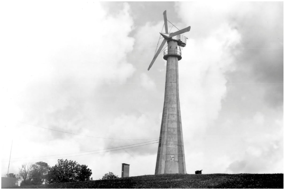
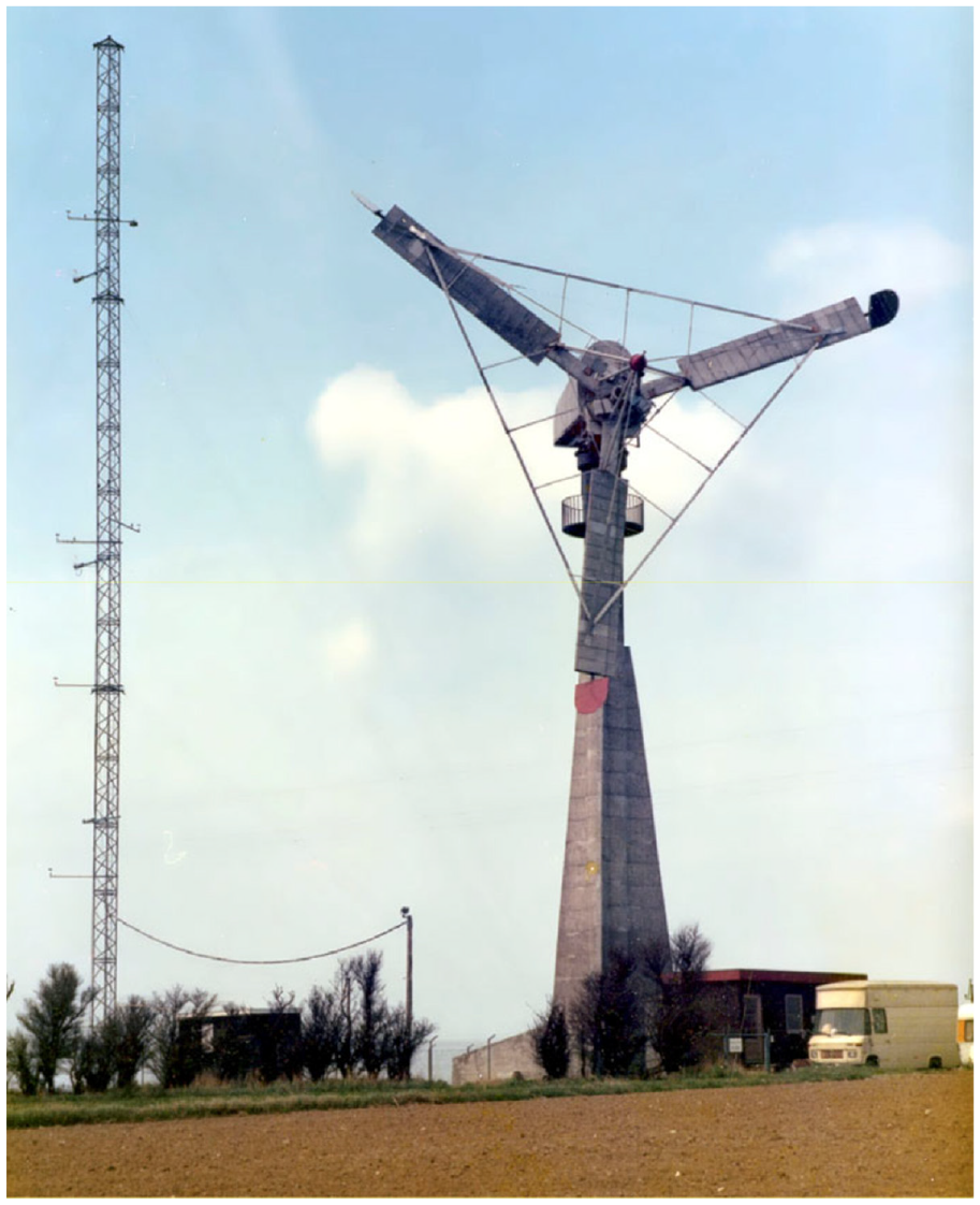
The BEST-Romani turbine was unusual in several aspects. The 30-m diameter wind turbine was erected on a combination tubular tower atop a tripod truss. The tubular tower section included a fairing to minimize turbulence striking the three-blade downwind rotor. The faring yawed with the wind turbine in response to changes in wind direction (See Figure 19).
BEST-Romani. The 800 kW BEST wind turbine designed by Lucien Romani. The 30.2 m diameter, fixed-pitch rotor was oriented downwind of the aerodynamically fared, tilt-up tower. The turbine had one of the lowest specific areas (less than unity) of any wind turbine ever built. (From the archives of Jean-Luc Cavey, www.eolienne.cavey.org. All rights reserved.).
Surprisingly, the whole of the massive machine—including the truss tower—was hinged and could be tipped to the ground for service and repair. Unlike Juul and Hütter, the BEST-Romani turbine didn’t use an induction generator, opting instead for a synchronous alternator, like that in the Smith-Putnam machine 15 years before.
Testing began in 1957 and the turbine operated from spring 1958 to spring 1962. EDF conducted numerous studies on vibration, pitch regulation, excitation, connection to the grid, yaw, as well as noise. Oddly, they found that the turbine performed better in free yaw than it had in wind tunnel experiments.
Like other stall regulated turbines to come, the turbine’s peak power exceeded its rated power—substantially. During a storm in the fall of 1959 the turbine reached 1025 kW, or 1.6 times the turbine’s rated power of 640 kW. 6
All in all, EDF was satisfied with the results, but they and BEST-Romani then took a step to far. In the spring of 1962, they installed a new higher-speed rotor to reduce a stage in the gearbox despite tests showing a risk of an aeroelastic vibration. The redesigned rotor operated for only 300 hours before losing a blade in the fall of 1963, bringing a sudden end to the program (Rapin and Noël, 2010).
Vadot and Neyrpic
The other effort was led by consulting engineer Louis Vadot in conjunction with Neyrpic (Ateliers Neyret-Beylier and Picard-Pictet), a manufacturer—like F. Morgan Smith Co. in the Smith-Putnam project—of hydro-electric turbines. Neyrpic was a major industrial company and the EDF contract was part of an ambitious program by the company to develop wind energy in France. They would later become famous for the bulb turbines they developed for EDF’s 1966 La Rance tidal barrage—until recently the world’s largest. The company had also been active in wind energy due to the work of consulting engineer Louis Vadot (Bruyerre, 2020).
Neyrpic eventually installed a series of two experimental turbines at Saint-Rémy des Landes, a windy site on Normandy’s Cotentin peninsula. In contrast to BEST-Romani, Vadot chose an asynchronous generator because induction generators were simpler to control and connect to the network than synchronous generators. They were also inexpensive and could become an integral part of industrially-produced wind turbines.
In the late 1950s, Vadot had realized that wind energy would more likely become cost-effective when it achieved series production than it would by the development of some unforeseen technology. Series production would cut the cost per installed turbine, much like it had for automobiles (Rogier, 1999).
Vadot’s began testing his first turbine in 1958. Testing continued for the next 4 years on the turbine with a three-blade rotor 21.2 m in diameter (See Figure 20). The downwind rotor used variable pitch blades for overspeed control, but operated at a constant speed. The blades were unusual, assembled from aluminum and with the chord or width in two steps. After losing the a blade in 1959, Vadot installed a more advanced design using composite materials and tested it from 1962 to 1964. Though originally configured with fantails to mechanically orient the rotor downwind, the machine was operated in passive yaw after replacement of the original rotor.
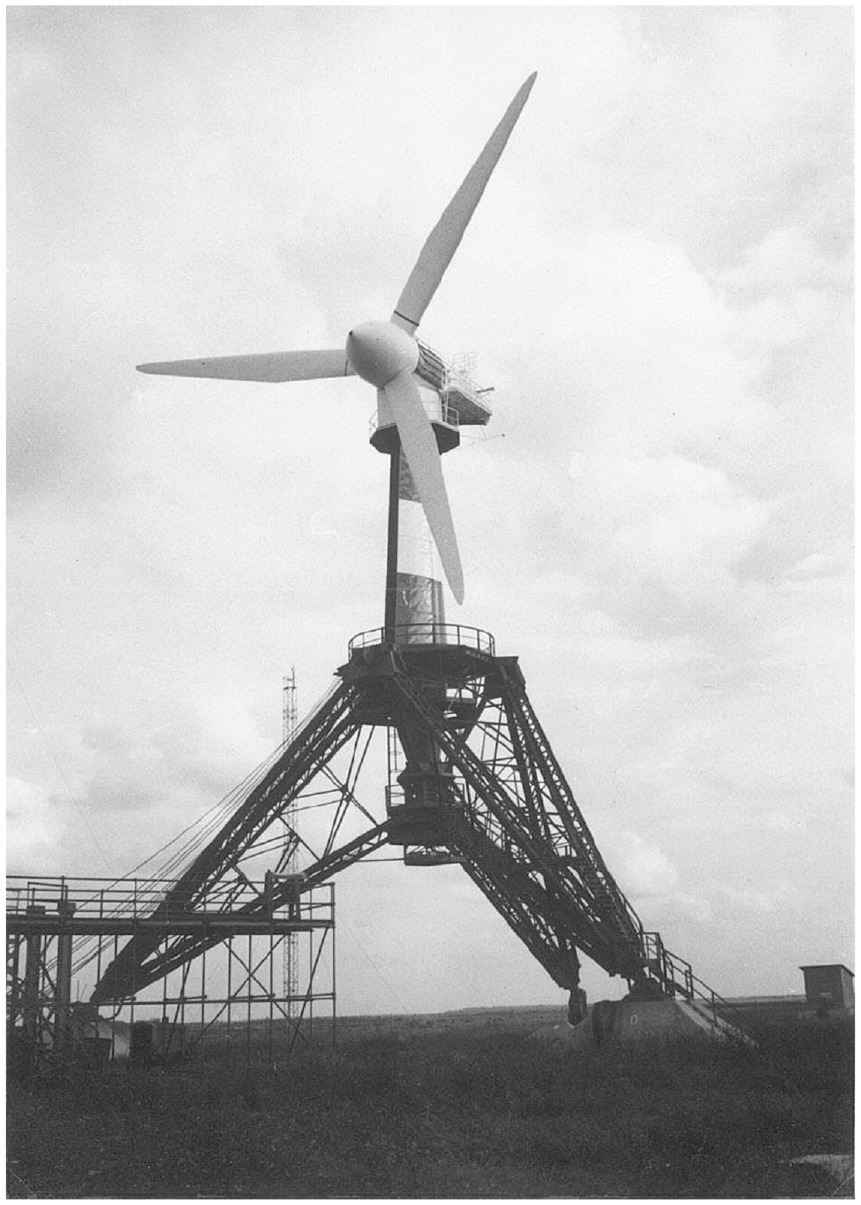
132 kW Neyrpic. The second iteration of the first prototype in EDF’s wind program of the 1960s used composite blades in a rotor 21.2 m in diameter. Of the three turbines in the EDF program, this version was the most successful, generating 700,000 kWh from 1962 to 1966 at a windy site on the Cotentin peninsula. (From the archives of Etienne Rogier).
The 21.2 m was surprisingly successful for the day. Importantly, it showed to EDF’s satisfaction that the design could regulate the operation of an induction wind turbine both mechanically and electrically. From 1962 to 1966 the turbine generated 700,000 kWh, less than projected for the site, but it turned in a “honorable performance,” according to R. Bonnefille in a retrospective on the program (Bonnefille, 1975). Unfortunately, that couldn’t be said for the second Neyrpic prototype.
EDF commissioned a larger version, and Vadot developed the 35-m model. The second turbine was nearly three times larger than his first turbine and comparable in size to Hütter’s StGW-34. Yet Vadot rated his second unit at an incredible 1000 kW—10 times that of Hütter’s prototype—giving the turbine a specific area of 1 m2/kW! Installed in mid-1963, the turbine operated until the summer of 1964 when it destroyed the thrust bearings.
As with the BEST-Romani failure, the failure of Neyrpic machine allowed EDF to abandon the development program and close their wind division in 1966. At the time, the cost of electricity from burning oil was cheaper than that from the experimental wind turbines and EDF was already moving toward a national commitment to nuclear. France had developed a nuclear bomb, and, like the United States at the time, was trying to find a civilian use for its weapons program.
As seen a decade later in similar national programs, the participants claimed success, but walked away without any lasting technology or products. The centrally-directed research by EDF and its contractors’ focus on downwind, passive yaw design foreshadowed the failure of top-down technology development seen in the 1970s and 1980s.
Great Britain
Post war Britain, like countries on the Continent, were also experiencing fuel shortages, price increases, and fears that demand for coal and oil would soon outstrip the resources available. Economic hardships for both the victors and vanquished suggested that each nation would better off if they used more of their own indigenous resources instead of paying to import fuel. Their electricity networks would also be more resilient using a variety of generating sources rather than becoming more dependent on fossil fuels (Golding, 1976). Consequently, the Electrical Research Association (ERA) formed the wind power committee to study the role of wind energy in Britain.
Like EDF in France, the British Electrical Authority was created after the war to nationalize the country’s electrical generation and distribution system, eventually evolving into the Central Electricity Generating Board in 1958. Edward Golding, considered the father of wind energy in Britain and the author of one of the seminal books on wind energy, became the wind power committee’s technical secretary.
With funding from the British Electrical Authority, ERA began a program to develop three 100 kW wind turbines: one in the Orkney Islands, one in Wales, and another on the Isle of Man. These were windy sites that had been identified by Golding in an extensive wind resource assessment of the British Isles.
John Brown, Orkney
Scottish fabricator John Brown Engineering installed an experimental three-blade downwind turbine using a complex variable pitch rotor in the Orkney Islands in 1955 7 (see Figure 21).
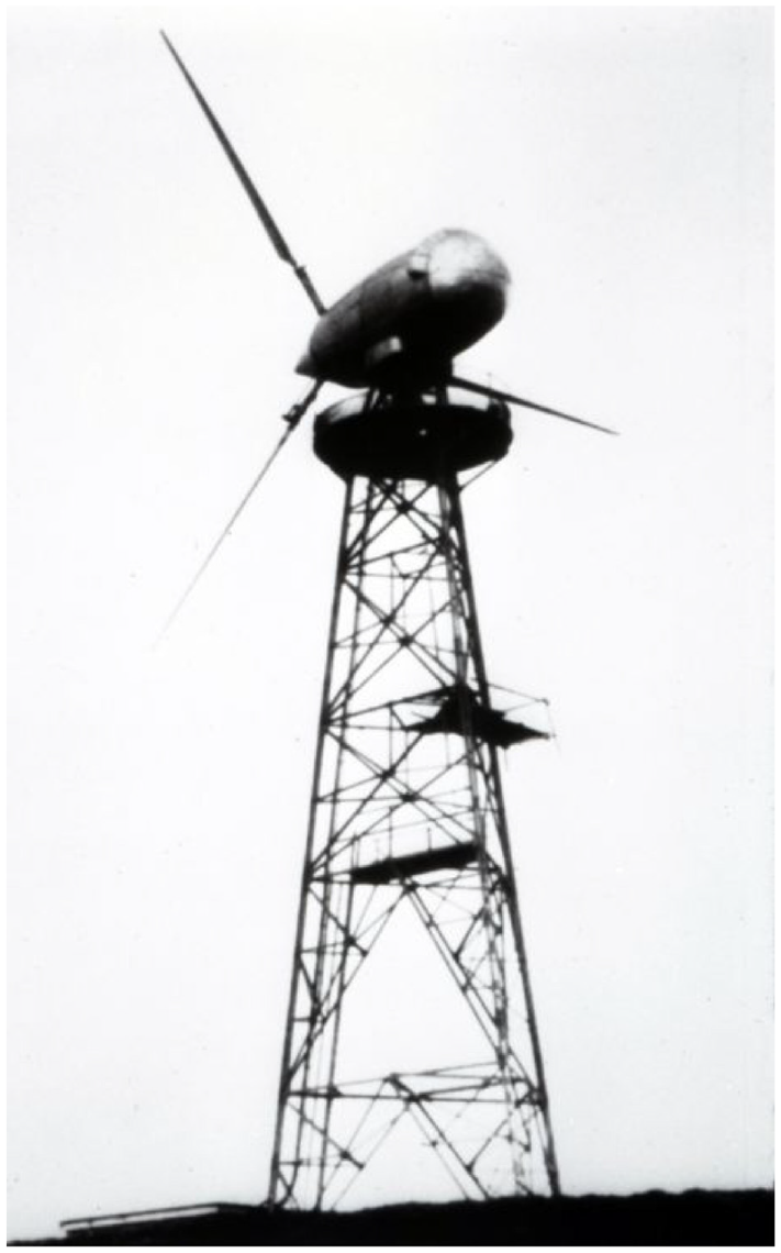
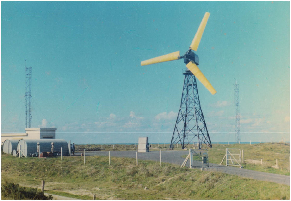
John Brown 100 kW. John Brown Engineering 50-foot (15.24 m) diameter 100 kW downwind experimental turbine at Costa Head, Orkney, Great Britain in 1955. Operated only intermittently connected to the island’s diesel network before being removed. (From the archives of Vaughan Nelson via NASA).
The original design used an 18.3 m diameter rotor rated at 13.4 m/s but was reduced to 15.2 m in diameter with a higher rated wind speed of 15.6 m/s as work proceeded. The turbine featured a complex hub that allowed each blade to cone downwind independently against a hydraulic damper in a manner similar to that previously used on the Smith-Putnam turbine. The blades used a laminated wood spar, wood ribs, and a plywood skin covered in plastic (Costa Head Experimental Turbine).
The Costa Hill site was one of the windiest in Great Britain with an average annual wind speed of 11.2 m/s (Golding, 1976). The high winds and turbulence coupled with the site’s remoteness resulted in intermittent operation connected with the diesel system on the main island of Orkney before it failed (Nelson, 2014; Owens, 2019). There wouldn’t be another wind turbine installed in the Orkneys for three decades (Costa Head Wind Turbine Video).
Andreau pneumatic wind turbine
One of the more novel wind turbines of the post war period was that developed by Jean-Edouard Andreau using suction as he termed it in French “dépression.” The sleek, gearless wind turbines Andreau developed reflected his background as an industrial designer known primarily for his auto car bodies. The principle was simple in theory. As the rotor spun, the hollow blades would draw air into the tubular tower through a turbine-generator by holes in the end of the blades. The practicality and efficiency of this approach was another matter.
Though French, and though EDF, the state-owned utility, considered his concept, it was the British that adopted the concept as its own. In 1947 Andreau installed a three-blade upwind turbine 6.5 m in diameter near Orleans, France in cooperation with EDF. He built a second prototype, a three-blade 8.5 m diameter downwind machine rated at 8 kW that was self-orienting. Neither machine was commercialized. Meanwhile he proposed a monstrous 55 m diameter 4.5 MW to EDF and a 21 m diameter, 150 kW, three-blade version to De Havilland. EDF didn’t accept Andreau’s proposal, but De Havilland did. After 2 years of testing the two prototypes, Andreau sold the design to the British firm De Havilland Propellers in early 1950 (Réalisations éoliennes).
With De Havilland producing the rotor, Enfield Cables installed a 24.4 m downwind prototype of what’s been dubbed the Enfield-Andreau turbine in 1951 for Britain’s Electricity Research Association. The De Havilland turbine used only two blades, varying significantly from Andreau’s prototypes.
The site chosen in Wales was rejected because of local opposition and the alternative site near St-Albans in Hertfordshire, England was unsatisfactory in retrospect. Turbulence from nearby trees caused serious vibrations in the rotor.
The project was soon abandoned after inconclusive tests (Bonnefille, 1975; Fleming and Probert, 1984; Rapin and Noël, 2010).
Subsequently, Électricité et Gaz d’Algérie bought the turbine and installed it on a windy hill at Grand Vent near Algiers, Algeria in 1957 8 (Erection d’une éolienne génératrice électrique; Rapin and Noël, 2010).
Driving a synchronous alternator, the turbine was designed to generate 100 kW at wind speeds of 13.5 m/s and continue to produce up to wind speeds of 29 m/s when the variable pitch blades would feather. Testing began in November 1957 (Delafond, 1961). Problems with orienting the rotor, and air leaks in the rotating joints were redesigned (Bonnefille, 1975). Tests resumed in the fall of 1959 when the project was abandoned because it was too difficult to protect the site as Algeria’s war for independence loomed (Bonnefille, 1975; Delafond, 1961).
The turbine operated for only 180 hours, producing from 80 to 130 kW, rivaling the poor performance seen in General Electric’s Mod-1 and MAN’s Growian 20 years later (Bonnefille, 1975).
Regardless of the tests on the smaller versions, the Andreau turbine was found to be only 20% efficient due to losses mounting as the air moved through the multiple stages of the tower, turbine, rotor, and blades (Bonnefille, 1975). Novelty alone wasn’t sufficient for success.
Though the great grandson of Andreau tried to reintroduce the concept in 2018, no further development has been made (Réalisations éoliennes).
Isle of man wind turbine
The most successful of the British wind turbines of the period is also the least well known. Why that is so, remains a mystery. The wind turbine was operated for The Isle of Man Electricity Authority and remained on site for at least 5 years, far longer than either the Enfield-Andreau or John Brown turbines.
Installed in 1959 west of South Barrule, the 15.2 m diameter wind turbine used three fixed-pitch blades upwind of the tower to drive the wind turbine at 100 kW at a wind speed of 18.3 m/s with a rotor speed of 75 rpm (Golding, 1976; Windmills of The Isle of Man). (The turbine in seen in Figure 22.)
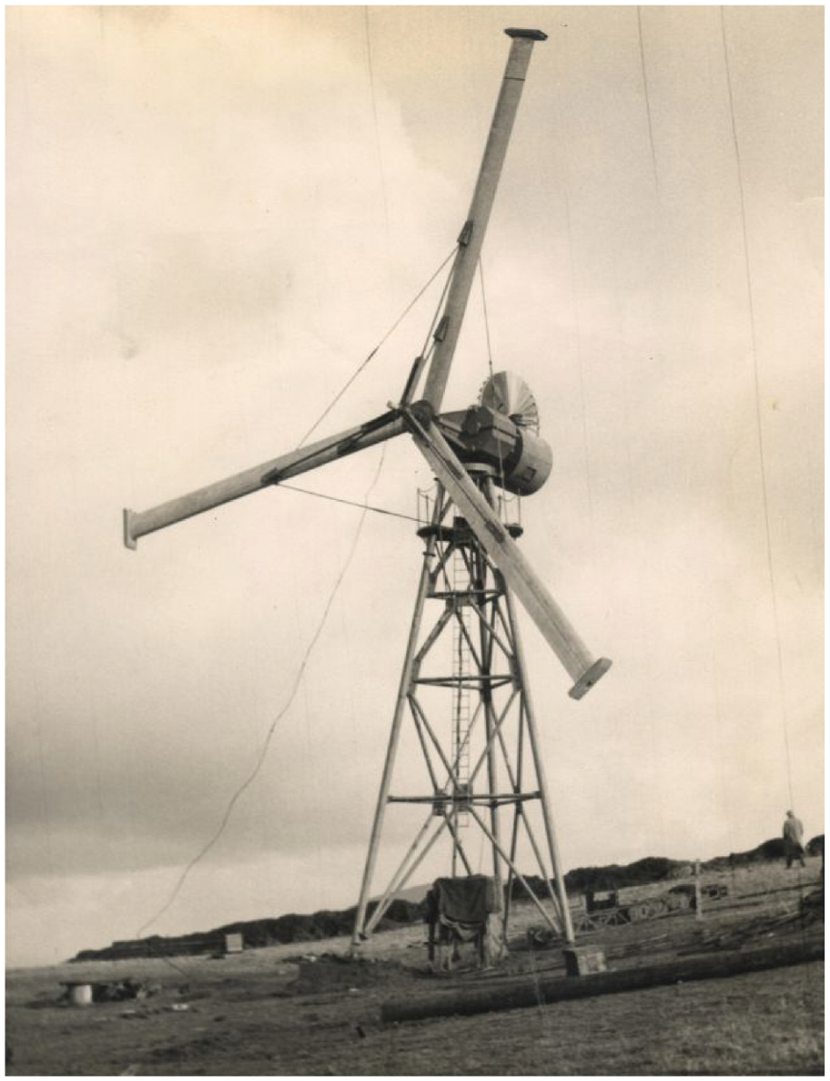
Isle of man prototype. The most successful of the British experiments with wind turbines during the post war period. The 15.2 m wind turbine used a three-blade rotor upwind of the tower, defying a growing convention toward downwind designs. The turbine also controlled overspeed conditions with tip brakes, a feature that wouldn’t bee seen again for another two decades. (From the archives of Etienne Rogier. All rights reserved.).
The site at South Barrule had been identified by ERA’s wind studies as a good location with an annual average wind speed of 10.1 m/s (Golding, 1976). Where the turbine was actually installed is unclear, Elliott simply says the site had a “moderate” wind regime, suggesting it was not located on the summit of the hill. Nevertheless, the turbine produced some 230,000–240,000 kWh/year when it was in full operation (Elliott, 1975). If true, such performance was exceptional for the day (1250 kWh/m2/year) and wouldn’t be seen again until the Danish wind revival of the 1980s was in full swing.
In comparison to the other two turbines, the Isle of Man machine was crude. It used a fantail to orient the rotor upwind of the tower rather than a mechanical yaw system as in the John Brown turbine. It was ungainly. The rotor was mounted directly on an integrated gearbox, possibly a forerunner of American and some Danish designs 20 years later. There was no nacelle at all, unlike the streamlined nacelle, blades, and tower faring on the Andreau turbine. The blades were not cantilevered like that on the Andreau turbine or John Brown design. The Isle of Man turbine used struts and stays to brace the rotor not unlike that seen on Juul’s Gedser machine a few years earlier.
Like the Gedser turbine, the Isle of Man turbine used blades with constant chord. They were not tapered or twisted. Unlike the Gedser blades, the blades on the Isle of Man turbine were extruded out of aluminum.
The Isle of Man turbine was designed by Irwin and Partners of London, and the turbine was built by R. Smith of Crawley in Surrey (Elliott, 1975).
The designers opted specifically for two features intended to cut costs. They chose to use fixed-pitch blades to eliminate what they deemed the costly blade pitching mechanisms used in the John Brown and Andreau designs. They also chose a blade with a constant chord so they could use cheap extruded aluminum blades. The latter decision “led to far greater savings than originally expected” (Elliott, 1975).
Ironically, the designers cut corners further by recycling the 100 kW generator from the failed John Brown turbine on Orkney. Their economic modeling originally suggested a rotor of 13 m diameter, but they opted for 15.2 m diameter instead. They initially considered running the rotor downwind of the tower, but decided to “adopt the conventional upstream running position” (Elliott, 1975).
Like the earlier Smith-Putnam turbine, the Isle of Man design called for mounting the nacelle on a pintle rather than a turntable. This later proved to be a mistake.
If the brake or the gearbox failed, overspeed protection was provided by tip brakes, not pitchable blade tips or tip flaps. These “were in essence a flat plate at the end of the blade, normally at right-angles to the axis of the blades but which, on the operation of an overspeed trip mechanism, automatically flung themselves outwards to create enough drag to bring the rotor down to a low tip speed/wind speed ratio” (Elliott, 1975).
ERA later suggested a modification to use a solenoid operated fail-safe actuator, in the event the induction generator was disconnected from the island’s grid. In this way, “no time would be lost waiting for the overspeed mechanism to trip” (Elliott, 1975). This was a wise precaution that was learned the hard way many years later on American-designed wind turbines resorting to tip brakes.
This may have been the first use of tip brakes for overspeed control. Not surprisingly, the turbine suffered losses at low wind speeds estimated to be as much as 30 kW due to the drag of the tip brakes in their closed position (Elliott, 1975). These losses were also seen later in American designs of the 1970s and 1980s, notably in Enertech and ESI turbines.
Though the tip brakes worked, researchers concluded that “alternative forms of aerodynamic braking would be worth pursuing.” Yet there was no mention that the designers were aware of Danish work with pitchable blade tips, such as at Gedser. Pitchable blade tips are a much more aerodynamic approach to overspeed control than tip brakes (Elliott, 1975).
Stall regulation performed as expected. The turbine’s peak power of 120 kW occurred at a wind speed of 22.5 m/s. Average output was 25% of the rated capacity, better than expected from the wind tunnel tests (Elliott, 1975).
Testing found very little power ripple (±5%), justifying the decision to mount the rotor upwind of the tower.
The test turbine experienced winds of more than 36 m/s in the standstill position without damage, “but after protracted unsupervised running, the machine ultimately failed, apparently by tilting about the pintle shaft to such an extent that one of the blades contacted the tower.”
In a post mortem on the project, Elliott noted that “… the combination of windmills with water storage to provide a measure of ‘firm’ power would enhance the ‘value’ of the wind turbine’s electricity, making it economic.” Britain would ultimately develop several large pumped storage projects, though not for firming wind. Similarly, “a unit running independently to provide electricity and/or heat for isolated communities” would obviously be more attractive than as a part of the main network “and appears to warrant further research” (Elliott, 1975).
Unfortunately, by this time ERA’s wind power committee had been disbanded and the machine was scrapped sometime around 1964, “the economic case weakened by the prospect of cheap nuclear power with its promise of low fuel costs” (Elliott, 1975; New Scientist, 1974).
Wind research in Britain fell, like that in France, to the spectral lure of the atom. A perfect example of an institution confusing “promise with performance” and succumbing to the “too cheap to meter” dream with no evidence that nuclear power could deliver.
The report on the Isle of Man wind turbine concluded that “The concept of a constant speed, self-regulating, fixed-blade windmill appears to be a practical way of achieving a rugged low cost windmill” with a low overall cost of generation. Of course, it would await the Danes a few years after Elliott’s (1975) report was published to accomplish this task with just such wind turbines.
Post war Russia
During the immediate post-war period, the Soviet Union continued its development work at the Central Wind Energy Institute. During the 1950s pilot wind power plants were built using the D-18 design, a three-blade upwind turbine rated from 30 to 50 kW. One wind plant of 12 such turbines was installed in Kazakhstan in a 10–14 rotor diameter spacing (Elistratov, 2013).
Conclusion
It should be clear from the foregoing that much of our technical understanding of wind energy and wind turbines was well known by the mid-1920s and certainly their key characteristics by the mid-1950s. Wind turbines look the way they do today—three slender blades rotating about a horizontal axis upwind of the tower—for fundamental reasons. Most of what has followed has been refinements of this basic concept through incremental improvements. Different configurations have been tried—some many times—and have all been found wanting. There may be specific applications, such as pumping low volumes of water, where different configurations are superior—as in the American farm windmill. However, for the large-scale generation of electricity to power a renewable energy transition, wind turbines using a rotor with three blades upwind of the tower has proven to be the configuration of choice.
Footnotes
Acknowledgements
The authors would like to thank John Twidell, Etienne Rogier, Matthias Heymann, Mark Haller, and James Manwell for their kind help with providing information on certain historical wind turbines.
Declaration of conflicting interests
The author(s) declared no potential conflicts of interest with respect to the research, authorship, and/or publication of this article.
Funding
The author(s) received no financial support for the research, authorship, and/or publication of this article.