
Abstract
Background:
Recommendations for the alignment of the socket and foot in the sprinting prosthesis of athletes with transfemoral amputation are either based on walking biomechanics or lack public scientific evidence.
Objectives:
To explore the biomechanical changes and the sensations of a gold medal Paralympic sprinter, while running with three bench alignments: a conventional reference (A0), an innovative alignment based on the biomechanics of elite able-bodied sprinters (A2), and an intermediate alignment (A1).
Study design:
Single subject with repeated measures.
Methods:
A1 and A2 feature a progressively greater socket tilt and a plantar-flexed foot compared to A0. The 30-year-old female athlete trained with three prostheses, one per alignment, for at least 2 months. We administered a questionnaire to collect her impressions. Then, she ran on a treadmill at full speed (5.5 m/s). We measured the kinematics and moments of the prosthetic side, and the ground reaction forces of both sides.
Results:
A2 reduced the prosthetic side hip extension at foot-off while preserving hip range of motion, decreased the impulse of the hip moment, and increased the horizontal propulsion, leaving sufficient margin to prevent knee buckling without increasing sound side braking forces. Biomechanical outcomes matched well with subjective impressions.
Conclusions:
A2 appears promising to improve the performance and comfort of sprinters with transfemoral amputation, without compromising safety.
Clinical relevance
bservation of elite able-bodied sprinters led to the definition of a new specific alignment for the sprinting prosthesis of athletes with transfemoral amputation, which appears promising to improve performance and comfort, without compromising safety. This may constitute a major improvement compared to alignments based on walking biomechanics.
Keywords
Background
While the amount of research on Paralympic sport has been constantly increasing since 2008, 1 to the best of the authors’ knowledge, no papers have ever been published about the specific alignment of the socket and foot in the sprinting prosthesis of athletes with a transfemoral amputation or knee disarticulation (TFA for brevity).
The socket, knee, and foot are the three main components of a modular prosthesis for persons with a TFA. Before asking the individual to stand on the artificial limb, the prosthetist must establish the relative position and orientation of these three components, through a process called “bench alignment.” 2
The bench alignment must account for the individual’s thigh orientation and hip mobility. Failing to do so results in patient discomfort, fatigue in maintaining balance, compensatory strategies, or inability to ambulate.3–8 For a walking prosthesis, it is generally accepted that the socket tilt in the sagittal plane relative to gravity
Also, the scientific evidence supporting alignment recommendations for running prosthetic feet (RPF, also referred to as “running blades”) in athletes with a TFA is lacking, since the available documentation is at most limited to instruction manuals from the foot manufacturers.
With these premises, this study aimed to describe and explore the biomechanical effect of three bench alignments: A0, A1, and A2. A1 and A2 feature a progressively greater
Assessed if the sprinting kinematics and kinetics of a world-class athlete with a TFA at full speed were affected by a change from A0 to A1 and A2;
Established whether the biomechanical outcomes were consistent with the subjective impressions of the athlete.
Methods
Athlete and prosthetic component
A gold medal female Paralympic athlete, 30-year-old, height 166 cm, mass 58 kg (with the prosthesis), participated in the study after signing the informed consent. The athlete had a knee disarticulation, with a Thomas’ Angle equal to 0°. A prosthetist with over 25 years of clinical experience prepared three prostheses, one per alignment. The three prostheses included sockets molded from the same rectified positive and the same uni-axial knee joint (Ottobock 3S80) and same RPF (Ottobock 1E91 standard, category 4). The athlete trained and competed with each prosthesis for at least 2 months by the time of testing.
Definition of “midstance”
The definition of “midstance” is paramount for describing the alignments used in this study. Therefore, we defined “midstance” as the instant of the stance phase of sprinting at which the vertical projection of the greater trochanter (GT) on the ground overlaps the fifth metatarsal head. Compared to other definitions, 16 this is easily applicable to able-bodied athletes and to the sound side of athletes with a TFA, with no need for a force platform or knowledge of the center of mass of the body. Since the prosthetic side included a uni-axial knee joint, we defined “midstance” as the instant of the stance phase of sprinting at which the projection of prosthetic side GT (GTP) passes through the prosthetic knee center (KP). The RPF tip (F) cannot be used as reference in this definition because during stance the foot is loaded and thus deformed both vertically and horizontally.17,18
Description of the bench alignments
Appendix 1 provides instructions regarding how to implement our conventional alignment A0. For all bench alignments, the RPF was unloaded on the bench. A1 and A2 differ from A0 only in the sagittal plane (Figure 1). In A0,
A single vertical line connects GTP, KP, and falls d = 3.5 cm posterior to F.
The definition of A2 derives from the observation that the thigh tilt of elite able-bodied sprinters at midstance is greater than 5°. As reported in Supplement 1 quantitative analysis of three athletes with the best personal record included in Miyashiro et al. 19 suggested a thigh tilt of about 12°. Therefore, for A2,
A single vertical line connects GTP, KP, and F.
A1 differs from A2 only with respect to socket tilt:
A1 may be considered a “transitional alignment,” since it may be difficult for athletes who are habituated to running on A0 to transition to A2 all at once.
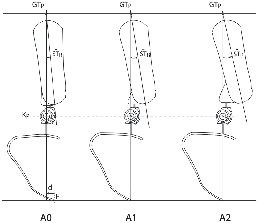
Sagittal view of three different bench alignments A0, A1, and A2.
Equipment
The athlete was asked to run on an instrumented split-belt treadmill (FTMH-1244WA; Tec Gihan, Japan), similar to that used in previous studies.20,21 The treadmill measured the three-dimensional ground reaction forces (GRFs) separately for the left and right belt, at 1 kHz.
After marking the position of GTP and KP, we collected a sagittal plane image of each prosthesis and the sagittal plane movement of the prosthetic side at 500 fps using a high-speed camera (SONY Alpha RX-II, Japan).
Three strain gauge bridges were positioned on the RPF and sampled at 1 kHz by a Somat eDAQlite (HBM, Germany), which was positioned next to the treadmill, in a location that did not interfere with running of the athlete.22,23 By extracting the position of GTP and KP relative to the foot clamp from the static sagittal image of the prosthesis, the instrumented RPF (iRPF) allowed for calculations of the knee and hip moments exerted by the GRF in the sagittal plane during the stance phase of running (Supplement 2).
Procedures
Data collection took place in a single day. First, the athlete answered the questions in Table 1, separately for A0, A1, and A2 based on her long-standing practice with the three alignments.
Questions uw3e to collect the athlete’s perceptions or the three alignments.
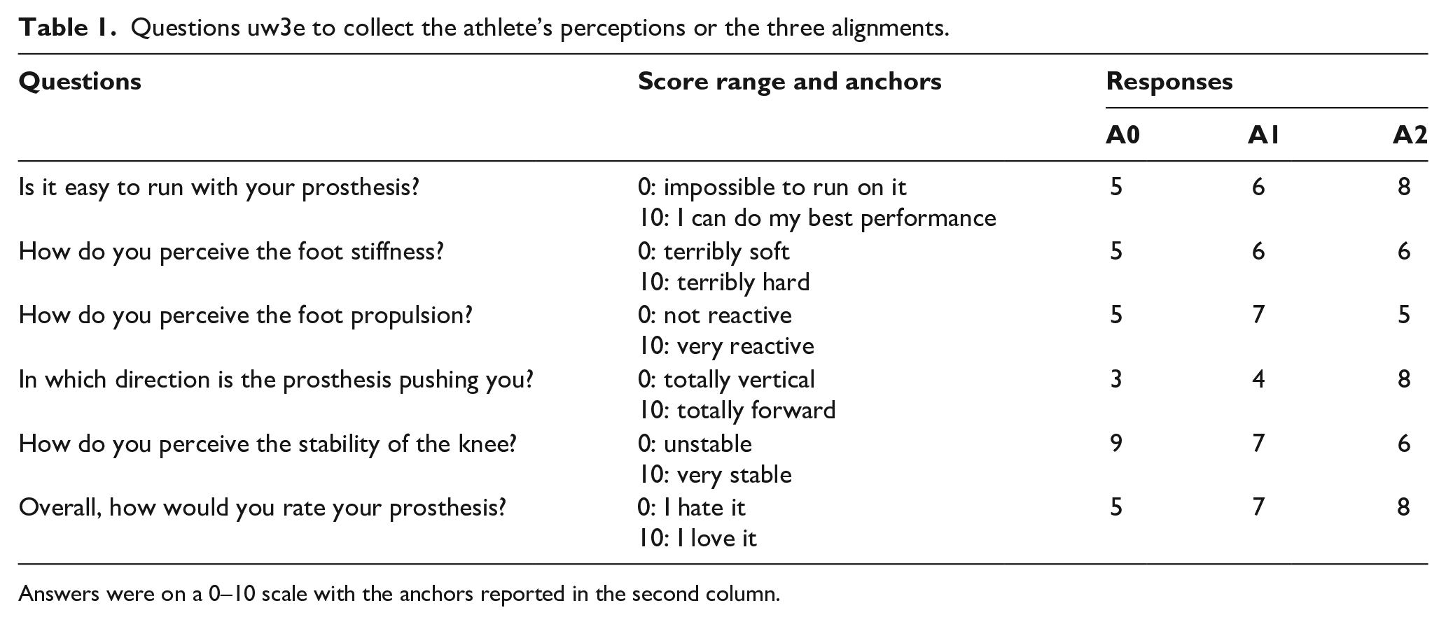
Answers were on a 0–10 scale with the anchors reported in the second column.
Then, we let the athlete familiarize herself with the treadmill while walking and running. When the athlete felt confident, we collected measurements in a morning session with A2, and in an afternoon session with A1 and A0, in this order. For each session and alignment, we recorded one trial, while increasing the treadmill speed from 0 to 5.5 m/s with a constant acceleration of 0.84 m/s 2 .20,21 At 5.5 m/s, the athlete could sustain at least seven strides per side before asking to stop; the first seven per side were considered for data analysis.
Data analysis
To assess if the socket alignment affects the kinematics of the prosthetic side, we calculated the following two angles at the instants of foot-strike and foot-off, based on the procedure described in Supplement 3):
Socket tilt
The angle between the global vertical axis and the line between GTP and F
Due to the limited buffer of the camera, the calculation was implemented for just one of the seven strides at full running speed.
Both the treadmill and the iRPF bridge signals were processed with a low-pass fourth-order Butterworth filter with a 25-Hz cutoff frequency.
We also completed the following four kinetic data analyses to assess whether A1 and A2, relative to A0:
Affected the likelihood of prosthetic knee buckling: we calculated the moment exerted by the GRFs in the sagittal plane acting at the prosthetic knee joint (MK). For the knee to be intrinsically (i.e. geometrically) safe for the athlete, MK must act in extension (i.e. positive) during the stance phase;
Changed the user’s strategy required to reach a high running speed. We investigated the step frequency, step length, and the vertical impulse of the GRF (Iv) for both sides; 24
Changed the braking and the propulsion provided by the prosthesis. Based on the horizontal component of the GRF measured by the treadmill we calculated the following:
The horizontal force impulse (Ih), separately for braking and propulsion, for the sound and the prosthetic side; The net horizontal impulse (Ihnet) for each side;
Affected the athlete’s running effort. We calculated the impulse of the moment exerted by the GRF at the prosthetic side hip in the sagittal plane (I-MH). The hip is the main power generator for patients with a TFA, therefore a decrease in I-MH was interpreted as reducing muscular effort.25,26
For these four analyses, we considered seven strides (specifically seven stance phases) per side at full speed. 21
Finally, we qualitatively compared the athlete’s scores with the biomechanical outcomes to explore if any consistency existed.
Results
Implementation of the bench alignment procedures for the test subject, resulted in an iRPF in A1 and A2 that was plantar flexed by 5° compared to A0.
The results for angles
Results for the angles
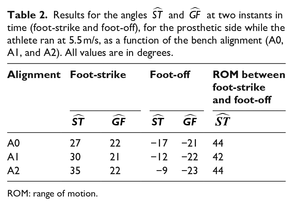
ROM: range of motion.
Figure 2 reports the mean prosthetic knee moment MK during stance, with positive values indicating extension. While the maximum knee moment decreased progressively from A0 (0.26 N m/BW), to A1 (0.18 N m/BW), to A2 (0.16 N m/BW), MK acted in extension by a large margin throughout stance. Results are presented unfiltered to provide insight into the vibrations caused by the iRPF dynamic contact on the treadmill. For all three alignments, vibrations are sensed with the same magnitude and duration by the iRPF strain gauge bridges, cross the foot up to the clamp, and reaching the knee. Vibrations quickly dampen within the initial 10% of stance, representing a marginal transient, both in terms of intensity and duration.
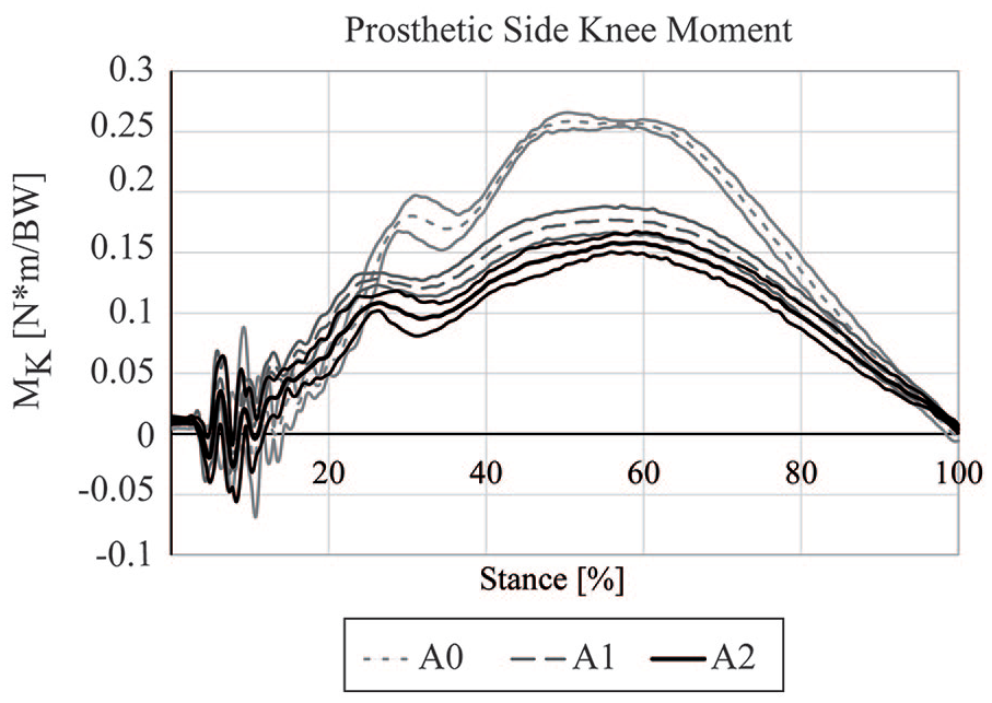
The moment acting at the prosthetic knee joint (MK) for each alignment (mean ± 1 SD). Positive values indicate a moment acting in extension, that is, an intrinsically (geometrically) safe condition for the athlete. Data are reported unfiltered, that is, as estimated from the iRPF data, which were sampled at 1 kHz.
Figure 3 reports the step frequency (Figure 3(a)), step length (Figure 3(b)), and Iv (Figure 3(c)) both for the sound and the prosthetic side. With the change in alignment, the athlete increased step frequency, reduced step length with the sound side, and reduced vertical impulse.
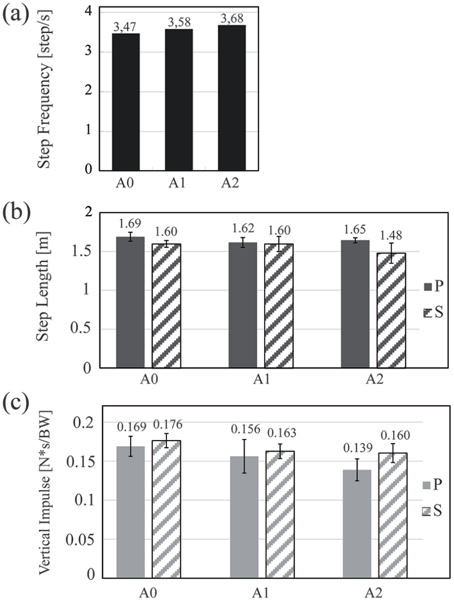
(a) Step frequency; (b) step length; and (c) vertical impulse Iv of the GRF, for A0, A1, and A2. The mean value is reported above each column. GRF: ground reaction force.
The results for Ih are reported in Figure 4. For the prosthetic side (Figure 4(a)), the braking impulse decreased when changing from A0 to A1 and A2, and Ihnet increased up to 53.6% for A2 versus A0. For the sound side (Figure 4(b)), the braking impulse increased from A0 to A1 and A2: 16.7% for A1 versus A0 and 10.0% for A2 versus A0. However, with A2, the propulsive impulse was higher than A0 and A1, and the Ihnet was negative but very close to A0. Interestingly, the magnitude of the braking impulse was higher compared to values reported in the literature for all three alignments, that is, it is likely an intrinsic feature of this athlete. 25
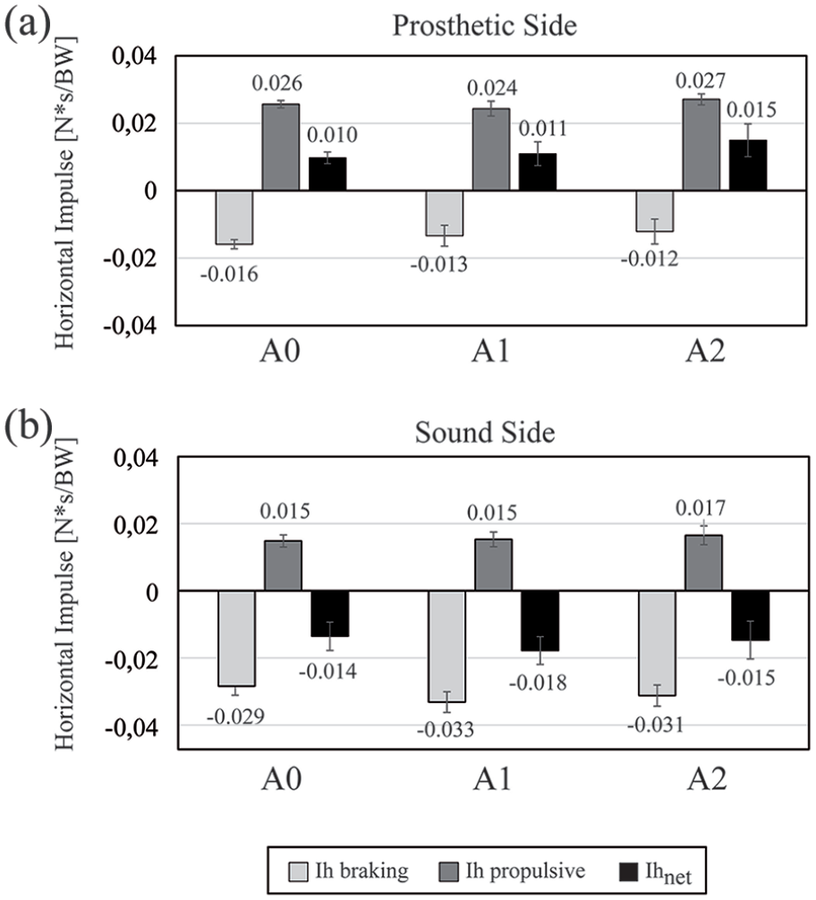
Horizontal impulses (Ih) of the GRF for the (a) prosthetic and (b) the sound side. The braking, propulsive, and net impulses are reported separately. The mean value is reported above each column. GRF: ground reaction force.
Figure 5(a) reports the running effort as measured by I-MH, which decreased from A0 to A1 to A2. The peak difference was −36.0% from A0 to A1 and −43.0% from A0 to A2.
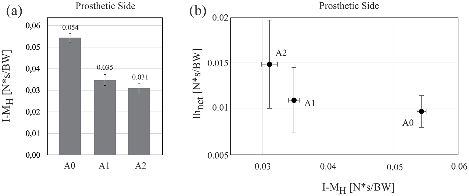
(a) The running effort as expressed by the impulse of the hip moment (I-MH), as a function of the alignment. (b) The correlation between running effort (I-MH) and the net horizontal impulse (Ihnet).
Figure 5(b) reports the correlation between the prosthetic side Ihnet and I-MH for the three alignments, showing that A2 provided two combined advantages by improving the propulsive effect of the prosthesis (Ihnet increases) and reducing the effort at the hip (I-MH decreases).
Table 1 reports the subjective scores of the athlete. Overall, A2 was perceived as the best alignment, with a score of 8/10, followed by A1 (7/10) and A0 (5/10).
Discussion
This is the first study proposing a specific bench alignment for the sprinting prosthesis of athletes with a TFA based on the biomechanics of able-bodied elite sprinters. In addition, no other studies addressed the biomechanical consequences of varying the bench alignment in such a specialized prosthesis.
The iRPF gave us the possibility to estimate the moments exerted by the GRF at the knee and hip of the prosthetic side without the need for synchronous kinematic and kinetic data. The same estimation will be possible in the field over a large number of steps and during turns. The estimation did not take into account the inertial parameters of the prosthesis because there are no validated methods available for this purpose for transfemoral prostheses, which are comprised of multiple parts made from different materials.
From the available literature,
12
the primary principle underpinning manufacturers’ recommended alignments appears to be safety of the athlete, that is, avoiding knee buckling. Our conventional alignment A0 followed the socket tilt recommended by Ottobock,
13
but the knee and foot were, respectively, 15 mm more anterior and 5 mm more posterior relative to the vertical line (i.e. more plantar flexed), to accommodate for the higher dynamic response expected from our elite athlete. Relative to A0, with A1 and A2, we increased
The kinematic analysis, despite being limited to a single stride, confirmed that the change in
The analysis of the net horizontal impulses (Ihnet) suggested that the prosthetic side with A2 is more propulsive than A0 and A1. This is remarkable because, at the same time, the muscular effort decreases, as suggested by decreased I-MH, and the hip is active in a more comfortable range as suggested by
The subjective perceptions of the athlete matched the biomechanical outcomes. Indeed, A2 was perceived as the easiest to use for running and more propulsive in the horizontal direction; the knee was perceived as stable but less than A0 and A1. Overall, the athlete perceived A2 as the best prosthesis alignment. Importantly, the week after the conclusions of the study measurements, the athlete competed internationally with the A2 alignment, and officially run the 100 m in 14.64 s, which was the second best of all times, just 0.03 s slower than the T42 World Record.
It is important to notice that the new alignment A2 was based on observations of elite able-bodied sprinters. Results suggest that this strategy led to biomechanical improvements that were perceived as beneficial by the Paralympic athlete involved in this study. However, it is important to acknowledge that the mechanics of current prostheses are substantially different from the biological leg biomechanics, generating a human system with structural asymmetries.31,32 As previously noted by Winter and Sienko, 31 a new “non-symmetrical optimal is probably being sought by the amputee within the constraints of his residual system and the mechanics of his prosthesis.” Therefore, we should refrain from assuming able-bodied biomechanics, and thus alignment A2, as “optimal” or “ideal.”
This study has limitations. First, A1 and A2 are based on the use of a uni-axial knee. However, this constraint does not have any noticeable consequence because all elite athletes using a prosthetic knee in the Paralympics since 2016 use the Ottobock 3S80 knee joint. Second, the number of able-bodied athletes observed to establish the thigh tilt at midstance was limited, despite being remarkably consistent. Third, the results are based on a single world-class athlete, running at high speed. Fourth, the kinematic analysis was based on a single stride, due to technical limitations of the equipment, and on a video analysis, which can be prone to errors. Fifth, we did not randomize the order of testing of the three alignments. We started with A2 because this was the preferred prosthesis by the athlete based on the questionnaire. Then, we proceeded from one extreme to the other among our alignments, namely, from A2, to A1, to A0, to facilitate the athlete in accommodating to the changes and being confident while running at high speed on the treadmill. Overall, our results should be used to formulate hypotheses rather than deriving generalizable rules.
Conclusion
Compared to the other two alignments and for the same running speed, A2 reduced the prosthetic side hip extension at foot-off while preserving hip range of motion, decreased the impulse of the hip moment, and increased horizontal propulsion, leaving sufficient margin to prevent knee buckling without increasing sound side braking forces.
Biomechanical outcomes appear to be highly related to the subjective perceptions of the elite athlete tested in this exploratory study. Overall, A2 appears promising to improve performance and comfort of sprinters with above-knee amputation, without compromising safety.
Supplemental Material
10.1177_0309364620946910_Supplemental_Material_1 – Supplemental material for Innovative alignment of sprinting prostheses for persons with transfemoral amputation: Exploratory study on a gold medal Paralympic athlete
Supplemental material, 10.1177_0309364620946910_Supplemental_Material_1 for Innovative alignment of sprinting prostheses for persons with transfemoral amputation: Exploratory study on a gold medal Paralympic athlete by Gian Luca Migliore, Nicola Petrone, Hiroaki Hobara, Ryu Nagahara, Kenji Miyashiro, Gian Fabio Costa, Antonio Gri and Andrea G Cutti in Prosthetics and Orthotics International
Supplemental Material
10.1177_0309364620946910_Supplemental_Material_2 – Supplemental material for Innovative alignment of sprinting prostheses for persons with transfemoral amputation: Exploratory study on a gold medal Paralympic athlete
Supplemental material, 10.1177_0309364620946910_Supplemental_Material_2 for Innovative alignment of sprinting prostheses for persons with transfemoral amputation: Exploratory study on a gold medal Paralympic athlete by Gian Luca Migliore, Nicola Petrone, Hiroaki Hobara, Ryu Nagahara, Kenji Miyashiro, Gian Fabio Costa, Antonio Gri and Andrea G Cutti in Prosthetics and Orthotics International
Supplemental Material
10.1177_0309364620946910_Supplemental_Material_3 – Supplemental material for Innovative alignment of sprinting prostheses for persons with transfemoral amputation: Exploratory study on a gold medal Paralympic athlete
Supplemental material, 10.1177_0309364620946910_Supplemental_Material_3 for Innovative alignment of sprinting prostheses for persons with transfemoral amputation: Exploratory study on a gold medal Paralympic athlete by Gian Luca Migliore, Nicola Petrone, Hiroaki Hobara, Ryu Nagahara, Kenji Miyashiro, Gian Fabio Costa, Antonio Gri and Andrea G Cutti in Prosthetics and Orthotics International
Footnotes
Appendix 1
Acknowledgements
We grateful acknowledge the essential support of Ms. Martina Caironi in performing this study.
Author contribution
G.L.M. contributed to alignment design. N.P., A.G.C., G.L.M., H.H., and G.F.C contributed to study design. H.H., N.P., G.F.C., and G.L.M participated in data acquisition. A.G.C. and N.P. helped in drafting of manuscript. All authors helped in manuscript review and data analysis.
Declaration of conflicting interests
The author(s) declared no potential conflicts of interest with respect to the research, authorship, and/or publication of this article.
Ethical approval
The National Institute of Advanced Industrial Science and Technology Institutional Review Board approved the study protocol.
Funding
The author(s) disclosed receipt of the following financial support for the research, authorship, and/or publication of this article: This study was funded by INAIL (Italian Workers Compensation Authority).
Supplemental material
Supplemental material for this article is available online.
References
Supplementary Material
Please find the following supplemental material available below.
For Open Access articles published under a Creative Commons License, all supplemental material carries the same license as the article it is associated with.
For non-Open Access articles published, all supplemental material carries a non-exclusive license, and permission requests for re-use of supplemental material or any part of supplemental material shall be sent directly to the copyright owner as specified in the copyright notice associated with the article.