
Abstract
Background:
A prosthesis that is not optimally aligned can adversely influence the rehabilitation and health of the amputee. Very few studies to date evaluate the effectiveness and utility of instrument-assisted alignment techniques in clinical practice.
Objectives:
To compare an instrument-assisted dynamic alignment technique (Compas™) to conventional methods.
Study design:
In a crossover study design, dynamic prosthetic alignments were provided to nine individuals with unilateral transtibial amputations to compare conventional and instrument-assisted alignment techniques.
Methods:
The instrument-assisted technique involved a commercially available force and torque sensing dynamic alignment system (Compas). Cadence, pelvic accelerations, and socket moments were assessed. A custom questionnaire was used to gather user perceptions.
Results:
No differences between alignment techniques were found in global gait measures including cadence and pelvic accelerations. No significant alignment differences were achieved by examination of angular changes between the socket and foot; however, significantly higher below-the-socket moments were found with the instrument-assisted technique. From the questionnaire, six amputees had no preference, while three preferred the conventional alignment.
Conclusion:
The use of Compas appears to produce similar alignment results as conventional techniques, although with slightly higher moments at the socket.
Clinical relevance
This study provides new information about the clinical utilization of instrument-assisted prosthetic alignment techniques for individuals with transtibial amputation.
Keywords
Background
Prosthetic alignment is an essential part of the fabrication and fitting process of a transtibial prosthesis. It involves three stages comprising of bench alignment, static alignment, and finally dynamic alignment, aimed at appropriately arranging the spatial three-dimensional orientation of a prosthetic socket with respect to the prosthetic foot. The goal of these alignment processes is to optimize the function of the prosthesis and improve the overall effectiveness of an amputee rehabilitation intervention to facilitate better prosthetic management outcome. 1
A prosthesis that is not optimally aligned, or considered to be misaligned, can adversely influence the rehabilitation and health of the amputee in a number of ways. Misalignment can result in imbalance of pressures and forces in the socket, and abnormal forces acting on the residual limb having adverse effects on the underlying tissues and ligaments as well as posture.2,3 Health complications associated with poor prosthetic management include skin abrasion, pain, and serious skin and joint trauma such as infection and musculoskeletal complications such as osteoarthritis.4–7 Misalignment can also result in functional limitations, including slower walking speeds, higher energy expenditure, and gait deviations such as excessive trunk and pelvic movements.8,9 Hence, in clinical practice, great care is taken in ensuring that satisfactory prosthetic alignment is achieved, and that these aforementioned problems are mitigated.
Conventionally, the prosthetist uses visual assessments of the amputee’s gait patterns, as well as relying on verbal feedback from the amputee to evaluate and improve the alignment and overall prosthetic function. While this is the accepted clinical practice, it does have a number of limitations. This approach can be time consuming and resource intensive. Furthermore, it relies largely on subjective assessments and feedback, and therefore, outcomes can be influenced by the prosthetist’s training and skills, as well as the amputee’s ability to perceive and communicate how the prosthesis is aligned and performing.10–12
In recognition of these limitations, technologies have been developed to guide prosthetists in the process of dynamically aligning a prosthesis. The most promising of these technologies are based on the measurement of loads on the lower limbs, since kinetic measures have been found to be sensitive and indicative of changes in prosthetic alignment.4,13–15 Recent advancements in sensor technologies are making it possible for load sensing instruments that can be readily incorporated within the prosthetic limb with minimal modifications to the prosthesis. 16 As the amputee walks, the system captures kinetic (force and moment) data that can then be used to provide recommendations based on realizing that more effective prosthetic treatments are achieved when kinetic gait deviations are minimized with reference to what is considered to be normal or optimal.17,18
While instrument-assisted alignment techniques have the potential to improve prosthetic rehabilitation outcomes for amputees, there is very little evidence to support their effectiveness and utility in clinical practice. The overall objective of this study was to investigate whether instrument-assisted dynamic alignment using the commercially available Compas™ system produces different alignment when compared to conventional techniques, and what effect this has on gait and amputee satisfaction. We hypothesized that the kinetic parameters (i.e. socket moments) recommended by the Compas system would be different from those achieved using conventional alignment techniques. We further hypothesized that these kinetic changes could alter the amputee’s gait characteristics including temporal measures and smoothness of gait.
Methods
Compas system
The Compas consists of an instrumented pyramid adaptor that is fitted at the distal end of the socket. It has a built-in load sensor to measure axial forces, flexion and extension moments, and varus and valgus moments, which are all defined in the instrument’s local coordinate system. The system also has a module for transmitting the data from the transducer to the computer, where the moment data are graphically presented and alignment suggestions are provided. 16 An example of the output data is presented in Figure 1. In this study, the Compas system was used both as an assistive tool in the instrument-assisted alignment technique and also as an outcome measure instrument for collecting below-the-socket moment data. Specifically, the system recorded the external peak forefoot and heel moments in the sagittal plane and varus and valgus socket moments in the frontal plane as shown in Figures 1 and 2. It is noted here that all references to moments here forth refer to external moments.
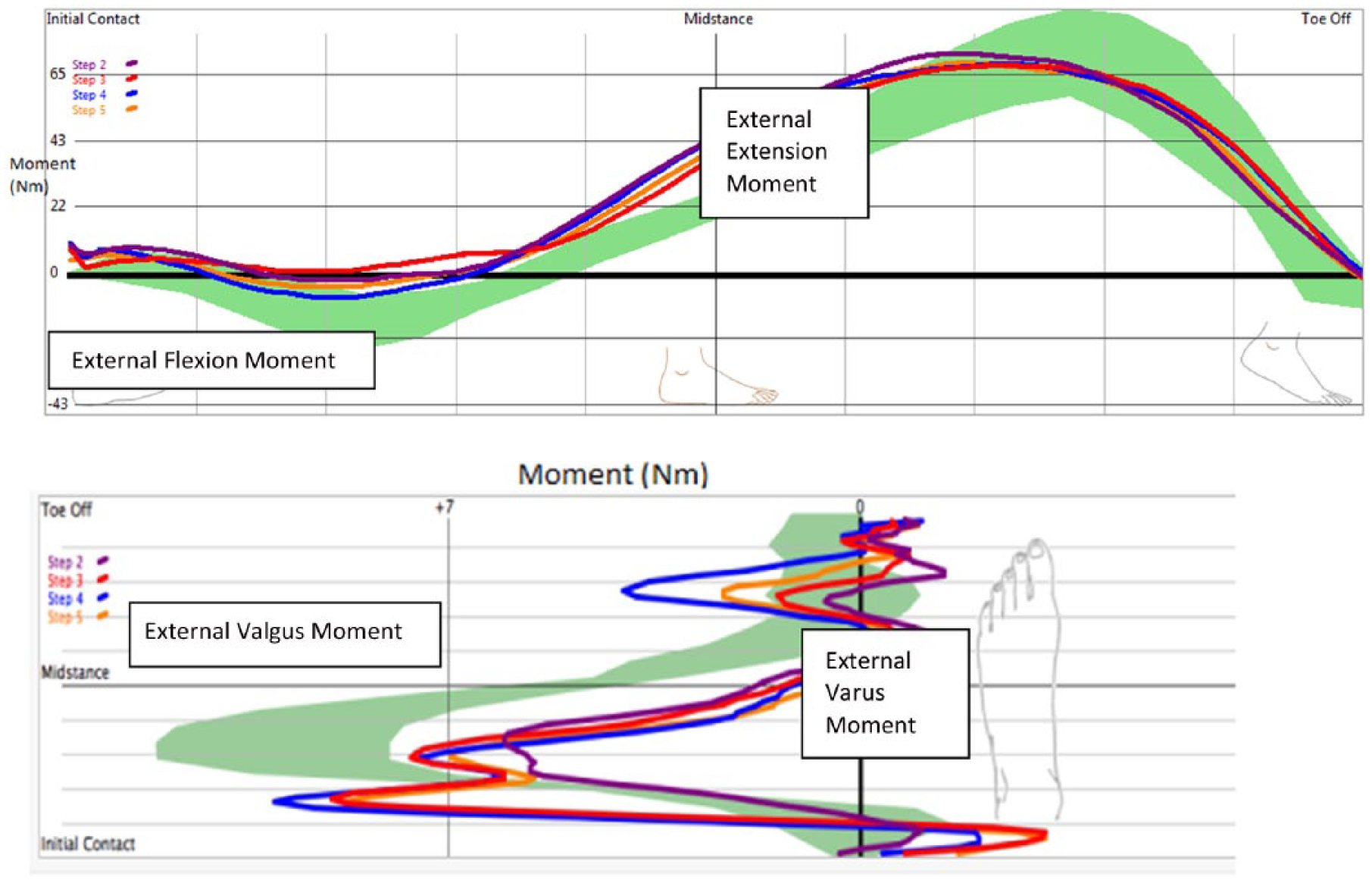
Showing output from the Compas™ system including moment data. Optimal moments are shown in green, and colored lines show sample data for four steps of a participant. Maximum flexion, extension, valgus, and varus moments are also indicated. Refer to Figure 2 for conventions.
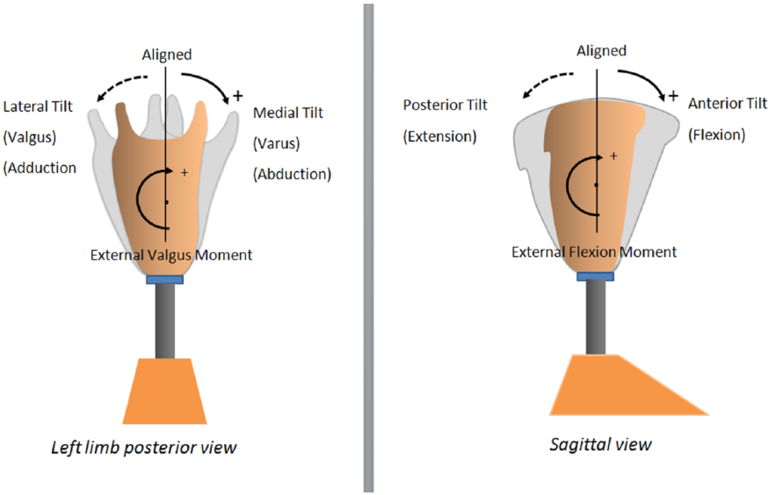
Diagrams showing conventions for alignment and external moment.
Participants
This study involved a convenience sample of nine individuals with unilateral transtibial amputation who were in the process of receiving a new prosthesis at an outpatient rehabilitation facility. Participants were established transtibial prosthetic users, 18 years or older, and using their prostheses on a daily basis in the community. Participants were excluded if they were unable to communicate in English, required additional mobility aids, or had significant comorbidities inhibiting their mobility. Participant information is shown in Table 1. The study was approved by the institution’s ethics review board, and all participants provided written consent prior to commencing with the study.
Participant demographics, BMI and LCI scores.
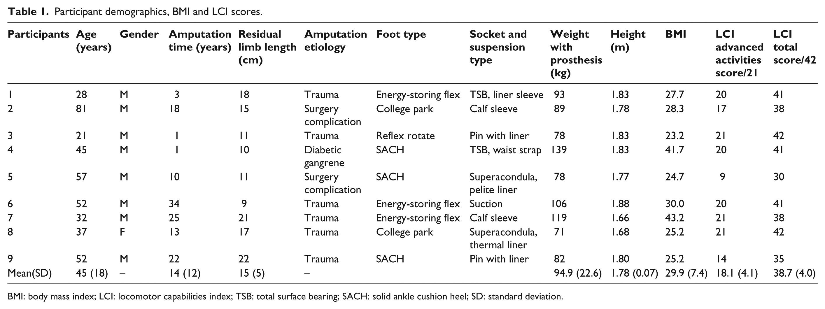
BMI: body mass index; LCI: locomotor capabilities index; TSB: total surface bearing; SACH: solid ankle cushion heel; SD: standard deviation.
Protocol
Six prosthetists were involved to perform alignments during the study visits, typically one per participant. All participants were in the process of receiving a new prosthesis into which the Compas could be applied. To ensure adequate acclimation with the new prosthesis, a minimum of 2 weeks of in-community acclimation was provided from the time of the initial fitting. During the initial fitting, conventional setup and alignment techniques were applied based on the foot manufacturer’s guidelines and standard prosthetic practices.
After 2 weeks, the participants returned to the facility for the data collections. The prosthesis was rechecked, any problems addressed, and the Compas pyramid was incorporated into the prosthesis. A crossover study design was used to test both the conventional and Compas alignments. The conventional alignment (abr. Conventional) was applied and tested first, so that the prosthetist would not be influenced by the feedback provided by the Compas. Here, conventional dynamic alignment technique was defined as the alignment of a transtibial prosthesis done by a prosthetist based on his or her expertise and subjective observation of the amputee’s gait and verbal feedback. Hence, the prosthetists were encouraged to follow their regular procedures. Once the prosthetist and prosthetic user were satisfied with the alignment, the user was given time (15–30 min) to adjust to the alignment, and measurements were taken as described in the subsequent section. Once these were completed, the prosthesis was re-aligned based on the instrument-assisted dynamic alignment technique with the Compas system. During this process, the prosthetist would follow the recommendations made by the Compas systems, until the system no longer suggested changes to be made (considered the alignment to be optimized) or in a few instances, where alignment adjustments were at the limit allowed by the prosthetic adaptors. 16 The prosthetist recorded the number of screw turns made at the pyramid while making the adjustments, so that the angular alignment difference (between the two alignment conditions) could be estimated as described below. As with the Conventional alignment, each participant was given 15–30 min to adjust.
Data collection consisted of walking trials conducted at the participant’s self-selected walking speed over a 20-m long walkway. At least three trials were collected for each alignment condition. At the end of the clinical visits, questionnaires were given to both participants and prosthetists to subjectively rate the two alignment techniques.
Instruments
To assess differences in alignments (Compas versus Conventional), the primary measure used was socket moments. Socket moments have been suggested to be highly sensitive to alignment changes as well as being related to prosthetic function, including stability during standing and walking and socket pressures.15,19 The moments were measured using the Compas system, with the adaptor fitted at the distal end of the socket. Four values (maximum flexion, extension, valgus, and varus moments) from two planes were extracted from the continuous curves as shown in Figure 1, corresponding to the peak moments occurring in early and late stance. Furthermore, the ranges of these moments were calculated for each plane, as the difference between the positive and negative peaks. Data were averaged from three consecutive steady-state steps and normalized to participants’ mass.
For the secondary outcome measures, cadence was used as a total body measure of walking function. 19 Cadence was determined using a tri-axial accelerometer 20 strapped to the pelvis at lumbar 3 (L3). 21 A sharp vertical deceleration signal corresponding to heel-strike was automatically identified using a MATLAB (MathWorks Inc., Natick, MA, USA) program, and the time between these events was determined to calculate cadence. 21
Pelvic accelerations, measured with the same accelerometer as above, were also used as a global measure of walking. 22 For each trial, data from all three axes defined as vertical, anterior/posterior, and medial/lateral were recorded. 22 Signals were filtered with a third-order low-pass Butterworth bi-directional filter, with a cut-off frequency of 20 Hz, 23 and the root mean square (RMS) values of the pelvic accelerations in all three axes were calculated according to equation (1). 24 Values were averaged over the three trials for each condition

The angular alignment changes between conditions were quantified by determining the number of turns of the set screws at the pyramid connector and calculating the below-socket angular tilt. The relationship between screw turns and angular tilt was based on tests performed on a bench top setup. The setup included the Compas male pyramid attached to a firm surface connected to a standard female pylon oriented vertically. A manual goniometer was used to quantify angular changes to within ½° as the adaptor set screws were turned. During the clinical testing, the prosthetists performed adjustments in ¼ screw turn increments (as is common in clinical practice), hence a resolution and potential error of ±½°.
To help with the interpretation of the quantitative results, two questionnaires were used to assess user and prosthetist preferences and satisfaction with each alignment. Since no suitable instruments were found for this purpose, custom questionnaires were developed with consultation of the prosthetists. The questionnaires can be found in the supplementary Appendices A1 and A2.
Analysis
To calculate the difference in alignment between the two conditions, alignment angles were set to zero for the Conventional condition, and the Compas angles (based on the number of screw turns) were subtracted and averaged across participants. The other quantitative biomechanical variables were exported and processed in MATLAB and then further prepared in Excel (Microsoft Corp., Washington, DC, USA).
The data for socket torques, cadence, and RMS accelerations for the two alignment techniques (Conventional vs Compas) were compared using a repeated measures analysis of variance. Significance was set at p < 0.05, and a Bonferroni correction was applied for multiple pair-wise comparisons. All statistical tests were performed using SPSS software, version 22 (SPSS Inc., IBM, New York, USA).
Results
A total of nine individuals with unilateral transtibial amputation participated in this study, and six prosthetists performed alignments during the study visits. Table 1 presents the details of the participants’ demographics and characteristics.
Results comparing the socket moments are provided in Table 2 and Figure 3. Table 2 shows the overall results and Figure 3 the individual trends. These include maximum flexion and extension moments in the sagittal plane and maximum varus and valgus moments in the coronal plane. These are presented as absolute values and also as ranges taken as the difference between the maximum flexion and extension moment in the sagittal plane, and the difference between maximum varus and valgus moments. The results indicate that the ranges in both planes were significantly higher, as was the maximum varus moment for the Compas versus the Conventional alignment. However, these changes in moments did not correspond to significant changes in angular alignment. In the sagittal plane, a mean anterior tilt of the socket of 1.2° (1 standard deviation (SD) = 7.2, range: −9.2 to 12.7) resulted with the Compas alignment relative to the Conventional one (p = 0.67). In the frontal plane, a relative mean medial tilt of the socket of 2.0° (1 SD = 4.2, range: −3.5 to 10.4) resulted with the Compas method compared to the Conventional alignment method (p = 0.23). Individual angular alignment changes results can be found in Table 3.
Average external peak moment variables and statistical test results.
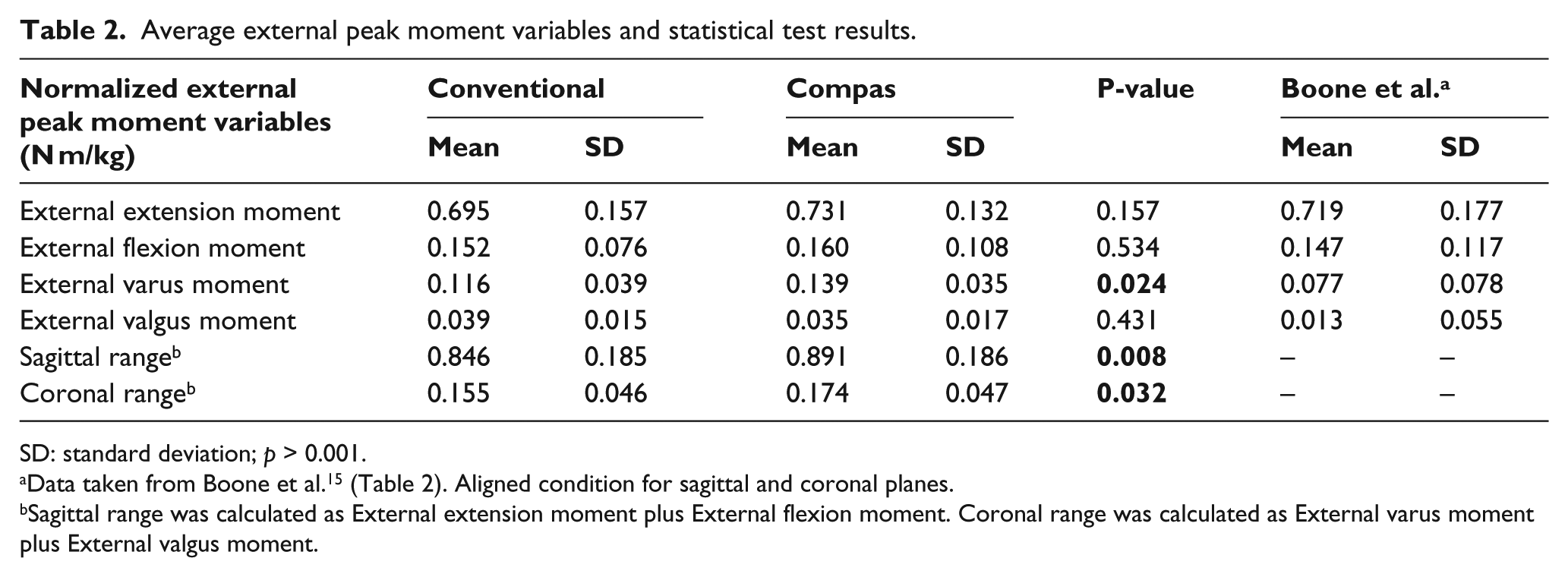
SD: standard deviation; p > 0.001.
Sagittal range was calculated as External extension moment plus External flexion moment. Coronal range was calculated as External varus moment plus External valgus moment.
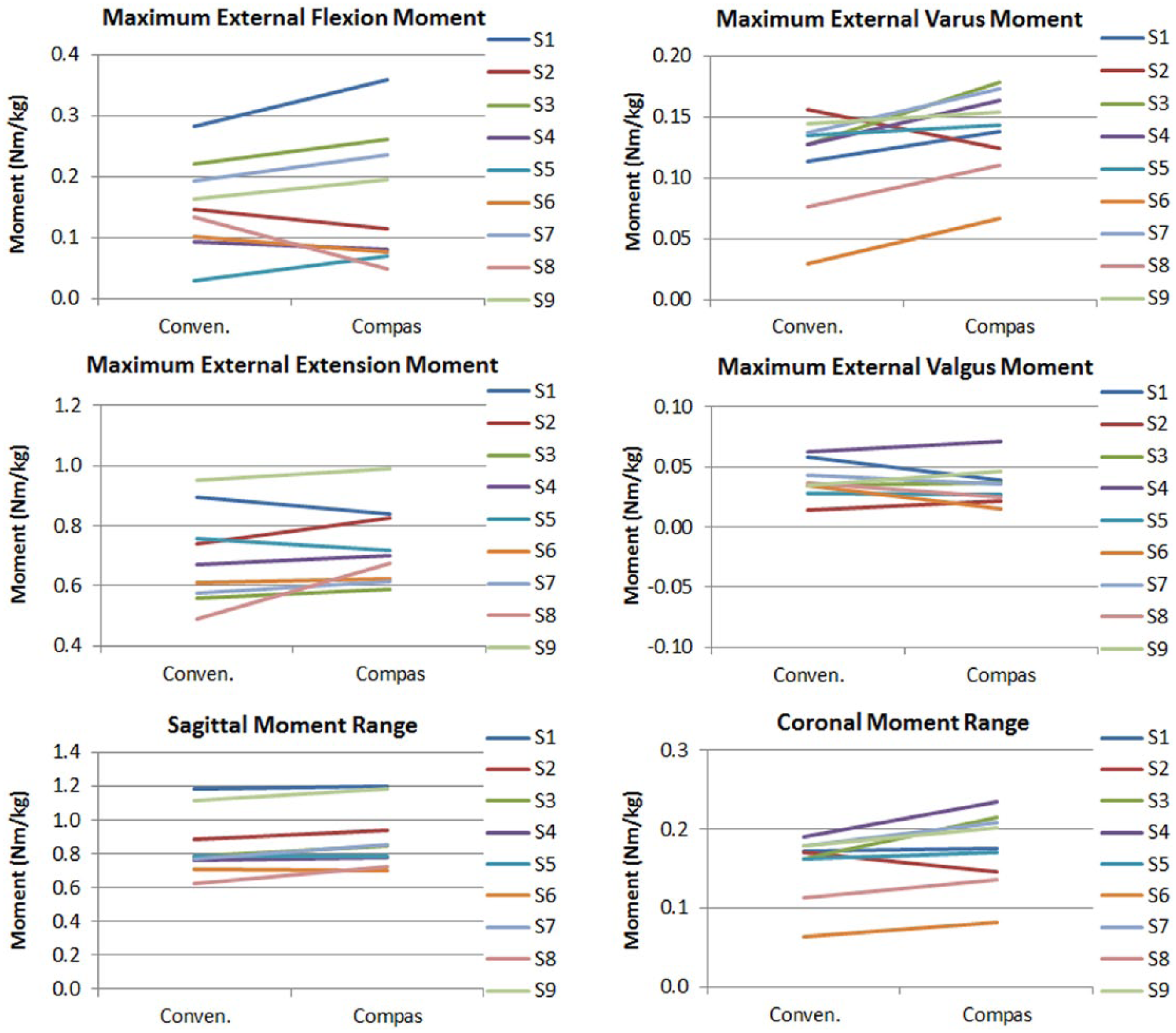
Showing individual data trends between Conventional and Compas alignment for peak external moments and ranges for participants 1 through 9.
Angular alignment change by participants.
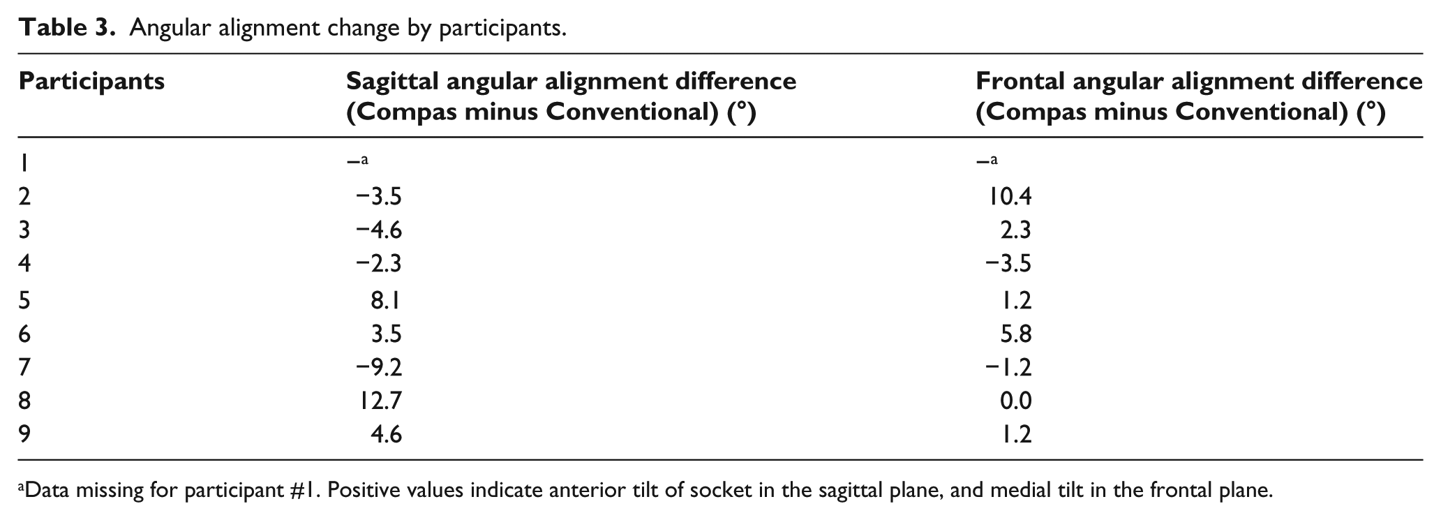
Data missing for participant #1. Positive values indicate anterior tilt of socket in the sagittal plane, and medial tilt in the frontal plane.
Cadence was found not to be affected by alignment condition. Specifically, cadence was 97.6 (1 SD = 8.4) for the Conventional alignment and 98.9 (1 SD = 9.0) for the Compas (p = 0.46). RMS pelvic accelerations were also not significant different between the two conditions. For the Conventional and Compas conditions, respectively, in the vertical direction, RMS values were 0.27 (1 SD = 0.08) m/s2 and 0.29 (1 SD = 0.13) m/s2 (p = 0.68); in the sagittal plane, they were 0.21 (1 SD = 0.09) m/s2 and 0.20 (1 SD = 0.10) m/s2 (p = 0.85) and in the frontal plane 0.20 (1 SD = 0.05) m/s2 and 0.23 (1 SD = 0.08) m/s2 (p = 0.21).
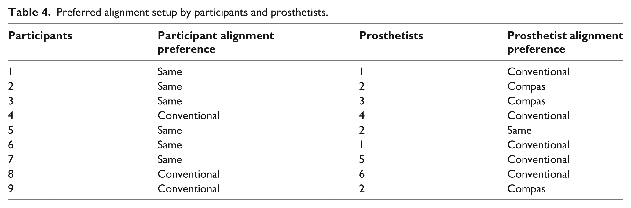
From the subjective evaluation, six out of the nine participants reported that they could not detect differences between alignment setups (Table 4). The remaining three participants (S4, S8, and S9) all indicated a preference for the Conventional alignment over the Compas. Unlike participants, prosthetists were more aware of the alignment techniques they were using during the clinical visits. Four out of six prosthetists involved in the study perceived the Conventional alignment technique to be better over the Compas technique. In general, participants and prosthetists alike preferred the Conventional technique to the Compas technique.
Preferred alignment setup by participants and prosthetists.
Discussion
Movement in the prosthetic rehabilitation professional community toward more objective and evidence-based clinical practices is urging the development of tools and techniques that can assist clinicians in this effort. Recent advancements have been made in the development of instruments to assist dynamic alignment; however, limited evidence exists to guide clinicians in the effective utilizations of these tools. This work aimed to address this gap, via an empirically based study examining the biomechanical outcomes of one such instrument, the Compas system, as compared to conventionally used prosthetic alignment techniques.
Kinetic variables have long been used as indicators of the normality of gait, and in prosthetics specifically have been found to be useful in examining prosthetic gait and function.13,15,25 In this study, significant differences in kinetic measures were found to exist between the Compas and Conventional alignments as seen in Figure 3. Overall, the Compas moment ranges (i.e. the difference between minimum and maximum moments within each plane as defined in Table 2) were significantly greater than for the Conventional alignment in both the sagittal and frontal planes by 0.045 and 0.019 N m/kg, or 5.2% and 11.9%, respectively. Furthermore, the external varus moment was also significantly greater (by 0.023 N m/kg or 18.0%) for the Compas condition. However, for both alignments, the peak moment values were found to correspond closely to those published by Boone et al. 15 (Table 2).
Given that some differences were found between the two alignment methods in terms of the moments, it is important to consider whether these might have clinical significance. In terms of the subjective preferences of the amputee participants, six of nine did not perceive a difference between the two alignments, and three preferred the Conventional alignment. Boone et al. 15 found that in the sagittal plane alignment, changes within 6° were generally not detectable by transtibial amputees, while 9° changes were. Similarly, in the coronal plane, alignment changes under 6° were not detectable. As most of the differences between Conventional and Compas alignments in this study were under 6°, the results in Table 4 appear to be reasonable, and perhaps suggestive of the fact that differences between the Conventional and Compas alignments were likely clinically insignificant for most of the participants. In other words, both alignments were quite acceptable if not within the “optimal” range for most of the participants. This appears to be supported by the fact that cadence and pelvic accelerations were nearly the same between alignment conditions.
An informal session was held at the completion of the study to ask the prosthetists of their impressions of the Compas system and its usefulness in the clinic. The main comments included that they liked the small and portable components as well as the real-time monitoring of the biomechanical moment outcomes; however, they disliked the time-consuming assembly process of inserting the pyramid into the prosthesis, and also they claimed the suggestions were inconsistent when it comes to finer alignment adjustments. Interestingly, despite these perceived inconsistencies, the resulting moments were quite similar between alignments.
A number of limitations of this study should be noted. The first limitation is a potential bias associated with the acclimation having been done on prostheses that were aligned using conventional methods, and not the Compas. This familiarization may have contributed to the participant’s preference for the Conventional alignment. As explained in the “Methods” section, this was done to prevent the prosthetist from being exposed and influenced by the Compas while doing the conventional alignment. For similar reasons, testing with the conventional alignment always preceded the Compas alignment; ideally, testing should have been randomized. The second and related limitation is that the participants were not blinded as to the alignment condition, since this would have required a much more complex protocol, including randomizing the order of testing and having different prosthetists perform the evaluation from those who performed the alignments. A third limitation relates to experience of the prosthetists in using the Compas system. While the prosthetists were provided with initial training on the use of the Compas, and they were also instructed to closely follow the manufacturer’s instructions during the study, they were not long-term users of the system. Although the Compas system is relatively straightforward to use, experience could play a role in the findings presented here. The final limitation is that the Compas instrument only makes recommendations about the angular alignment changes below the socket, and not at the ankle, whereas in practice adjustments are commonly performed at both below the socket and ankle levels. Future work should aim to control for these factors, as well as to examine the reproducibility of the procedure with Compas with the same technician, and between different technicians.
Conclusion
Determining optimal alignment based on the moments at the socket seems to have strong merit; however, more work may be needed to refine the databases that are used to drive the alignment process. While the instrument-assisted dynamic alignment technique using the Compas system resulted in slightly higher socket moments, the actual angular alignment changes were relative small, and differences were not perceivable by most of the amputees. In general, there was good agreement between the methods, suggesting the Compas may be a useful tool especially when a prosthetist may be having difficulties achieving a satisfactory alignment for their client, or less experienced prosthetists who are still developing their skills in performing dynamic alignments.
Footnotes
Acknowledgements
Thanks to Sunnybrook Centre for Independent Living (Sunny-brook Health Sciences Centre, Toronto, ON, Canada), for providing the facility and equipment for this article.
Author contribution
Caroline Chen is the main author to this article. Dr Jan Andrysek contributed to major review and editing.
Declaration of conflicting interests
The authors declare that there is no conflict of interest.
Funding
This research received no specific grant from any funding agency in the public, commercial, or not-for-profit sectors.
References
Supplementary Material
Please find the following supplemental material available below.
For Open Access articles published under a Creative Commons License, all supplemental material carries the same license as the article it is associated with.
For non-Open Access articles published, all supplemental material carries a non-exclusive license, and permission requests for re-use of supplemental material or any part of supplemental material shall be sent directly to the copyright owner as specified in the copyright notice associated with the article.