
Abstract
Background:
The fit and function of a prosthetic socket depend on the prosthetist’s ability to design the socket’s shape to distribute load comfortably over the residual limb. We recently developed a sub-ischial socket for persons with transfemoral amputation: the Northwestern University Flexible Sub-Ischial Vacuum Socket.
Objective:
This study aimed to quantify the rectifications required to fit the Northwestern University Flexible Sub-Ischial Vacuum Socket to teach the technique to prosthetists as well as provide a computer-aided design–computer-aided manufacturing option.
Study Design:
Development project.
Methods:
A program was used to align scans of unrectified and rectified negative molds and calculate shape change as a result of rectification. Averaged rectifications were used to create a socket template, which was shared with a central fabrication facility engaged in provision of Northwestern University Flexible Sub-Ischial Vacuum Sockets to early clinical adopters. Feedback regarding quality of fitting was obtained.
Results:
Rectification maps created from 30 cast pairs of successfully fit Northwestern University Flexible Sub-Ischial Vacuum Sockets confirmed that material was primarily removed from the positive mold in the proximal-lateral and posterior regions. The template was used to fabricate check sockets for 15 persons with transfemoral amputation. Feedback suggested that the template provided a reasonable initial fit with only minor adjustments.
Conclusion:
Rectification maps and template were used to facilitate teaching and central fabrication of the Northwestern University Flexible Sub-Ischial Vacuum Socket. Minor issues with quality of initial fit achieved with the template may be due to inability to adjust the template to patient characteristics (e.g. tissue type, limb shape) and/or the degree to which it represented a fully mature version of the technique.
Clinical relevance
Rectification maps help communicate an important step in the fabrication of the Northwestern University Flexible Sub-Ischial Vacuum Socket facilitating dissemination of the technique, while the average template provides an alternative fabrication option via computer-aided design–computer-aided manufacturing and central fabrication.
Keywords
Background
The fit and function of a prosthetic socket depend on the prosthetist’s ability to design the socket’s shape to distribute load comfortably over the residual limb. Traditionally, the prosthetist achieves the desired shape by either removing or adding plaster to specific regions on a positive mold of the residual limb. 1 With the advent of computer-aided design–computer-aided manufacturing (CAD–CAM), rectifications can also be accomplished by digitally manipulating either a scan of the residual limb or a scan of the negative mold of the residual limb.1–5 In either case, rectifications are performed in a manner specific to each socket design.
Since 2010, we have worked to develop a new sub-ischial socket for persons with transfemoral amputation: the Northwestern University Flexible Sub-Ischial Vacuum (NU-FlexSIV) Socket.6,7 This socket was designed to improve comfort by eliminating the proximal brim typical of ischial containment sockets, which are the current standard of care. 8 The proximal brim has been shown to significantly reduce hip motion compared to motion without a socket9,10 and lack of socket comfort is a primary complaint of prosthesis users.11–13 The NU-FlexSIV Socket combines lower trim lines with flexibility to improve comfort. Preliminary evaluation of socket use demonstrated that the NU-FlexSIV Socket improved comfort with comparable gait and functional outcomes compared to the ischial containment socket. 7
While function with sub-ischial or brimless sockets has been reported,7,14–17 only the NU-FlexSIV Socket design has been described in detail with demonstrated ability to be taught to certified prosthetists. 6 As taught through hands-on workshops, fabrication of the NU-FlexSIV Socket follows conventional steps of casting a negative mold of the residual limb and then rectifying a positive plaster mold. 6 Teaching of this technique relied, in part, on development of both a clinical algorithm that describes how to determine the magnitude and location of rectifications, and rectification maps. 6 Rectification maps, presenting difference in shape between the residual limb and the resulting socket, were first proposed by Sidles et al. 18 Using this process, the shapes of the residual limb and socket are measured and the two shapes aligned. Matching points on the surface of the residual limb and socket are identified, and the distance between them is computed. A three-dimensional (3D) picture of the residual limb with a color-coded map of the distances between each point is then created. Sidles et al. 18 proposed that rectification maps could be used to (1) teach students the rectification techniques used by successful prosthetists and compare their own attempts, (2) develop a quantitative description of methods of rectification, and (3) help develop better design tools for CAD–CAM of sockets. Rectification maps can be compared qualitatively or the shape and/or volume change quantified. The aim of this study was to quantify the rectifications required to fit the NU-FlexSIV Socket to teach the technique to prosthetists as well as provide a central fabrication option via CAD–CAM as an alternative to manual mold rectification.
Methods
Pairs of negative cast molds (NCMs) of above-knee residual limbs were collected by author R.C. as a by-product of his clinical practice. They represented the rectifications used with patients who were successfully fit with a NU-FlexSIV Socket. The University’s institutional review board approved a waiver of consent for this study because the NCMs were not directly linked to the patients they came from and were a by-product of the fabrication process. Using the method described by Sidles et al., 18 the following steps were taken to quantify the rectification process: (1) incorporated alignment markers into the positive mold, (2) created a pair of NCMs of the unrectified and rectified positive molds, (3) scanned each pair of NCMs, (4) aligned each pair of NCM scans, (5) calculated the difference in depth between each pair of NCM scans, and (6) averaged the difference in depth across pairs of NCM scans to create a rectification template. To prepare for steps 1 and 4, a custom set of three cross-shaped alignment markers were 3D printed from polycarbonate/acrylonitrile butadiene styrene (PC-ABS) plastic using a Stratasys Fused Deposition Modeler 400mc (Stratasys, Ltd, Edina, MN, USA). Two markers were 40 × 40 × 10 mm and one marker was 40 × 50 × 10 mm in dimension (Figure 1(a)).
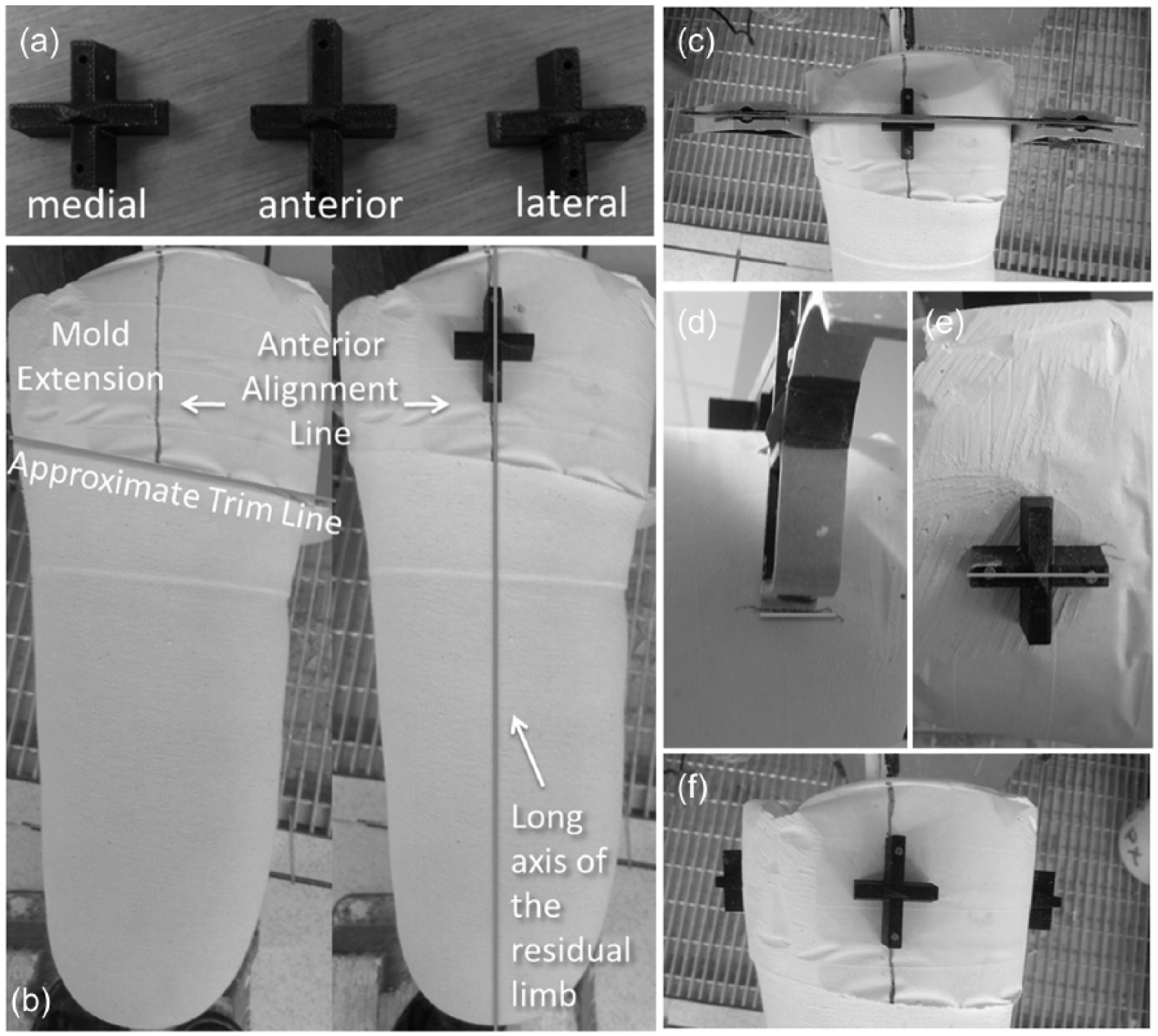
Preparation of the positive mold: (a) 3D printed alignment markers, (b) positioning largest marker on proximal mold extension in line with the anterior midline, (c–e) using carpenter’s set square to position medial and lateral markers, and (f) final position of all three alignment markers.
Incorporate alignment markers into positive mold
Standard clinical procedures were followed to create first a negative and then a positive mold of each patient’s residual limb. The negative mold of the residual limb was taken by wrapping fiberglass bandage circumferentially around the liner-clad limb as described in Fatone and Caldwell. 6 When preparing the negative mold for filling with liquid plaster, a generous extension of fiberglass or plaster bandage was added proximal to the intended socket trim line to create a proximal section in the positive mold to which alignment markers could be attached (Figure 1(b)). This extended section was not modified during the rectification process. Three alignment markers were nailed to the positive mold, proximal to the proximal socket trim line: the largest marker was placed in line with the anterior midline and the other two markers on the medial and lateral midlines (Figure 1(f)). A carpenter’s set square was used to ensure that the medial and lateral markers were placed in line with the anterior marker (Figures 1(c)–(e)).
Create a pair of NCMs of the unrectified and rectified positive molds
Prior to and following rectification of the positive mold for a NU-FlexSIV Socket, a cast sock was placed over the positive mold, and a negative fiberglass wrap of the positive mold was made that incorporated the proximal alignment markers. This resulted in a pair of unrectified and rectified NCMs for each residual limb.
Scan each pair of NCMs
Digital scans of each NCM were taken to acquire their spatial polar coordinates, which would be used to quantify the differences in shape and depth between each pair of unrectified and rectified NCMs. Rectification of the NU-FlexSIV Socket is based on a quadrant system wherein plaster is removed primarily from the lateral and posterior quadrants. 6 Hence, prior to scanning the NCMs, unrectified regions of the positive mold were colored with a black permanent marker so that they could be registered by the digital scanner. These regions included the cross-shapes of the three alignment markers and a black rectangle drawn on the distal medial wall (Figure 2). The inner surface of each NCM was then digitally scanned using a Provel d1 Digitizer (Provel, Cle Elum, WA, USA). The digital scans were processed using ShapeMaker software (S&S ShapeMaker, Hickory Hills, IL, USA) and the registered alignment landmarks labeled as follows: anterior, medial, lateral (from the three cross-shapes) and MW1, MW2, MW3, and MW4 (from the four midpoints of each side of the rectangle drawn on the distal medial wall).
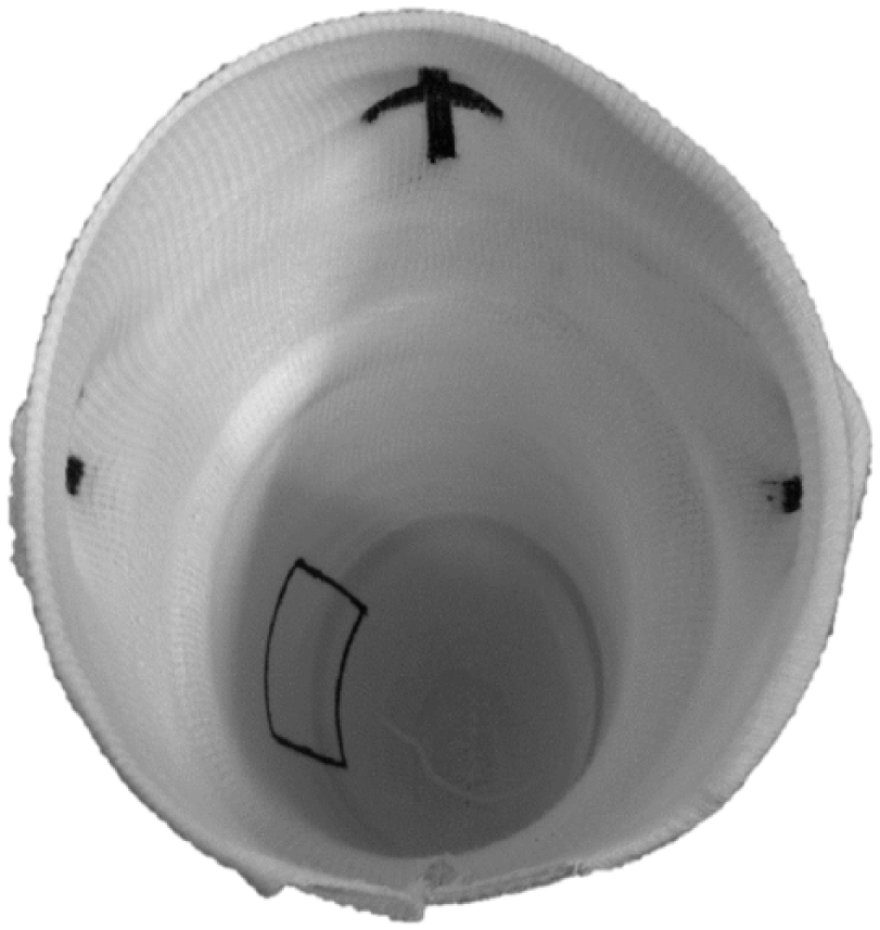
Alignment landmarks in the negative cast mold enhanced with a black marker pen to facilitate recognition during scanning into ShapeMaker software.
Align each pair of NCM scans
A MATLAB script was used to align the unrectified NCM scan and its corresponding rectified NCM scan with respect to the seven landmarks extracted in the previous step so that the corresponding unrectified regions of the scans coincided with one another. The alignment procedure began by slicing each scan along its longitudinal axis (Z-axis) and, for each slice, calculating the centroid. A linear regression was performed to find the best fit line for all centroids, which was used to define the long axis of each scan. The NCM scans were rotated and translated to align these long axes with the global z-axis. The anterior markers were then brought into alignment with the global x-axis and translated along the z-axis so that the two markers coincided. Next, four regions of commonality between the unrectified and rectified NCM scans were defined according to the positions of the landmarks: three regions were centered about the alignment markers placed proximally and the remaining region was centered about the four landmarks that defined the medial wall. These regions were used to refine the alignment using an iterative closest point algorithm19,20 (Figure 3(a)).
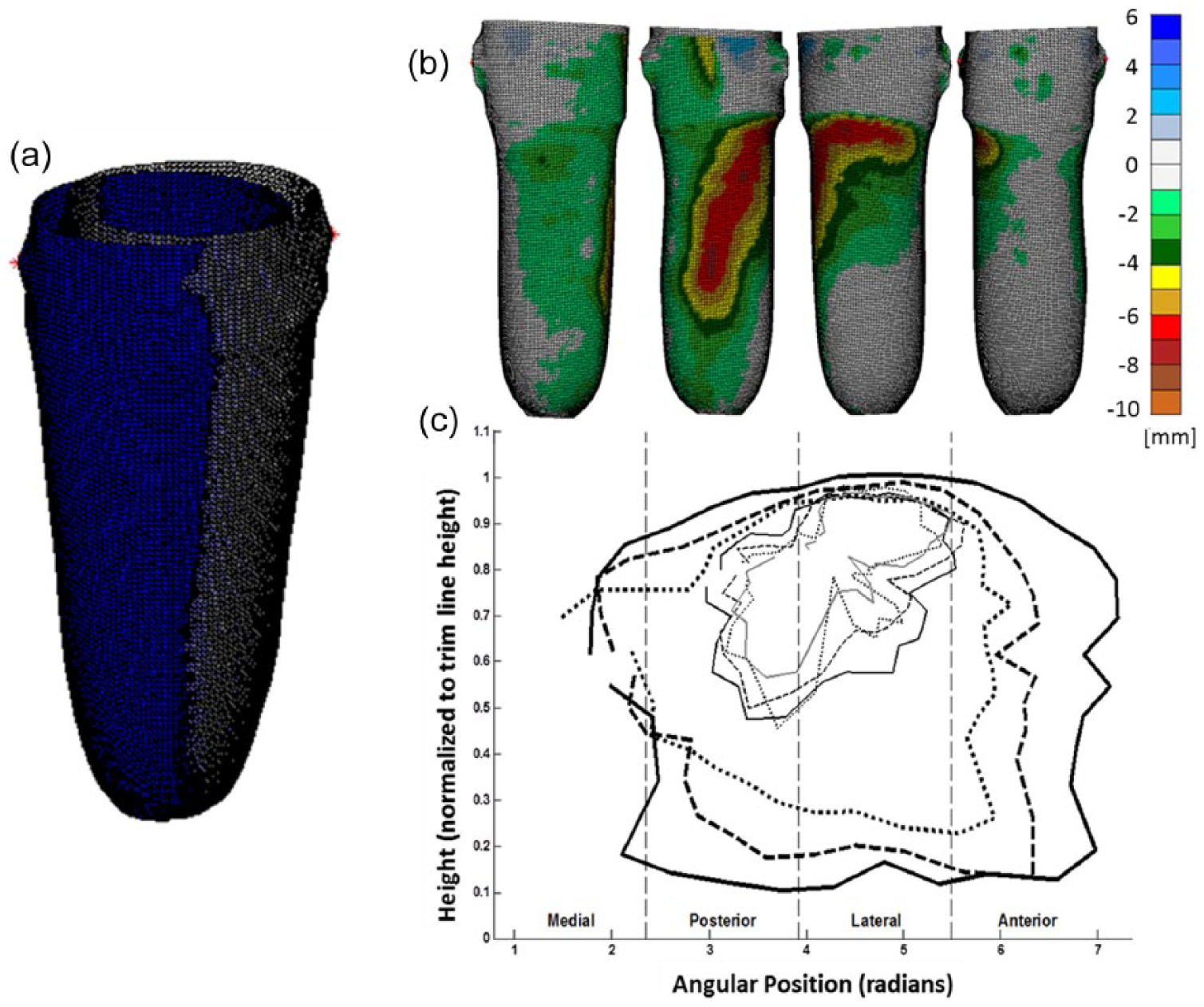
Comparison of casts before and after alignment: (a) juxtaposition of unrectified and rectified casts before alignment. (b) From left to right: medial, posterior, lateral, and anterior views of rectification map from a single representative subject. Color-coded scale indicates the difference in position (mm) of corresponding points between unrectified and rectified casts. (c) Average template depicted as the average contours from 30 casts plotted on the θ–Z plane.
Calculate the difference in depth between each pair of NCM scans
Once the NCM scans were properly aligned, a MATLAB script was used to calculate differences in the shape and depth between the unrectified and rectified NCMs. Vertices from the rectified shape were projected onto the unrectified shape along their vertex normal. The differences between scans were quantified by subtracting the vertices (rectified shape) from their corresponding projected points (unrectified shape). A color-coded scale with units in millimeters was used to indicate the depth of rectification. Negative numbers were used to indicate that plaster was removed from the positive mold, while positive numbers were used to indicate addition of plaster. However, only negative numbers were needed since the NU-FlexSIV Socket technique requires only removal of the plaster. The color-coded rectification maps for each pair of NCM scans revealed the depth and shape of the modifications that were made to each positive mold (Figure 3(b)). The outer edges of each colored region on the rectification map formed loops that we refer to as contour loops.
Average the differences in depth across pairs of NCM scans to create an average rectification template
To identify a general pattern of rectifications, another MATLAB script was used to take an average of all the rectification maps. Coordinates along the contours of the rectification maps were defined by their position along the longitudinal axis (Z) and their angular position about the longitudinal axis (θ). The Z components were normalized by the height of the trim line as measured directly beneath the lateral marker. The contours were grouped together according to their depth, arc measure about the longitudinal axis, and length along the longitudinal axis. The mean of the Z and θ coordinates for each group of contours was calculated and then subtracted from each of the coordinates to center the data. Then, following the example of Lemaire and Johnson, 3 the 3D contours were simplified by projecting them onto a two-dimensional (2D) graph with axes labeled θ and Z. This θ–Z plane was divided radially into 10° sections, and points within each section were averaged together to yield an average contour. The mean of the original group of coordinates was then added back to each of the newly averaged coordinates to place them in the original reference frame of the cast. Figure 3(c) shows the resulting average contours on the θ–Z plane.
The average template created with the above process was shared with a central fabrication facility to assess how it performed when used to fulfill requests for CAD–CAM fabrication by early clinical adopters of the NU-FlexSIV Socket following workshops held in 2015. 6 As is typical in the central fabrication of prosthetic sockets, certified prosthetists sent unrectified NCMs of the residual limb, which were then digitally scanned and rectified by the central fabrication facility using the NU-FlexSIV Socket template. 5 The template was applied in proportion to the circumference and length of the unrectified NCM digital scan. The digital scan is referenced by vertical slices with a fixed number of polar coordinates per slice. A resolution of 1.5-mm slices with 190 points per slice was used, which allowed for data points every 2°. Once the template was applied, a blending function was used to smooth out the transition between contour regions within the template. A foam positive mold was carved into the rectified shape and a diagnostic check socket fabricated and sent to the prosthetist for fitting to the patient. If necessary, modifications were made by the prosthetist to the diagnostic socket to improve fit. For the NU-FlexSIV Socket, modifications consisted of gluing foam pads to the inner surface of the proximal socket to reduce volume and/or heating and flaring the socket where increased volume or less proximal edge pressure was desired. Once the prosthetist and patient were satisfied with the fit of the diagnostic socket (with or without modifications), the socket was returned to the central fabrication facility for definitive socket manufacture. This was accomplished by scanning the inner surface of the diagnostic socket to capture the adjusted shape and carving a new positive mold from a foam block so that the definitive NU-FlexSIV Socket could be fabricated.
Results
Thirty pairs of unrectified and rectified casts were collected from patients of R.C. who were successfully fit with a NU-FlexSIV Socket as part of their clinically prescribed care. All sockets achieved total contact without any socks between the liner and socket. The color-coded rectification maps and the average template confirmed that for the NU-FlexSIV Socket, the plaster from the positive mold was primarily removed from the proximal-lateral and posterior regions (Figures 3(b) and (c)). As shown in the contour map of the average template in Figure 3(c), plaster removal was deepest in the center of the contours and gradually spread out from the center.
The average template for the NU-FlexSIV Socket was used by the central fabrication facility to create diagnostic check sockets for 15 transfemoral amputee patients ordered by five certified prosthetists. Feedback from the central fabrication facility suggested that the template provided a reasonable initial fit as typically the only adjustment made to the check socket was to add a pad to decrease the proximal medio-lateral dimension of the socket intended to improve coronal plane stability of the socket with respect to the residual limb.
Discussion
While other researchers and clinicians have begun to evaluate the performance of sub-ischial or brimless sockets,21–23 to our knowledge, no one else has yet described a technique for fabricating and successfully fitting sub-ischial sockets. 6 This study describes rectification maps and an average template specific to the NU-FlexSIV Socket to facilitate teaching and central fabrication of this socket technique.
Rectification maps such as those calculated in this study have been used to compare consistency of cast rectifications between prosthetists, 24 build CAD–CAM templates,2,3,25 and assess CAM sockets.4,5 As proposed by Sidles et al., 18 rectification maps can also be used as a tool to teach prosthetists how to modify a positive mold for specific socket designs. Additionally, Sidles et al. 18 noted that the alignment used to compute rectification maps is convention-dependent: choose the alignment that minimizes the amount of material added or removed or choose an alignment that preserves anatomic landmarks known to be invariant (e.g. the tibial crest in a transtibial socket or in our case the distal medial wall). We chose to use the latter because the NU-FlexSIV Socket requires the removal of the material in only a single contiguous rectification spanning the lateral and posterior regions.
Rectification maps of the NU-FlexSIV Socket were used as part of a series of 2-day hands-on continuing education workshops to teach certified prosthetists the rectification process required to fit and fabricate the NU-FlexSIV Socket. 6 The color-coded rectification maps depicted that the target areas for removing plaster from the positive mold are the proximal-lateral and posterior regions (Figure 3(b)). The shape of plaster removal was described as being that of a boomerang, beginning proximal-laterally and wrapping posteriorly. It was previously reported that 28 of the 30 certified prosthetists who took the NU-FlexSIV Socket courses held in summer 2015 successfully fit a check version of the NU-FlexSIV Socket on their first attempt with only minor adjustments needed. 6 Adjustments typically consisted of gluing a foam pad to the inner surface of the socket to decrease either the proximal medio-lateral dimension or the proximal anterior–posterior dimension and/or heating and flaring the medial or posterior trim line where increased volume or less proximal edge pressure was needed. Patient models were able to walk comfortably in the rigid check socket with little visual change in gait when compared to their regularly used socket.
In calculating the rectification maps and template for the NU-FlexSIV Socket, a MATLAB script was written to align digital scans of unrectified and rectified NCMs and calculate the changes in the shape as a result of rectification. Negative casts constructed from fiberglass bandage can warp and create the appearance of the changes where there actually were none. Scanning unrectified and rectified positive molds directly rather than negative casts may help simplify and improve accuracy of the alignment process. This would also avoid introducing variability during scanning from orientation of the NCM in the scanner. If digital scans were taken of a single positive mold before and after rectification, it would eliminate errors from warping and decrease the degrees of freedom for orientations from 3 to 1, simplifying the alignment process.
When rectifying manually, a clinical algorithm 6 that considers residual limb characteristics such as tissue type and limb shape is used to determine the magnitude and location of plaster removal from the positive mold, resulting in some variation across patients. The clinical algorithm helps prosthetists to choose target circumferential reductions of 6%–5%–4%, 5%–4%–3%, or 4%–3%–2%, gradated from proximal to distal. However, in developing the template for the NU-FlexSIV Socket, 30 cast pairs representing varying limb characteristics were collected and their rectifications averaged together regardless of the target reduction actually performed. Hence, when using the template, the magnitude of material removal applied digitally was exactly the same for each residual limb. It is therefore not surprising that initial experience using the average template, which applies the least circumferential reductions as part of central fabrication of the NU-FlexSIV Socket, suggested that it often underestimated the magnitude of material removal needed in the proximal-lateral region. This issue may be addressed by comparing the circumferences of the template-modified model to the original model, and adjust the circumferences based on the prosthetists’ evaluation of tissue type to better match the 6%–5%–4%, 5%–4%–3%, or 4%–3%–2% gradation suggested by the clinical algorithm. A more sophisticated template would allow the CAD–CAM user to enter patient-specific residual limb characteristics similar to those used in the clinical algorithm and auto-adjust the template to achieve a more precise fit for that individual patient.
An additional factor to consider when evaluating performance of the average template is that the 30 cast pairs used to create the initial template were collected during a period when the technique was not fully mature. Early on, the technique was likely more variable and/or less aggressive in the amount of plaster reduction than the current technique. Having taught a current version of the technique successfully, collection of additional cast pairs using the more mature technique may help further refine the average template.
Conclusion
In summary, rectification maps help communicate an important step in the fabrication of the NU-FlexSIV Socket, facilitating dissemination of the technique to other prosthetists. Rectification maps were averaged to create a NU-FlexSIV Socket template that provides a central fabrication option via CAD–CAM as an alternative to manual mold rectification.
Footnotes
Author contribution
All authors contributed to the drafting and editing of this article and approved the final version. Drafting and revision of this article was undertaken primarily by S.F., W.B.J., L.T., and R.C. K.T. contributed to section “Methods” that described the quantification of rectifications. C.M. contributed to the last paragraphs of sections “Methods” and “Results” that described the use of the template in central fabrication.
Declaration of conflicting interests
The author(s) declared the following potential conflicts of interest with respect to the research, authorship, and/or publication of this article: The authors declare that there are no conflicts of interest with the exception of authors R.C. and C.M., who are employed by Scheck and Siress Inc., the company that provided access to ShapeMaker software at no cost. Scheck and Siress also own Advanced O&P Solutions (AOPS), which was the central fabrication facility that trialed the authors’ template as part of the provision of commercial central fabrication services to prosthetists. R.C. is also an employee of Northwestern University in which capacity he was the co-developer with S.F. of the socket technique and contributed intellectually to the rectification maps and template development, as well as drafting of the article for clinical interpretation. R.C. provided all negative cast molds used in the analysis as a by-product of his clinical practice. C.M. was not involved in the study until template development was finished and shared with AOPS. He oversaw the use of the template in the central fabrication process and provided feedback on the template’s performance. The decision to submit this article for publication was made solely by the principal investigator (S.F.). Study data are stored on a password-protected computer to which authors R.C. and C.M. do not have access.
Funding
The author(s) disclosed receipt of the following financial support for the research, authorship, and/or publication of this article: U.S. Army Medical Research and Materiel Command Acquisition Activity (grant/award no. “W81XWH-10-1-0744”).