
Abstract
Background and Aim:
Prosthetic CAD/CAM systems require accurate 3D limb models; however, difficulties arise when working from the person’s socket since current 3D scanners have difficulties scanning socket interiors. While dedicated scanners exist, they are expensive and the cost may be prohibitive for a limited number of scans per year. A low-cost and accessible photogrammetry method for socket interior digitization is proposed, using a smartphone camera and cloud-based photogrammetry services.
Technique:
15 two-dimensional images of the socket’s interior are captured using a smartphone camera. A 3D model is generated using cloud-based software. Linear measurements were comparing between sockets and the related 3D models.
Discussion:
3D reconstruction accuracy averaged 2.6 ± 2.0 mm and 0.086 ± 0.078 L, which was less accurate than models obtained by high quality 3D scanners. However, this method would provide a viable 3D digital socket reproduction that is accessible and low-cost, after processing in prosthetic CAD software.
Clinical relevance
The described method provides a low-cost and accessible means to digitize a socket interior for use in prosthetic CAD/CAM systems, employing a smartphone camera and cloud-based photogrammetry software.
Keywords
Background and aim
Prosthetic computer-aided design (CAD)/computer-aided manufacturing (CAM) and rapid prototyping technologies require three-dimensional (3D) digitization of the residual limb. 1 However, prosthetists may want to work from the person’s current socket when producing a new prosthesis. If using CAD/CAM, the prosthetist would ideally digitize the socket interior; however, scanners used in current CAD/CAM systems (i.e. hand scanners and tablet scanning attachment) have difficulty scanning a socket’s interior due to the socket’s small cross-sectional area and surface contours that hide regions when scanned from the top. Dedicated socket interior scanning solutions exist but are expensive and may not be available in all prosthetic clinics. An accessible and low-cost method would help solve these issues, such as a method based on smartphone camera imaging and 3D reconstruction.
This technical note presents an efficient and low-cost photogrammetry method for digitizing a prosthetic socket’s interior. Photogrammetry constructs a 3D model by combining two-dimensional (2D) images taken from different viewpoints.2,3 This technique can be used to create a 3D digital model of a prosthetic socket’s interior for use in CAD/CAM systems, employing readily available technology such as smartphone cameras and cloud-based photogrammetry services.
Technique
Since surface contour reconstruction errors can occur when the surface is smooth and uniform, a patterned image should be introduced on the interior socket wall. Three approaches were tested for performance, ease of application, and speed of application. A digital projector was used to project a light pattern from the socket top; however, projecting light inside the socket created shadows that resulted in errors in the 3D reconstruction. The second method involved using washable pen markers to draw lines inside the socket. Although this pattering method was fast and did not have light-related problems, 3D model reconstruction from sockets made with transparent materials (e.g. check sockets) resulted in unsatisfactory results due to reflections. The third approach was the best method, where patterned duct tape was adhered to the socket’s interior. In this study, a 4.8-cm-wide duct tape with a princess pattern was adhered to the socket interior and to edges (Disney Princesses duct tape, Twenty10Licensing). This provided patterns that can be matched between images and removed reflections from shiny socket materials. Even though a specific tape pattern is presented, any patterned tape could be considered.
Once the socket is prepared, a series of overlapping pictures of the socket interior are taken. Good 3D reconstruction requires at least 60% overlap between two adjacent 2D images. 4 Based on pilot test results, 15 images were appropriate for 3D reconstruction of prosthetic socket interiors, although additional images could be taken without adversely affecting the results. Images were taken at three sets of positions (40 cm, θ, 25 cm; 20 cm, θ, 35 cm; 0 cm, θ, 55 cm) with angles of 0°, 72°, 144°, −144°, −72° on each set (Figure 1). For high contour areas, additional images of the region may be required to provide the necessary views for 3D modeling. Blurry images must be retaken (i.e. due to intermittent focus issues with smartphones). Although other procedures could be used, this method provides repeatable and accurate input for photogrammetry. As with any photography, lighting is a critical factor. 5 An area in the room where light was uniformly distributed produced the best 2D images. Non-uniform lighting reduces model reconstruction accuracy.
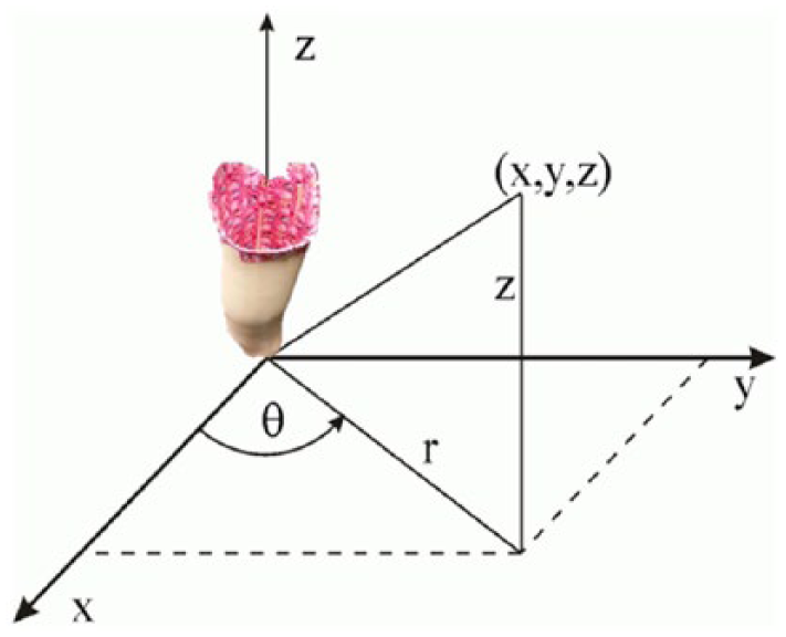
Cylindrical coordinate reference system for photogrammetric image acquisition technique.
The obtained 15 images were uploaded to photogrammetry software that combined the 2D photos into a 3D point cloud that can be edited and imported into prosthetic CAD software. Autodesk Recap 360 software 6 was used in this study to produce the 3D socket model (Figure 2). Autodesk Recap 360 is an online service that creates high-resolution textured 3D models from 2D images (i.e. 3D points and full color image that is integrated onto the 3D shape). The 3D model was uploaded to the Autodesk Memento software 7 to convert the set of 3D points into a high-definition 3D mesh, scale the 3D model to the real world, and smooth the 3D reconstruction. Memento was also used to measure distances between markers on the model (Figure 2). The free and open-source Blender 8 software was used to measure the volume of the reconstructed models.
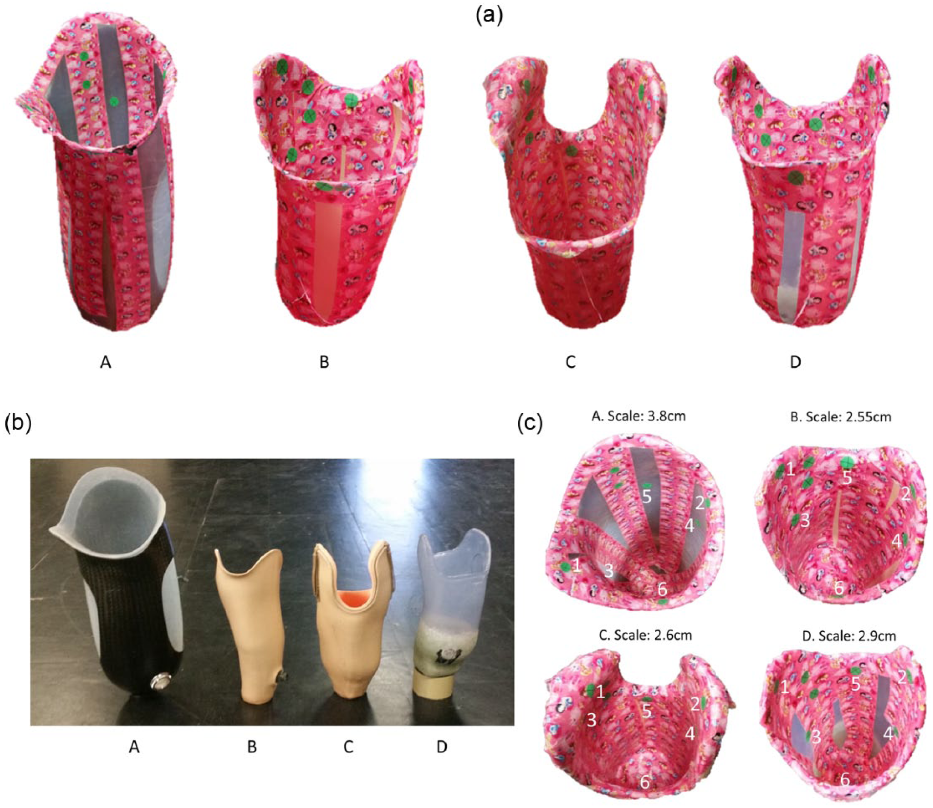
(a) Autodesk Memento reconstruction of the analyzed four prosthetic sockets after smoothing (A: transfemoral carbon-fiber socket with thermoplastic liner, B: thermoplastic transtibial socket with pin lock, C: transtibial laminated supracondylar suction socket, and D: thermoplastic transtibial check socket); (b) four prosthetic sockets for the reconstruction; and (c) markers and scale factors for each prosthetic socket.
Evaluation
Four prosthetic sockets were selected for 3D reconstruction, covering a variety of materials and sizes. These included a transfemoral carbon-fiber socket with thermoplastic liner, thermoplastic transtibial socket with pin lock, transtibial laminated supracondylar suction socket, and a thermoplastic transtibial check socket (Figure 2).
A Samsung Galaxy S5 smartphone with a 16-MP camera was used to obtain images of the socket interior. Default camera settings were used. Although a specific camera is presented, other cameras that fit inside the socket can be used for image capture. The camera was hand-held for all image captures, and one project assistant collected all study data.
To measure distances inside the socket and in the reconstructed model, six markers were added to the socket’s interior as green dots with an “X.” Measurements were from the middle of the X mark. The measured distances were as follows: (1) marker 1 to marker 2, (2) marker 3 to marker 4, and (3) marker 5 to marker 6 (Figure 2). Since the obtained 3D reconstruction was not scaled to the real world, an additional two markers were used as a linear scale factor for Autodesk Memento. A total of 15 images were used for all the sockets except for the transtibial laminated supracondylar suction socket, where an additional image was required due to the substantial curvature in one side. The extra image of the curvature was included to avoid holes in the reconstructed model.
Five trials were conducted in which each socket interior was photographed and a 3D model was produced. Three distances between markers in the socket were measured using a caliper. These distances were compared with distances measured from the reconstructed 3D model using Autodesk Memento (Table 1). This comparison assessed reconstruction accuracy and repeatability. Prosthetic socket volume was measured by filling the sockets with water up to a proximal marker. The same marker was employed in the reconstructed sockets as reference point for cropping the section proximal to the marker before measuring the distal volume in Blender (Table 2). Since socket vertical alignment was not controlled between water-filling and digitizing methods (i.e. digitized socket was manually positioned to be similar to the manual socket filling vertical alignment), small volume differences were anticipated based on the cross-sectional shape variations with differences in vertical alignment.
Difference between measurements from the socket and reconstructed 3D model (average and standard deviation), in cm.
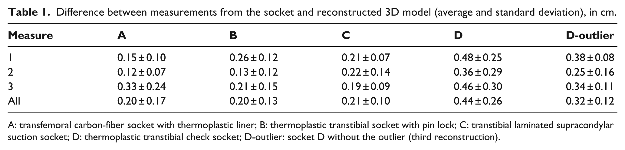
A: transfemoral carbon-fiber socket with thermoplastic liner; B: thermoplastic transtibial socket with pin lock; C: transtibial laminated supracondylar suction socket; D: thermoplastic transtibial check socket; D-outlier: socket D without the outlier (third reconstruction).
Prosthetic socket volume, average, and standard deviation for 3D model volumes, and difference between socket and reconstructed 3D models (average and standard deviation), in liters.
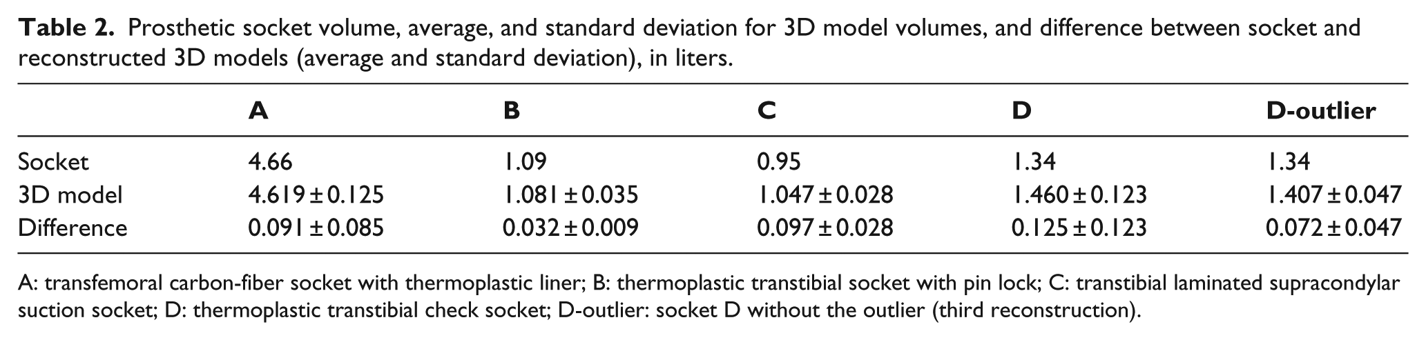
A: transfemoral carbon-fiber socket with thermoplastic liner; B: thermoplastic transtibial socket with pin lock; C: transtibial laminated supracondylar suction socket; D: thermoplastic transtibial check socket; D-outlier: socket D without the outlier (third reconstruction).
On average, the difference between the measures calculated with the caliper and measures calculated in Autodesk Memento was 2.6 ± 2.0 mm, while the volume difference between the socket and the reconstructed model was 0.086 ± 0.078 L. These results demonstrate poorer accuracy than high-quality 3D scanning systems, but the resulting 3D model would provide a viable socket reproduction after smoothing in prosthetic CAD software.
In general, reconstructed model measurements were slightly bigger than the original prosthetic socket since 90% of the measurements were larger in the reconstructed model than in the original socket. The reason for this difference could be due to user precision errors in the measurements and differences in images used for 3D reconstruction since the average standard deviation for 3D model measurements (i.e. average of standard deviations for each set of five measurements) was 1.7 mm.
An outlier was also presented for the thermoplastic check socket (third reconstruction), with a difference between socket and 3D model measures of close to 1 cm. This difference could be due to scale factor error in the Memento software since the difference was consistent between measurements. If this outlier was removed from the analysis, the average error reduced to 2.2 ± 1.4 mm and the volume average error reduced to 0.073 ± 0.054 L. A measurement check between a new 3D model and the original socket is recommended since the socket could be redigitized within a reasonable time to generate a viable 3D model for CAD modification.
The coefficient of variation of the reconstructed volume varied from 0.79% to 9.25% between models (0.79%–3.52% after removing the outlier reconstruction). The maximum results from this study are greater than other studies in the literature. 9 This discrepancy could be due to precision errors made by the user while measuring the volume as well as the 3D model reconstruction errors mentioned formerly.
The time required for taping, marking, and taking socket’s interior photogrammetric images was measured for the four sockets. Adhering the tape to the sockets interior was the most time-consuming process, with an average of 5 min, 21 s (±32 s). The whole process of taping, marking, and taking socket’s interior images averaged 7 min, 43 s (±13 s).
Discussion
In this study, a socket interior 3D digitization method was presented that used readily available smartphone cameras and cloud-based photogrammetry software to provide a viable model for use in prosthetic CAD/CAM systems. While the measurement results had lower accuracy than more expensive scanners, the approximately 2-mm accuracy would provide a viable 3D model that can be used after smoothing in prosthetic CAD software. For manual reproduction of a prosthetic socket, at least 2 mm of material could be removed when smoothing the positive mold by hand. As well, measurement differences were consistently larger; therefore, a 1–1.5 mm volume reduction in the prosthetic CAD software could be performed to easily compensate for systematic errors.
Since no humans were involved in this study, no ethical committee approval was required (i.e. de-identified prosthetic sockets were used for all measurements).
Key points
A smartphone camera can be used to obtain appropriate socket interior images for 3D shape reconstruction.
Cloud-based photogrammetry software can generate a viable 3D model that can be used in prosthetic CAD software.
The socket interior 3D model has sufficient accuracy for use with prosthetic CAD systems.
Footnotes
Author contribution
All authors contributed equally in the preparation of this manuscript.
Declaration of conflicting interests
The author(s) declared the following potential conflicts of interest with respect to the research, authorship, and/or publication of this article: Dr Lemaire is an Associate Editor of Prosthetics and Orthotics International. Review of the manuscript was managed in accordance with the Journal’s COI policy.
Funding
The author(s) disclosed receipt of the following financial support for the research, authorship, and/or publication of this article: This study was funded by the ARGO Program (grant/award no. ARGO/CA/4579) and the Global Internship Program 2015.