
Abstract
Background:
Transradial body-powered prostheses are extensively used by upper-limb amputees. This prosthesis requires large muscle forces and great concentration by the patient, often leading to discomfort, muscle fatigue, and skin breakdown, limiting the capacity of the amputee to conduct daily activities. Since body-powered prostheses are commonplace, understanding their optimal operation to mitigate these drawbacks would be clinically meaningful.
Objectives:
To find the optimal operation of the prosthesis where the activation force is minimized and the grip force is maximized.
Study design:
Experimental design.
Methods:
A computer-controlled robotic amputee simulator capable of rapidly testing multiple elbow, shoulder, and scapular combinations of the residual human arm was constructed. It was fitted with a transradial prosthesis and used to systematically test multiple configurations.
Results:
We found that increased shoulder flexion, scapular abduction, elbow extension, and the placement of the ring harness near the vertebra C7 correlate with higher gripper operation efficiency, defined as the ratio of grip force to cable tension.
Conclusion:
We conclude that force transmission efficiency is closely related to body posture configuration. These results could help guide practitioners in clinical practice as well as motivate future studies in optimizing the operation of a body-powered prosthesis.
Clinical relevance
The results from this study suggest that clinicians ought to place the ring harness inferior and to the sound side of the vertebra prominens in order to maximize grip efficiency. The results will also help clinicians better instruct patients in body posture during prosthesis operation to minimize strain.
Keywords
Background
There are two major types of upper-limb prostheses: myoelectric and body-powered. Myoelectric control utilizes neural signals from residual muscles to operate battery-powered motors in the prosthesis. 1 Compared to a body-powered prosthesis, myoelectric control requires significantly less muscle force and can reach a greater range of motion. However, myoelectric prostheses are heavy, lack intuitive control, and provide limited sensory feedback.2,3 For these reasons, a significant number of amputees still prefer body-powered prostheses. 4
Body-powered prostheses commonly employ a Bowden cable to transmit the body motion and forces generated by the flexion and abduction movements at the shoulder joint to operate a mechanical terminal device 5 (Figure 1). The most common terminal device is a mechanical gripper. Mechanical grippers are preferred over passive prosthetic hands as end effectors because they are lighter, more durable, and easier to use. Studies have shown that, compared to hooks, non-motorized hands require a larger activation force from the patient and do not yield a grip force sufficient for daily activities. 4 In addition, the mechanical work efficiencies of hooks have been proven to be much higher than non-motorized hands.7,8 Used in conjunction with a Bowden cable, hooks are also capable of providing proprioceptive feedback, responding like an extension of oneself. 9 This proprioception is a key capability of body-powered prostheses that myoelectric prostheses lack.
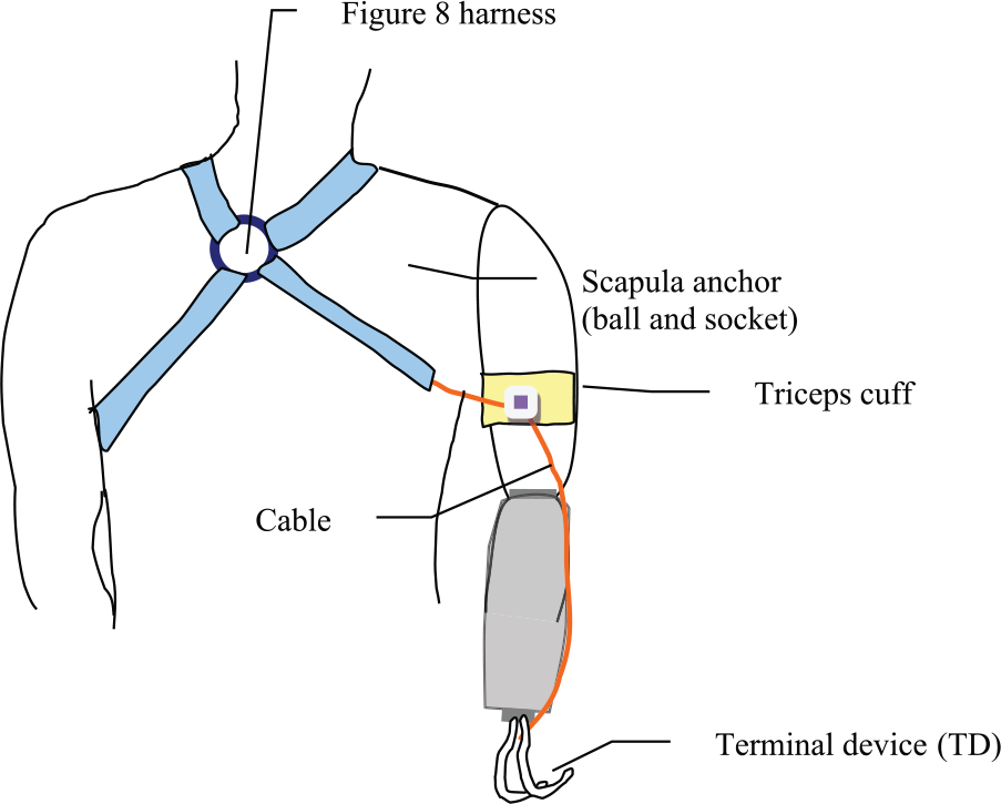
Illustration of the body-powered prosthetic simulator (posterior view). A figure-of-8 harness system for transradial amputation is illustrated.
However, large muscle forces are needed to operate a body-powered prosthesis, requiring great concentration and effort from the patient. These challenges can lead to muscle fatigue and potentially rejection by the amputee. 10 In a survey of 30 amputees and professionals in the prosthetics field, most agreed that body-powered prostheses are uncomfortable and all agreed that their function requires improvement. 11 Since body-powered prostheses are so common, mitigating these drawbacks would be clinically meaningful. Understanding the optimal operation in which activation force and strain is minimized while maximizing grip force would prove advantageous for both clinicians and amputees. Unfortunately, few studies have attempted to explore the effectiveness or optimize the operation of a Bowden cable–operated gripper.
Gao and Kapp 12 used a mechanical simulation of a transradial amputee equipped with a gripper prosthesis to explore the relationship between cable tension, cable excursion, and grip force. The aim was to determine which configurations of the harness yield the least strain on an amputee while still achieving a desired grip force. On each of the four configurations tested, the simulator had to be manually adjusted for the desired elbow, shoulder, and ring placement. This initial study was limited by the manual operation of the upper-limb simulator, which is difficult to repeat precisely and is extremely time consuming. Therefore, manually studying each of the most common configurations of the human arm is arduous, preventing more than a few configurations from being tested. An upper-limb simulator ought to have the ability to rapidly test the many possible elbow, shoulder, and scapular combinations of the residual human arm. It should also be capable of testing different types of end effectors and other body-powered prosthetic devices. This suggests that a computer-controlled robotic upper-limb simulator is needed to study the effectiveness and optimal operation of body-powered prosthetic grippers.
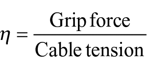
This work has two objectives: (1) develop a computer-controlled motorized simulator to mimic transradial prosthetic use and (2) systematically and quantitatively evaluate the effects of harness configuration and body posture on gripper operation efficiency. The constructed simulator is demonstrated in the video, “Upper Limb Prosthetic Simulator.” 13 During experimentation, we measured Bowden cable excursion, tension, and grip force across elbow, shoulder, and scapular positions with four ring placements. We used grip efficiency η, a ratio of grip force to cable tension, as a metric of operation efficiency
We expected that this methodical evaluation would help us establish the relationship between grip efficiency and harness configurations and/or body posture, which in turn would allow us to obtain optimal harness configurations. Elbow flexion and extension, shoulder flexion, and scapular abduction were tested for efficiency since these arm movements are involved in daily functions of reaching and grasping an object. Four ring harness positions were also tested for efficiency to verify and expand upon the conclusions of Gao et al. 12 The ring positions tested are used in current clinical practice, but they have not yet been empirically justified. By manipulating the ring position, we can find the ring’s role in the harness system, which can either challenge or support current practice. Understanding how to manipulate these variables in order to optimize the operation of this prosthetic device can help guide clinicians when fitting the harness and training their patients.
Methods
Mechanical design
The robotic simulator shown in Figure 2 was inspired by the previous design in Gao et al. We used a figure-nine harness (shown in Figures 1 and 3(a)) due to its simplicity. 14 The inner cable and housing of the Bowden cable were made of stainless steel with no liner. The simulator included actuators at the elbow, scapular, and shoulder joints, all detailed in Table 1. All motorized joints were position-controlled using a custom LabVIEW program (National Instruments, Austin, TX).
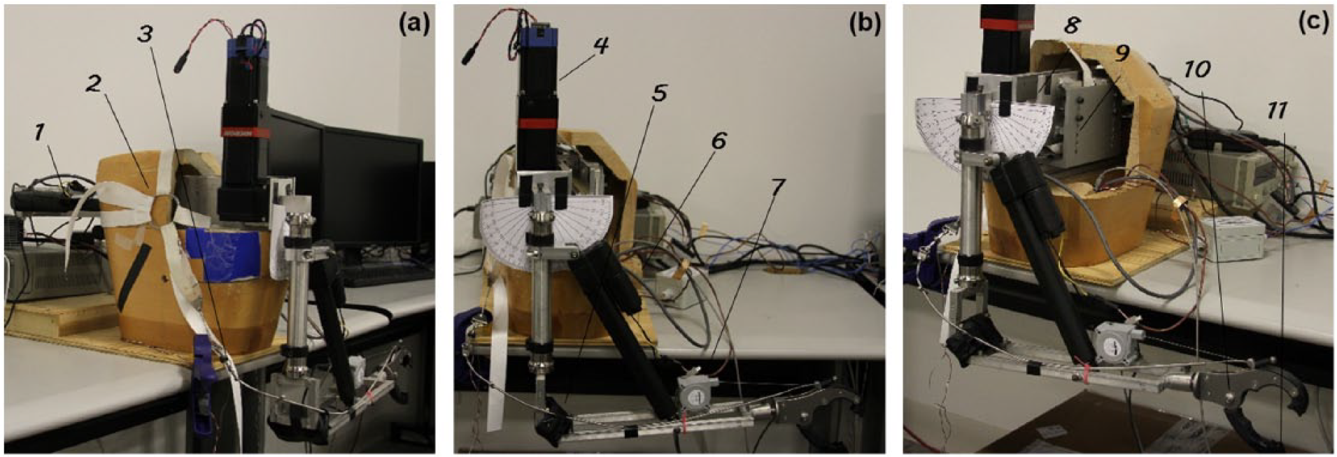
The robotic simulator viewed from (a) anterior, (b) lateral, and (c) posterior with key components labeled and detailed in Table 1.
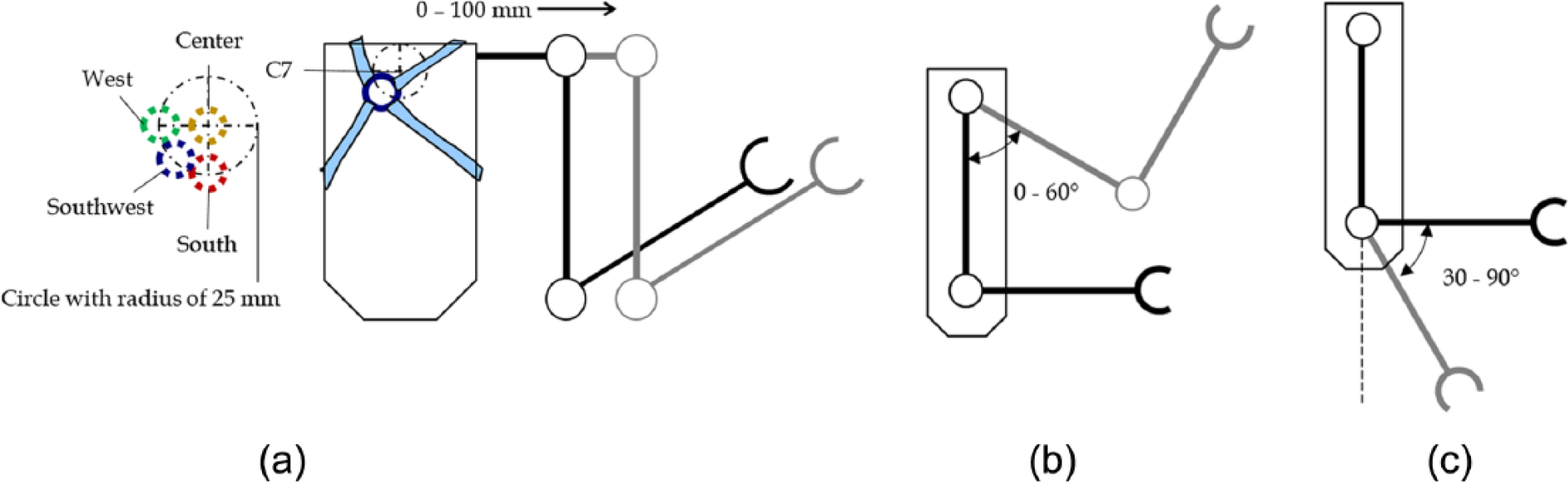
Diagrams depicting degrees of freedom that were simulated. (a) Anterior view of the simulator. It is capable of extending the scapular actuator from 0 to 100 mm. The ring harness was placed on the approximate location of C7, with each possible ring configuration labeled as shown. (b) Lateral view of simulator. Shoulder motor could flex the shoulder joint from 0° to 60°. (c) Elbow actuator could flex and extend elbow from 30° to 90° with respect to the vertical line shown.
Summary of mechanical components in simulator.
Scapula
The shoulder blade was emulated by two flat aluminum plates. One plate was mounted on the wooden manikin torso, serving as a static plate upon which the dynamic plate slides. A rail on the static plate constrained the dynamic plate to linear translation, that is, 1 degree of freedom (DOF). The dynamic plate was attached to a linear actuator (Thomson Industries, Inc., Radford, VA) with a stroke length of 100 mm and a maximum force of 225 N. This actuator enabled us to test scapular displacements from about 0 to 100 mm, enough unilateral abduction to account for the bilateral scapular abduction an amputee would typically use to operate the prosthesis. 15 We used this simplified linear design to approximate the curvilinear motion of anatomical scapular abduction by mounting the plate to the torso at an angle of approximately 23°. The gearbox and stepper motor carrying the shoulder were attached to the dynamic plate, so the entire arm would extend with the scapular plate. The motion is depicted in Figure 3(a).
Shoulder
An EvoDrive ST-23 stepper motor (EVA Robotics, Sydney, Australia) coupled with a 60:1 ratio Micron gearbox (Thomson Industries, Inc.) actuated the shoulder. The peak output torque was 108 N m, which exceeded the required holding torque of 67.8 N m for the shoulder. This enabled the shoulder to lift the entire mechanical arm even with the additional torque generated by tension on the Bowden cable. The simulator was capable of emulating the shoulder flexion shown in Figure 3(b) from 0° to 60°.
Elbow
To simulate the elbow movement, another linear actuator (Thomson Industries, Inc.) was used to extend and flex the forearm. The actuator was capable of exerting 110 N of force and extending the elbow from 90° flexion to about 20° flexion (Figure 3(c)). This design placed the side of the actuator containing the motor closest to the shoulder, reducing the moment about the shoulder.
Sensors
Three sensors were used to measure the end effector’s grip force, cable tension, and cable excursion. To measure grip force, a Flexiforce force sensitive resistor (Tekscan, Inc., Boston, MA) was used with an operational amplifier. The sensor was attached to the bottom pincer with an adhesive. A small metal disk was also placed on top of the sensor in order to provide a hard platform to focus the prongs of the top pincer onto the sensitive area of the sensor. The sensor was calibrated across the measurement range. To measure cable excursion, a linear sensor (Celesco Transducer Products, Inc., Chatsworth, CA) was attached to the same lever to which the Bowden cable was attached. When the cable pulled the gripper close, the linear sensor recorded a linear displacement from the arc that is traveled by the bottom pincer. To measure cable tension, a load cell was connected to the Bowden cable. The load cell was wired to an in-line amplifier (Honeywell International, Inc., Mansfield, TX). The three amplifiers were wired to an NI USB-6218 Data Acquisition panel (National Instruments, Austin, TX). This panel was connected to a computer with LabVIEW to assist in data acquisition.
Experimental protocol
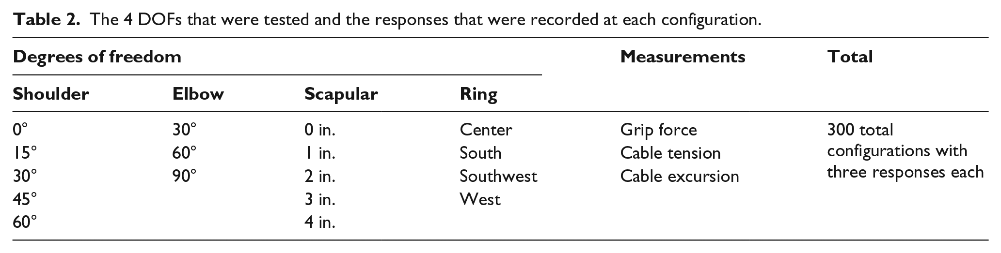
After all components, sensors, and software were connected and calibrated, the cable was anchored at the cable housing on the elbow joint and was secured on the forearm. The ring harness was anchored near “C7” (see Figure 3(a)). We focused on two aspects of the prosthesis: (1) its mechanical operation by the amputee and (2) its adjustments by the clinician. The amputee’s operation of the prosthesis consists of two primary motions: shoulder flexion and scapular abduction, which are supported by one auxiliary motion, elbow extension, when reaching. Clinicians can make adjustments to the cable housing anchor point at the elbow, the strap length, and the ring placement (see Figure 1). To avoid testing an impractical number of configurations, ring placement was chosen as the only clinical DOF in this study due to its ease of manipulation. Four different ring positions were tested as shown in Figure 3(a). The 4 DOFs (three physiological and one clinical) were meshed into 300 testable configurations as shown in Table 2. Grip force, cable tension, and cable excursion were measured simultaneously at each configuration.
The 4 DOFs that were tested and the responses that were recorded at each configuration.
To simplify operation and ensure consistency across trials, the arm movement to reach each configuration was broken down into three steps. First, the shoulder lifted or lowered the arm to the appropriate height, followed by the scapular motion and finally elbow motion to extend the forearm to the desired position.
The mesh of configurations was tested in the following order: starting at the initial position (i.e. center ring position, 0 mm scapular abduction, 0° shoulder flexion, and 30° elbow flexion), the shoulder was flexed to all desired shoulder positions. Then, the scapular position was changed and the shoulder repeated for each scapular position. Next, the elbow position was changed and the same pattern for scapular and shoulder positions was repeated. Ring placement was changed last, and the scapular, shoulder, and elbow positions were repeated in the same manner. This procedure was conducted for five trials of experimentation.
LabVIEW was programmed to collect the peak measurements of each of the three sensors only when the desired position was reached. Peak values were recorded because this study aimed to minimize patient strain and maximize gripper force. These maximal values also indicate the very moment the configuration was attained.
We also noted the configurations in which the gripper had fully closed and analyzed these key data points. Only in these configurations was it possible to examine the dynamics of cable tension versus gripper force. Grip efficiency was calculated for these specific configurations and was set to zero if the gripper was not fully closed.
Grip forces typically range from 20 to 30 N for daily activities. During experimentation, grip force ranged from 0 to 130 N, and cable tension ranged from 0 to 240 N. These forces are substantially higher than those required for daily activities because some of the configurations tested are physically unattainable by an amputee. Nonetheless, these high force configurations were tested to gain more insight into optimizing the efficiency of the prosthesis.
To account for hysteresis of the force sensor, each time a configuration that engaged the sensor was reached experimentation was paused for 1 min before moving the simulator to another configuration.
Results
Analysis of variance was conducted to determine the effects of the 4 DOFs on gripper efficiency, shown in Table 3.
Statistical values indicating if experimental results have significance and what trends are relevant.
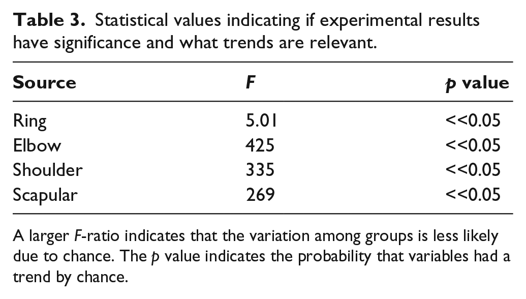
A larger F-ratio indicates that the variation among groups is less likely due to chance. The p value indicates the probability that variables had a trend by chance.
It can be concluded that all four variables had an impact on the grip efficiency of the prosthesis (p << 0.05). We next examined the specific relationship between each DOF and grip efficiency. The shoulder, scapular, and elbow DOFs were plotted as surfaces on three-dimensional (3D) spaces (Figure 4). In order to obtain a lower-dimensional visualization of the 4 DOFs versus grip efficiency, each 3D surface represents 2 DOFs versus the efficiency averaged across the remaining 2 DOFs. For example, in Figure 4(a), the efficiencies of each shoulder and scapular position were averaged across all ring and elbow positions. Standard deviations for each configuration were averaged across trials and DOFs not shown on the graph. These 3D plots show that greater shoulder flexion, elbow extension, and scapular displacement all contributed to greater grip efficiency. If we collectively call the three-arm DOFs arm extension, we can say that arm extension increased grip efficiency.
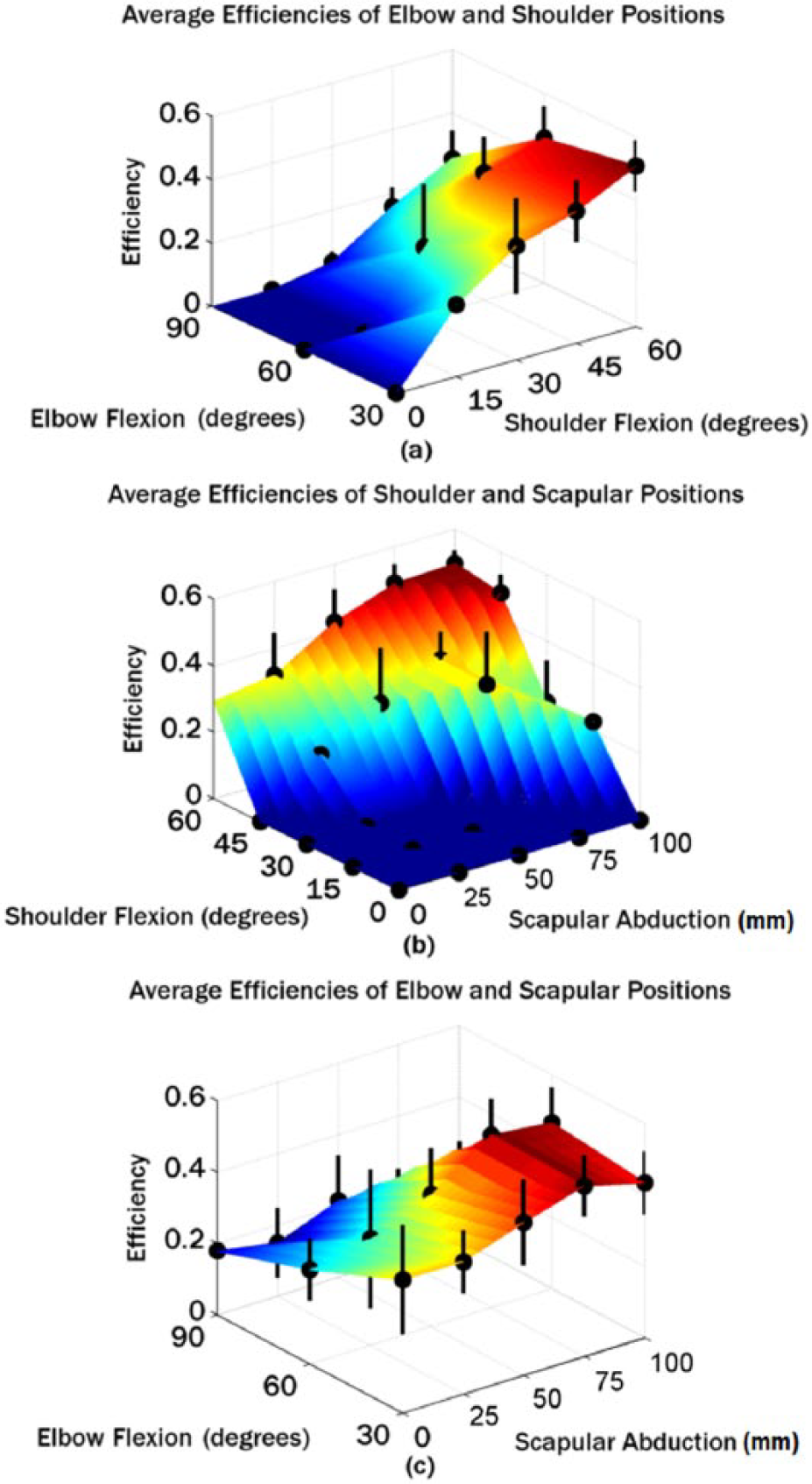
Surface plots illustrating the relationship between 2 DOFs and mean efficiency. The graph in (a) plots elbow and shoulder versus efficiency averaged across scapula and ring configurations. The graph in (b) plots shoulder and scapula versus efficiency averaged across elbow and ring configurations. The graph in (c) plots elbow and scapula versus efficiency averaged across shoulder and ring configurations.
Linear regression was performed on each variable in MATLAB to estimate each variable’s effect averaged over all other variables. The resultant bar graph in Figure 5 shows that shoulder flexion caused the greatest increase in grip efficiency. Flexing the shoulder from 15° to 60° was reported to increase mean efficiency by about 60%, which was the highest among the other variables. Ring placement had the smallest effect on efficiency, which seems intuitive since the ring placement is not a voluntary motion that operates the prosthesis. Nonetheless, since the ring can be easily manipulated by the clinician, the placement of the ring was analyzed using a multiple comparison test, in which the southwest position was determined to be the most efficient ring configuration.
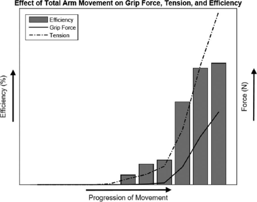
Graph depicting how grip force, tension, and efficiency change with total arm movement. As the amputee moves closer to the desired posture, efficiency slowly rises. Tension, grip force, and efficiency were taken from Southwest configurations and averaged across all trials.
Discussion
We were able to show that shoulder flexion, scapular abduction, and elbow extension contribute to the efficiency of the prosthesis. The outcomes may be helpful for clinicians to train their patients. One drawback, however, is that we could not identify a global optimal configuration using the current setup primarily due to its decoupled control and limited range of motion especially at the elbow.
The efficiency could be related to the curvature of the Bowden cable. One study reports that increasing the bend of the cable decreases the efficiency of the prosthesis. 16 This is due to frictional losses, which have been found to amplify with greater bending. 17 Thus, when the shoulder flexes, the scapula abducts, the elbow extends, or the ring placement is changed, any reduction in cable bend minimizes frictional losses and maximizes efficiency. Another study has published similar results, in which the efficiency falls with increasing wrap angle. 18 Although this study defines efficiency as the ratio of cable tension at the prehensor to the cable tension at the harness, gripper force is closely related to prehensor cable tension and the results can be compared.
Our findings also suggest that the Southwest position yields the greatest efficiency. It is worth mentioning that this result differs from the results in Gao et al., in which the most effective ring placement was closest to the C7. However, this study tested more comprehensive configurations, likely suggesting a more robust result.
Based on these results, the following clinical guidelines could be recommended:
The ring should be placed inferior and to the sound side of the vertebra prominens (C7) to induce the greatest grip efficiency. Further studies would be necessary to test more ring locations and determine the optimal distance from C7.
The shoulder harness for the amputee can be tightened to the patient’s liking. This is because the same positive correlation between efficiency and shoulder flexion/scapular abduction/elbow extension can still be seen when the harness is tightened. The only change is that less cable excursion is required to engage the terminal device.
Amputees should engage primarily the shoulder muscles and the scapula when using the prosthetic gripper in daily activities.
Clinically, the priority is to ensure comfort and ease while operating a body-powered prosthesis. Since this study used a robotic simulator to emulate human movements that can vary between individuals, the findings may not generalize to all patients. Although the robotic simulator is capable of capturing the major arm movements, one limitation is the lack of soft tissue, possibly causing outcomes to slightly deviate from those of a human amputee. Additionally, some DOFs of the human arm that were not incorporated in the simulator could be included in future studies, such as shoulder abduction. Nonetheless, the conclusions of this study serve primarily as a general overview of the mechanics of a Bowden cable–operated gripper prosthesis that can be used to suggest clinical guidelines.
Conclusion
The relationships between body force and grip force observed in this study could improve clinical practice and patient operation of body-powered prostheses that are still widely used today. The robotic upper-limb simulator presented in this work can also be used to test many other variables. For instance, how can movement velocity affect the cable-gripper dynamics? Does the location of cable housing affect efficiency? Perhaps the most important question that needs exploration is whether the results of this study can be successfully translated to human subjects. Transradial amputees could be asked to operate a body-powered prosthesis and conduct sample daily activities, such as getting coffee from the overhead cabinet or drinking a glass of water. Tension, force data, and subjective input could be collected to determine whether the suggested guidelines are helpful. A mechanism to better simulate the curvilinear motion of the human shoulder blade could also be explored. Adjustments to the robotic simulator would be necessary, or an improved model could be constructed. Future simulators may be able to engage motors and actuators simultaneously, moving the elbow, shoulder, and scapula synchronously in a coordinated motion as in a human arm. Our hope is that these studies will result in new clinical guidelines to optimize the operation of body-powered prostheses and improve the quality of life for upper-limb amputees.
Footnotes
Acknowledgements
Sincere appreciation goes to Pritam Shah, Brad Cochran, and Bharadwaj Anantha for designing and constructing the transradial amputee simulator for their undergraduate senior design project. The authors thank them for their hard work and effort.
Author contribution
All authors contributed equally in the preparation of this manuscript. R.A. wrote a majority of the manuscript and ran all experiments. D.V. guided R.A. during experimentation and reviewed many drafts of the manuscript. R.D.G. also reviewed many drafts of the manuscript and funded the project. F.G. was the principal investigator and guided the construction of the robotic simulator used in the experiments. He also reviewed many drafts of the manuscript.
Declaration of conflicting interests
The author(s) declared no potential conflicts of interest with respect to the research, authorship, and/or publication of this article.
Funding
The author(s) disclosed receipt of the following financial support for the research, authorship, and/or publication of this article: This work was partly supported by American Heart Association (Grant/Award Number: 09SDG2080460) and UT Academy of Health Science Education Small Grants. Robert D. Gregg holds a Career Award at the Scientific Interface from the Burroughs Welcome Fund.