
Abstract
Recent work suggests that a prosthetic ankle-foot component's roll-over shape – the effective rocker it conforms to between initial contact and opposite initial contact (the ‘roll-over’ interval of walking) – is closely linked to its final alignment in the prosthesis (as determined by a skilled prosthetist using heuristic techniques). If true, this information may help to determine the appropriate alignment for a lower limb prosthesis before it is built, or a priori. Knowledge is needed for future models that will incorporate the roll-over shape including the relative effect of alignment on the roll-over shape's radius of curvature and arc length. The purpose of this study was to evaluate the hypotheses that: (i) Changes in prosthesis alignment alter the position and orientation of a foot's roll-over shape in prosthesis-based coordinates, and (ii) these changes occur without changing the radius of curvature or arc length of the roll-over shape. To examine the hypotheses, this study examined the effects of nine alignment settings on the roll-over shapes of two prosthetic feet. The idea that alignment changes move and rotate roll-over shapes of prosthetic feet in prosthesis coordinates is supported by this work, but the hypothesis that the radius of curvature and arc length do not change for different alignments is not strongly supported by the data. A revised approach is presented that explains some of the changes to the roll-over shape parameters due to changes in rotational alignment.
Keywords
Introduction
Alignment of lower limb prostheses is the position and orientation of components in the prosthesis with respect to one another and the user's body. While it is clear that alignment of prosthetic components is important for good function (Hannah et al. 1984; Zahedi et al. 1986), a detailed understanding of alignment based on mechanical features of components does not exist. Such an understanding would be useful and would likely lead to improvements in lower limb prosthesis fittings worldwide. Also, a detailed understanding of the alignment process could lead to a priori alignment procedures, allowing the alignment process to be based on scientific principles instead of heuristics, and potentially eliminating the need for expensive and heavy alignment hardware. These procedures could also be taught in areas of the world that have a lack of skilled personnel to perform the current trial-and-error process.
The prosthesis alignment problem is multi-faceted. There exist several degrees of freedom in even the simplest leg prostheses. For example, a trans-tibial prosthesis has six degrees of freedom describing its alignment (i.e., three rotations and three translations describing the foot's position with respect to the socket). Also, there are many different foot components available for use in leg prostheses as well as several socket designs. Because of the many factors associated with prosthesis alignment, it is likely that modeling will be needed to gain an understanding of the process. Patient testing could be used to verify a subset of the modeling, but could not practically be used to test all possible conditions of alignment.
One important aspect of any lower limb prosthesis alignment model is the prosthetic foot. There are many commercially available foot components, most of which actually replace the ankle-foot complex. The ankle-foot roll-over shape, which is the effective rocker shape that the ankle-foot system conforms to between initial contact and opposite initial contact (the ‘roll-over’ interval of walking), is a simple way to represent the function of a prosthetic foot during this period of gait (Hansen et al. 2000). Also, recent work on trans-tibial alignment suggests that the roll-over shape of a prosthetic foot is important in the determination of optimal alignment by the prosthetist (Hansen et al. 2000, 2003; Hansen 2002). In general, prosthetists appear to align different kinds of prosthetic feet (having different roll-over shapes) toward a similar rocker shape, perhaps an ‘ideal’ rocker for the prosthesis user. The use of roll-over shapes to describe the function of prosthetic feet can simplify walking models aimed at testing effects of feet and alignment (Srinivasan 2007; Srinivasan et al. 2008; Srinivasan et al. [in press]).
There are essentially four features of a roll-over shape: Radius of curvature, arc length, position, and orientation. The first two aspects (radius of curvature and arc length) are highly linked with the mechanical design of the prosthetic foot. For example, a compliant foot will deform to a smaller radius of curvature than a stiff foot under similar loading conditions. Also, the length of the keel within the prosthetic foot will affect the arc length, or the effective foot length, of the component (Hansen et al. 2004a). The last two aspects (position and orientation of the rollover shape) are linked directly to the alignment of the prosthetic foot. The simplest model using the roll-over shape assumes that radius of curvature and arc length are related to design only and not alignment, i.e., that these two features are independent of the alignment. This assumption allows the roll-over shapes of feet to be measured in one alignment and for these shapes to be simply moved and rotated about in the alignment modeling routine. Therefore, this paper examines the hypotheses that: (i) Changing alignment of a prosthetic foot changes the position and orientation of the foot's roll-over shape, and (ii) these changes occur without appreciably changing the radius of curvature or arc length of the roll-over shape. If supported, this approach would simplify efforts to model alignment effects on gait of prosthesis users because fewer tests of prosthetic feet would be needed as input to the modeling routines.
Methods
Two prosthetic feet were used in the study: A Kingsley Solid Ankle Cushioned Heel (K-SACH) Prosthetic Foot and a Freedom Innovations Highlander Prosthetic Foot. Both feet were size 27 cm. The Highlander Prosthetic Foot had a numerical code for keel stiffness of ‘4’. These two feet were chosen because they have very different mechanical properties. These mechanical differences are illustrated in their neutral alignment roll-over shapes (Figure 1). The Highlander has a nearly circular roll-over shape, while the K-SACH has a roll-over shape that is relatively flat (i.e., large radius) from hind to midfoot and that curls up in the forefoot (i.e., it has a smaller radius at the end of the roll-over shape). An Otto Bock 4R103 Sliding Adapter was connected to a long pylon and a weight as shown in Figure 2. Reflective markers were placed on a plastic plate connected between the tube clamp portion of the Sliding Adapter and an aluminum disc at the distal end of the pylon. Two markers on the plate were placed along the midline of the prosthetic foot (shown in Figure 2) and a third was placed laterally on the plate (view of this marker is blocked by the pylon in Figure 2). When the foot was neutrally aligned, the three markers on the plastic plate defined a plane that was parallel to the attachment surface plane.
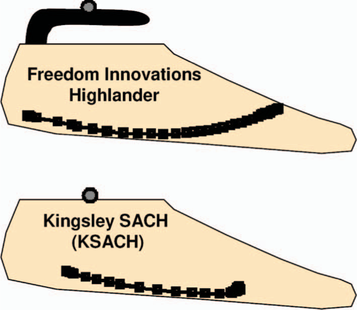
Estimated outlines of prosthetic feet and their measured roll-over shapes when tested in a neutral alignment.
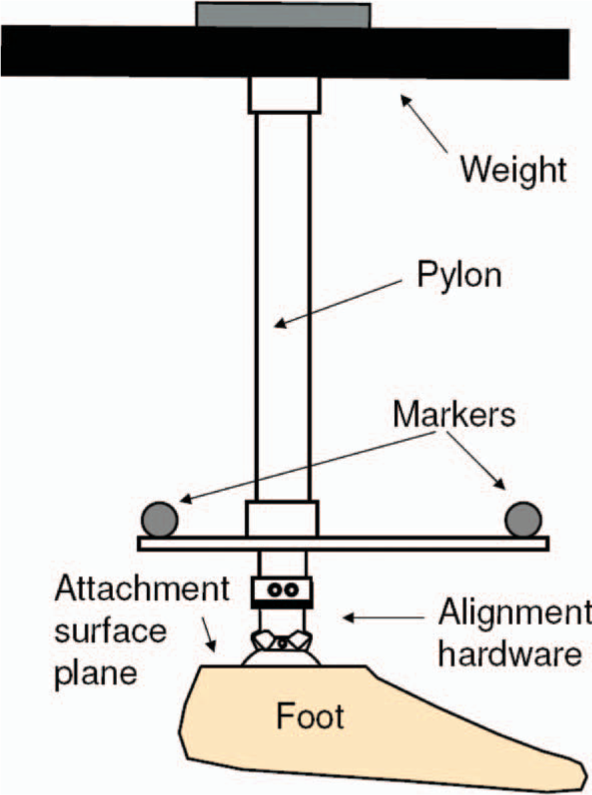
Apparatus used to test the prosthetic feet in the study. The feet were rolled over from heel to toe on a force platform using this device (as described in Hansen et al. 2004a). The alignment hardware is capable of anterior posterior shifts and dorsiflexion-plantarflexion rotations of the foot.
The roll-over shapes of each foot were determined with the feet in nine different alignments as shown in Figure 3. These values were chosen to cover the extremes of alignment possibilities available with the particular sliding adapter used in the study. To measure the roll-over shapes, the feet were rolled over an AMTI (Advanced Mechanical Technology, Inc., Watertown, MA, USA) force platform (from heel to toe loading). During the rolling motion, the technician conducting the test applied additional load such that the net load to the prosthetic foot matched a goal force level of 750 Newtons (based on the body weight of persons that would use these feet). Marker positions were tracked using an eight camera Motion Analysis Corporation (Santa Rosa, CA, USA) measurement system. This quasi-static roll-over shape testing method is described in Hansen et al. (2004a). The method's accuracy has been explored by testing a rigid rocker foot. The roll-over shape overlaid on a picture of the rigid rocker foot confirmed that the method is accurate (i.e., the roll-over shape matched the curvature of the rigid rocker's plantar surface). The method is also very repeatable. In three loading tests of the Highlander foot, the standard deviation in the X dimension of the roll-over shape was less than 3 mm and was less than 1 mm in the Y dimension.
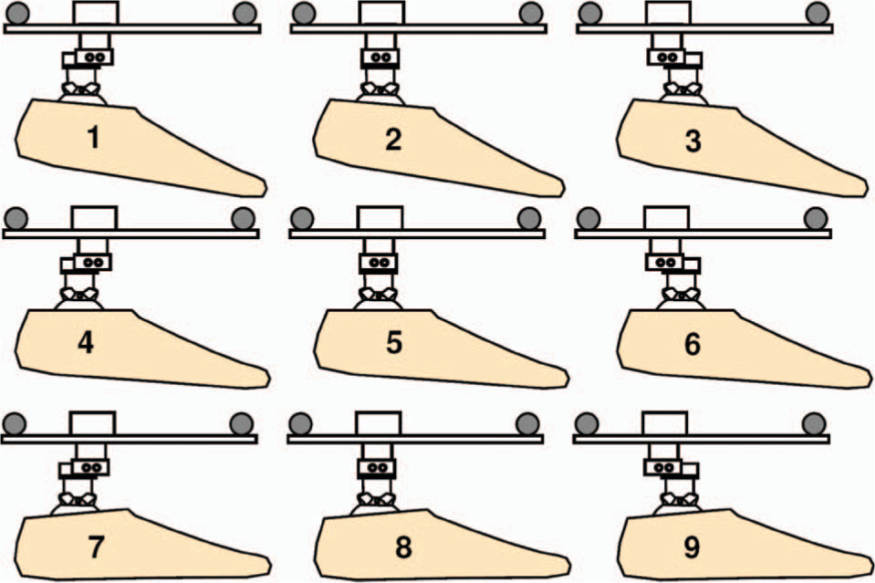
Nine alignment conditions that were used to test each of the two prosthetic feet in the study: (1) Plantarflexion 5°; Posterior shift 12 mm, (2) Plantarflexion 5°; No shift, (3) Plantarflexion 5°; Anterior shift 12 mm, (4) Neutral angle; Posterior shift 12 mm, (5) Neutral angle; No shift, (6) Neutral angle; Anterior shift 12 mm, (7) Dorsiflexion 5°; Posterior shift 12 mm, (8) Dorsiflexion 5°; No shift, (9) Dorsiflexion 5°; Anterior shift 12 mm.
Roll-over shapes were found by transforming the center of pressure of the ground reaction force from a laboratory-based coordinate system into a coordinate system based on the markers located on the plastic plate within the apparatus. The roll-over shapes were interpolated to represent the center of pressure locations between a range of loading angles of the plastic plate with the horizontal between −15° (a heel loading angle) to 20° (a forefoot loading angle) in one degree increments. These angles were chosen based on their use in the ISO 10328 standard (2006). Since alignment changes occurred distally to this plate, it was expected that these effective rockers, or roll-over shapes, would be translated and rotated according to the alignment changes made. Also, it was assumed that these changes would be representative of changes that would be seen in a coordinate system based on the socket of a transtibial prosthesis.
Nine graphs were created to qualitatively investigate the hypothesis that rollover shapes are moved and rotated with corresponding alignment changes. Using custom written software in MATLAB (Mathworks, Natick, MA, USA), the roll-over shape for the neutral alignment was rotated and translated according to measurements of the actual angular and translational changes made in the experiment. For each alignment setting, the ‘aligned’ neutral roll-over shape was plotted on the same axis as the measured roll-over shape. Similarities between curves in each graph would support the hypothesis.
Each roll-over shape was fitted with the lower arc of a circle using a method described earlier (Hansen et al. 2004b). The fitting routine uses the sagittal plane roll-over shape data as input and outputs the radius of the best-fit arc, the center location of this arc, and the starting and ending angles describing the start and end of the arc. First, this routine was used to determine the radii of all measured roll-over shapes. Next, the median radius was determined for each foot over all nine alignments. This median radius was used in a second fitting routine that determines the best-fit circular parameters assuming a known radius of the arc. This approach eliminates issues of dependence between radius and forward shifting of the arc (see more information on this issue in Hansen 2002). The arc length was found by multiplying the radius times the difference between the ending angle and starting angle (in radians). Lines were fit to plots of the horizontal position of the centers of the circular arcs versus the actual alignment shifts (−12 mm, 0, and 12 mm). Slopes near a value of 1 would support the first hypothesis of the study.
Results
The ‘aligned’ neutral roll-over shapes and the measured roll-over shapes for the Highlander Prosthetic Foot are shown in Figure 4. The ‘aligned’ neutral roll-over shapes and measured roll-over shapes for the KSACH Prosthetic Foot are shown in Figure 5. In both figures, the ‘aligned’ neutral roll-over shapes are shown with gray circles, while the measured roll-over shapes are shown with black dots. The shapes are very similar for shifts in alignment (i.e., alignment translations). Some differences are seen in the curves for angular changes in alignment.
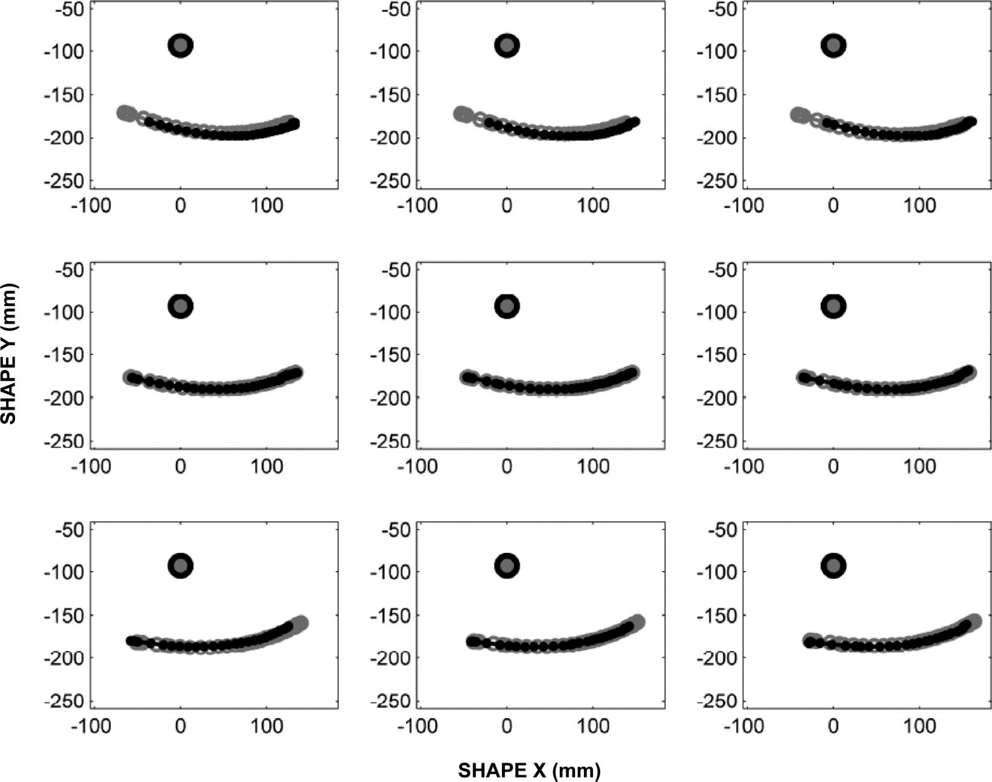
Roll-over shape results for the Highlander Prosthetic Foot. Alignment conditions match the layout shown in Figure 3. The rotated and translated neutral alignment roll-over shapes are shown with gray circles, while the actual measured roll-over shapes are shown with black dots.
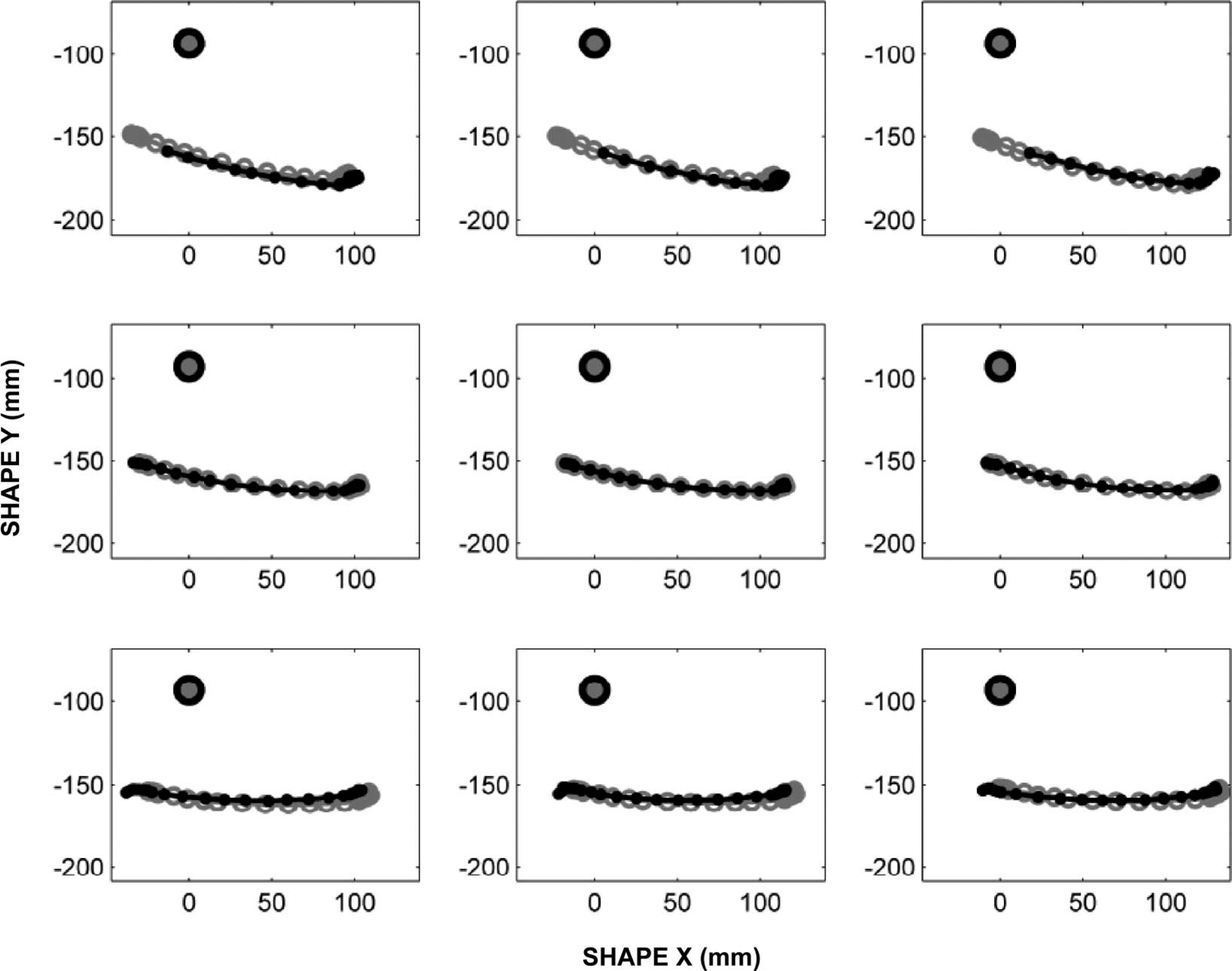
Roll-over shape results for the KSACH Prosthetic Foot. Alignment conditions match the layout shown in Figure 3. The rotated and translated neutral alignment roll-over shapes are shown with gray circles, while the actual measured roll-over shapes are shown with black dots.
Slopes and coefficients of determination (COD) for the best-fit lines to measured shifts in alignment of the circular arc models versus actual shifts made in the experiment
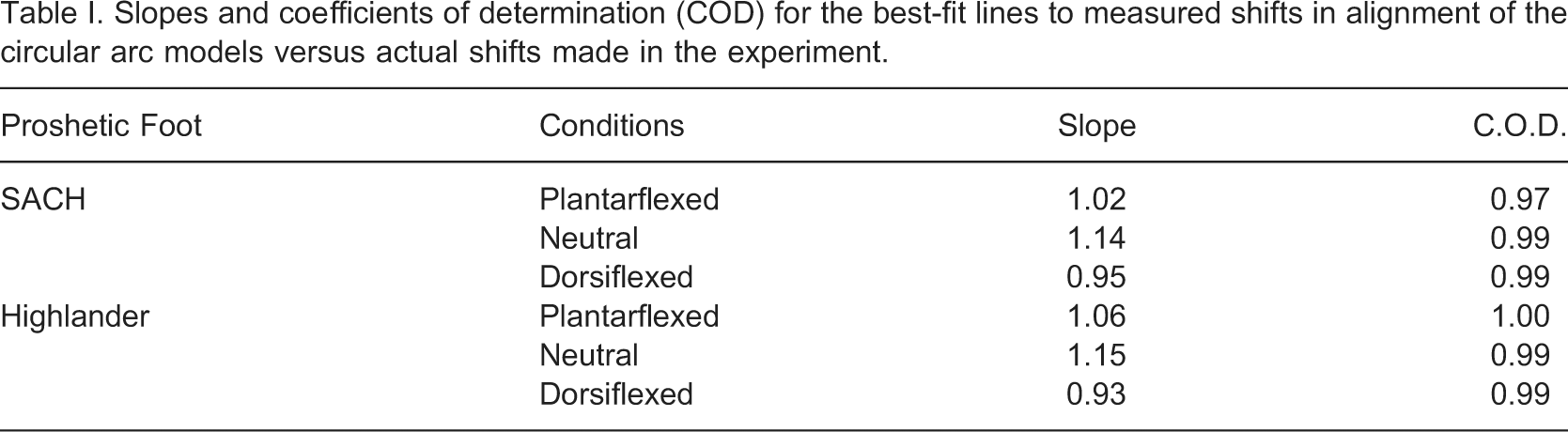
Forward shifts of the centers of the best-fit arcs for the roll-over shapes of the Highlander and K-SACH Prosthetic Feet when aligned nine different ways (see Figure 3).
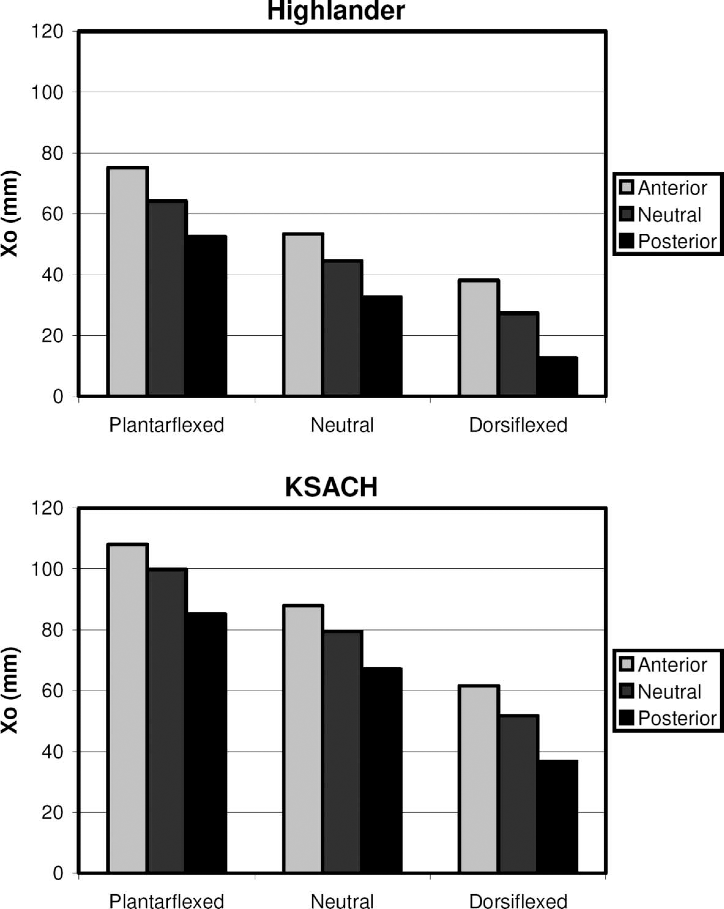
The radius of the best-fit arcs were changed only slightly with translations of the foot, but appeared to change more drastically with angular changes in the foot's alignment (Figure 7). The changes in circular arc parameters due to different alignments seemed to be greater with the K-SACH prosthetic foot when compared with the Highlander prosthetic foot. Also, the best-fit radii of the roll-over shapes for both feet seemed to decrease with plantarflexion and increase with dorsiflexion. Arc lengths of the best-fit circular arcs were also changed with angular changes in alignment, but were not changed appreciably by translations of the prosthetic feet (Figure 8).
Radii of the best-fit arcs for the roll-over shapes of the Highlander and K-SACH Prosthetic Feet when aligned nine different ways (see Figure 3). Also, the best-fit radii to the new models for the roll-over shapes are presented.
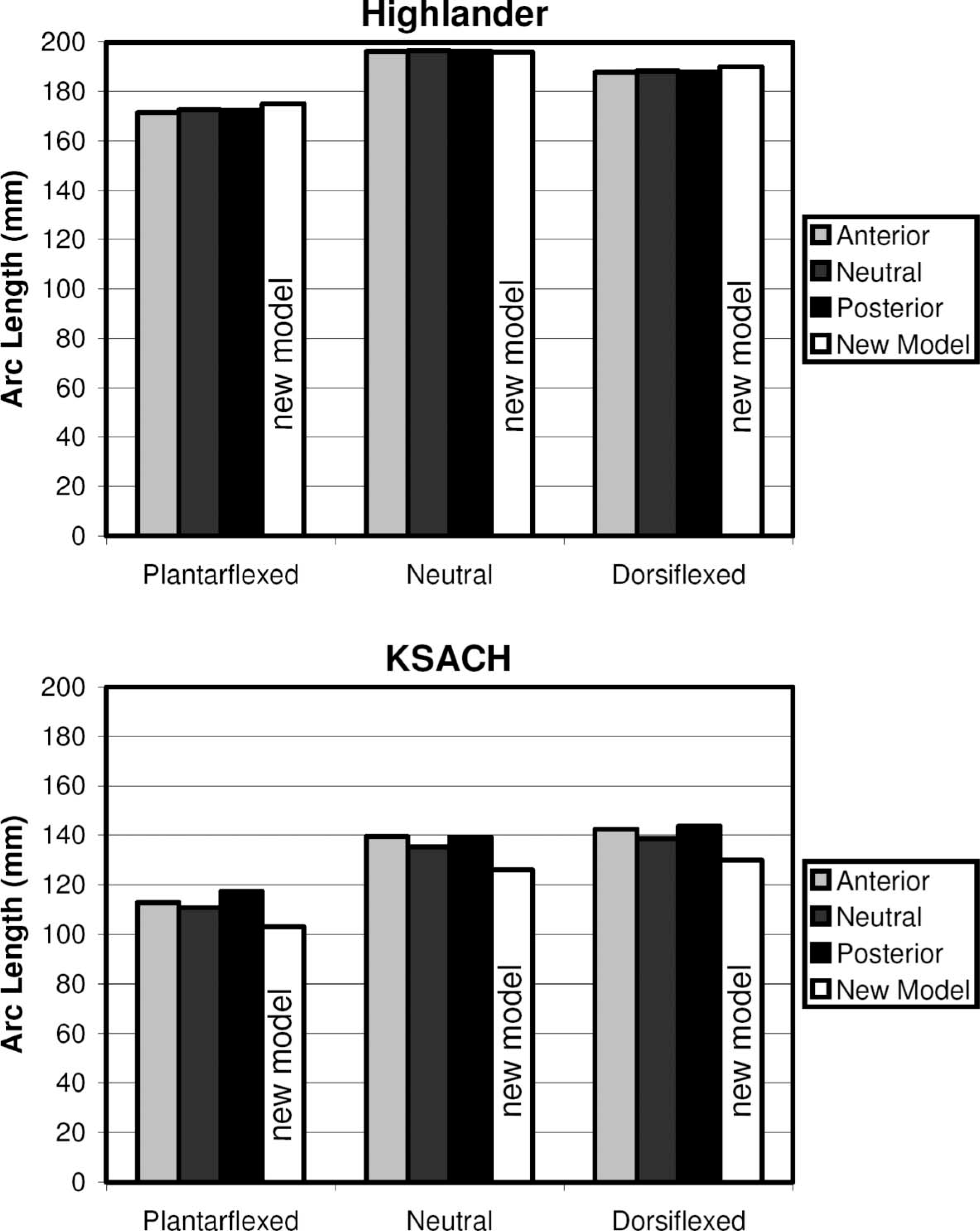
Arc lengths of the best-fit arcs for the roll-over shapes of the Highlander and K-SACH Prosthetic Feet when aligned nine different ways (see Figure 3). Also, the best-fit arc lengths to the new models for the roll-over shapes are presented.
Post-hoc model development
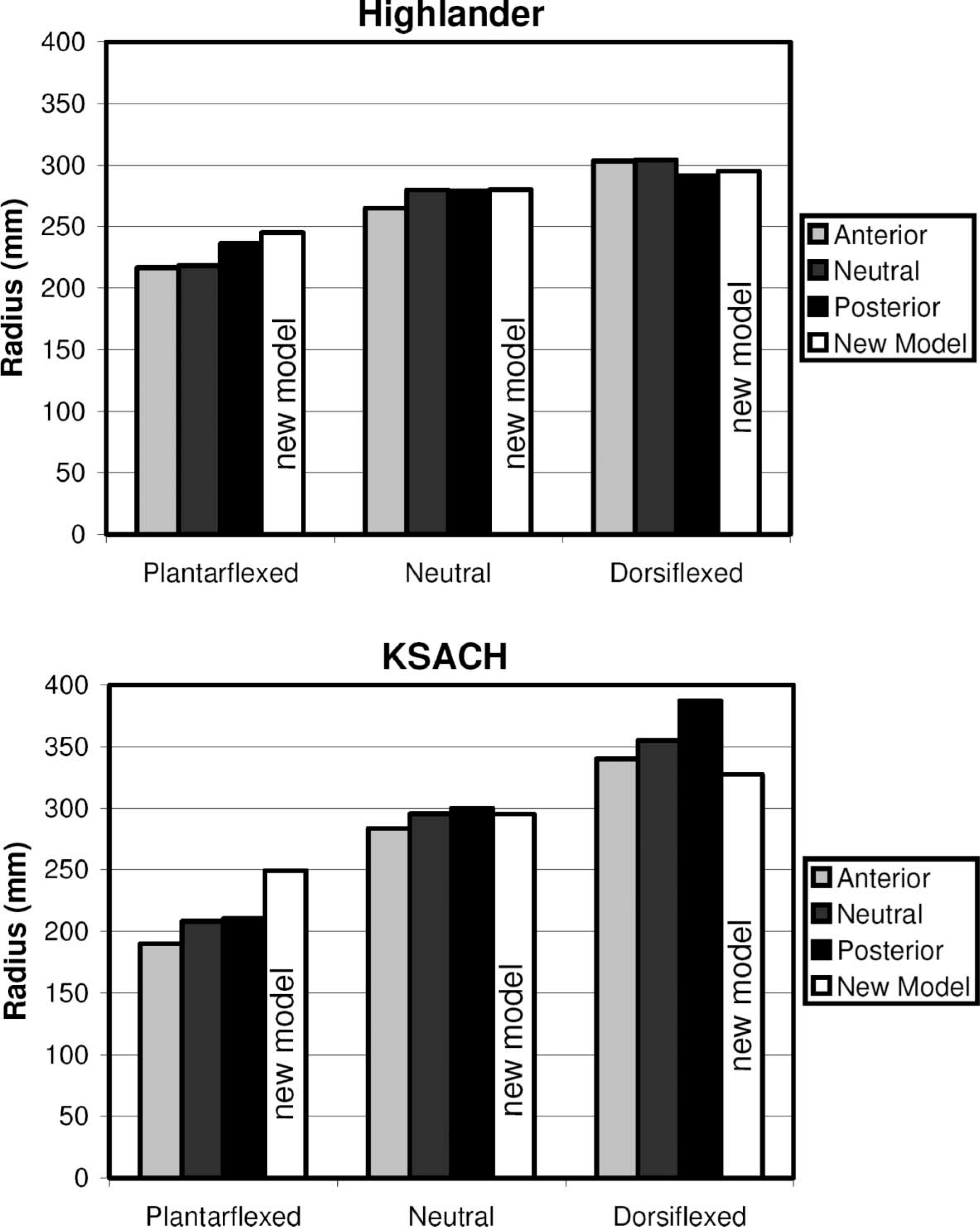
Based on the results of this study – namely that radius and arc length changed with different rotational alignments – a new model was developed. From qualitative analysis of the curves in Figures 4 and 5, we hypothesized that dorsiflexion and plantarflexion of the foot would have a similar effect as changing the range of angles through which they are loaded during walking. For example, if the prosthetic socket is assumed to go through absolute angles of −15 to 20° during walking regardless of the foot's alignment, the foot could be assumed to go through absolute angles of −20 to 15° if it were dorsiflexed 5°, and −10 to 25° if it were plantarflexed by 5°. To account for this factor, the radius and arc lengths of the best-fit arcs of the prosthetic foot roll-over shapes were determined when loading between −20 to 15° (mimicking a dorsiflexed prosthetic foot), −15 to 20° (mimicking a neutrally aligned prosthetic foot), and −10 to 25° (mimicking a plantarflexed prosthetic foot). Figure 9 shows roll-over shapes for the two neutrally aligned prosthetic feet when tested over the different ranges of loading angles. Figures 7 and 8 show the roll-over shape radii and arc lengths of the new revised model, which uses the dorsiflexion angle as a factor. The measured roll-over shape radii and arc lengths for the new models more closely approximate the measured radii and arc lengths of the roll-over shapes resulting from the nine alignment settings shown in Figure 3, although some differences are still apparent.
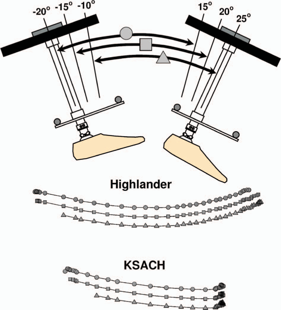
Roll-over shapes of neutrally-aligned prosthetic feet taken over different ranges of loading angles. Dorsiflexed (5°), neutral, and plantarflexed (5°) feet can be thought to experience similar loading as neutrally-aligned feet that roll through the ranges depicted by circles, squares, and triangles respectively. The roll-over shapes for the Highlander and K-SACH are aligned in the horizontal dimension, but have been offset in the vertical direction for display purposes. This exercise examines the effects of loading range on the radius and arc length. In an alignment model, these new roll-over shape models would also need to be rotated and translated according to the alignment chosen.
Discussion
This study investigated the hypothesis that prosthetic foot roll-over shapes are translated and rotated in prosthesis (socket) coordinates with corresponding alignment changes. This hypothesis was supported by the work. This study also examined the hypothesis that changes in alignment do not significantly affect the radius or arc length of the prosthetic foot's roll-over shape. This hypothesis was not supported by the work.
Results from this study showed that changes in radius and arc length due to anterior-posterior translations of prosthetic feet are present but possibly small enough to ignore when modeling alignment using roll-over shapes. However, data showed that the geometry of the roll-over shape (i.e., its radius of curvature and arc length) is altered when angular changes in prosthetic alignment are made. The changes in geometry were larger in the K-SACH foot compared to the Highlander foot. The geometries of the roll-over shapes of these feet help to explain the different magnitudes of changes. In particular, the Highlander has a roll-over shape that is more circular in nature than the K-SACH. The K-SACH foot has a roll-over shape that is fairly flat until the forefoot end of the keel has been reached. At the end of the keel, the roll-over shape ‘rolls up’, making the overall roll-over shape of the K-SACH foot look like the shape of a ski. When a prosthetic foot is dorsiflexed, its heel is loaded over a larger range of angles than would occur in a neutral alignment. This change yields more center of pressure points in the heel region (where the local radius of curvature is high) and fewer in the forefoot region (where the local radius of curvature is low). The effect of this change is a best-fit radius of the entire roll-over shape that is larger when the foot is dorsiflexed. Conversely, when the foot is plantarflexed, the opposite effect occurs, making an overall best-fit radius of the roll-over shape that is smaller than is seen in a neutral alignment. Theoretically, a roll-over shape that is perfectly circular along its length would not have changes in the best-fit rocker shape when alignment changes are made.
After recognizing the differences in loading angles that occur when changing the angular alignment of the feet, a revised approach was proposed in which prosthetic feet were tested over a range of angles larger than that used in normal walking (e.g., −20 to 25° as shown in Figure 9). In models that utilize roll-over shape to examine alignment, the center of pressure points could be chosen from this larger range such that they represent the realistic loading range for the specific angular alignment being studied. For example, when modeling feet that are dorsiflexed, the range of angles would be biased toward the heel (e.g., −20 to 15°). When modeling feet in plantarflexed positions, the range would be biased toward the forefoot loading angles (e.g., −10 to 25°). When comparing shapes found using this method with those found in direct measurement in the different alignments, the radii and arc lengths were closer, but not identical. Of particular interest is the new model's failure to fully predict the roll-over shape radius of the K-SACH Prosthetic Foot in the plantarflexed position. The changes in angles were estimated using turns of allen screws and could have been slightly more than 5° in this particular condition. If so, the measured shape may have more data points in the small radius section of the roll-over shape and fewer in the flatter portion. Small changes in these points and the high sensitivity of the circular fitting routine may explain the discrepancy between the model and the data. Hansen (2002) showed that changing one data point on an arc can drastically change the best-fit radius.
For purposes of simplicity, it may still be advisable to use the assumption that alignment alters the position and orientation of the roll-over shape in prosthesis (socket) coordinates without affecting its radius or arc length. The changes that occur in these parameters may not be clinically significant, although further work is needed to explore this issue. Additionally, the range of alignments used in this study is quite large in comparison to subtle changes that may occur in a clinical situation. Nonetheless, models that are particularly sensitive to radius or arc length parameters may require the revised approach explained in the paper and shown in Figure 9. Alternatively, future functional testing machines may allow for a simple cataloging of roll-over shapes for a wide number of alignments.
One limitation of the work presented is that only two kinds of prosthetic feet were tested and only one sample from each of these kinds was tested. The prosthetic feet used in the study were on opposite ends of the spectrum in terms of roll-over shape. Despite this large disparity in roll-over shapes, the testing yielded information that suggested a slightly revised method of modeling prosthetic foot roll-over shapes for purposes of studying alignment. This new method appears to explain changes in radius and arc length of the roll-over shapes of both feet that occurred when the alignment was altered. Also, the new method requires only a slight modification to the mechanical testing of prosthetic feet – an expansion in the range of loading angles – and does not require additional mechanical testing of the feet in a variety of alignments.
A second limitation of this work is that the prosthetic feet were tested using a quasi-static roll-over method as opposed to being tested on prosthesis users during walking. Earlier work by Hansen et al. (2000), however, suggests that the roll-over shapes found using the quasi-static roll-over method are very similar to those found under walking loads. It is important to note that those tests were accomplished with feet in the same alignment (in both tests). The results of this study suggest that the quasi-static roll-over shape should be measured in an alignment reflective of that in which it is used on the prosthesis if possible. Furthermore, it is possible that prosthesis users walking with misaligned feet may compensate and alter their gait in order to achieve a more desirable roll-over shape.
Much of our work on prosthetic foot mechanics and the roll-over shape have shown that design and structural properties of the foot are primary determinants of the roll-over shape's radius and arc length. For example, a simple removal of a wedge in a Shape&Roll Prosthetic Foot causes a dramatic reduction in the roll-over shape's arc length and subsequently affects the loading on the sound limb (Hansen et al. 2006). The changes seen in the roll-over shapes in this study are small in comparison to those seen when structural changes are made to a prosthetic foot. However, if models are particularly sensitive to radius of curvature, it is possible that the effects of alignment should be considered.
Future modeling of prosthesis alignment will likely assist in our understanding of the alignment process. The large number of prosthetic feet that are commercially available and the large number of possible alignments for each foot suggest that modeling will be necessary to gain a comprehensive understanding of the best alignments for all components. This understanding could greatly enhance the quality of prosthesis fitting worldwide and may lead to a priori alignment schemes. Knowing alignment beforehand would allow prosthetists to build it directly into the prosthesis, eliminating the need for expensive and heavy alignment hardware. This knowledge could also be of paramount importance in limb fitting facilities in developing countries, where skilled prosthetists are greatly outnumbered by persons needing their services.
Footnotes
Acknowledgements
The author thanks Dr. Sujatha Srinivasan for her questions about roll-over shapes and alignment. Her questions triggered this work. The author also thanks Ms. Rebecca Stine, Ms. Sara Koehler, and Mr. Brian Ruhe for their assistance with this project, and Drs. Dudley Childress, Steven Gard, Michael Dillon, and Stefania Fatone for proofreading the manuscript. The author would like to acknowledge the use of the VA Chicago Motion Analysis Research Laboratory of the Jesse Brown VA Medical Center, Chicago, Illinois. This work was funded by the National Institute on Disability and Rehabilitation Research (NIDRR) of the U.S. Department of Education under grant No. H133E030030. The opinions contained in this publication are those of the grantee and do not necessarily reflect those of the Department of Education.