
Abstract
Background and aim:
DEKA Integrated Solutions Corp. (DEKA) was charged by the Defense Advanced Research Project Agency to design a prosthetic arm system that would be a dramatic improvement compared with the existing state of the art. The purpose of this article is to describe the two DEKA Arm prototypes (Gen 2 and Gen 3) used in the Veterans Affairs Study to optimize the DEKA Arm.
Technique:
This article reports on the features and functionality of the Gen 2 and Gen 3 prototypes discussing weight, cosmesis, grips, powered movements Endpoint, prosthetic controls, prosthetist interface, power sources, user notifications, troubleshooting, and specialized socket features; pointing out changes made during the optimization efforts.
Discussion:
The DEKA Arm is available in three configurations: radial configuration, humeral configuration, and shoulder configuration. All configurations have six preprogrammed grip patterns and four wrist movements. The humeral configuration has four powered elbow movements. The shoulder configuration uses Endpoint Control to perform simultaneous multi-joint movements. Three versions of foot controls were used as inputs. The Gen 3 incorporated major design changes, including a compound wrist that combined radial deviation with wrist flexion and ulnar deviation with wrist extension, an internal battery for the humeral configuration and shoulder configuration, and embedded wrist display.
Clinical relevance
The DEKA Arm is an advanced upper limb prosthesis, not yet available for commercial use. It has functionality that surpasses currently available technology. This manuscript describes the features and functionality of two prototypes of the DEKA Arm, the Gen 2 and the Gen 3.
Background and aim
In 2005, the Defense Advanced Research Project Agency (DARPA) 1 announced a new research project, the “Revolutionizing Prosthetics” program, the goal of which was to drastically improve the quality of life for upper limb amputees. This initiative was spurred by the increased rates of services members with upper limb loss due to combat injuries from Iraq and Afghanistan. Development of the DEKA prosthetic arm system was funded as one of the initiatives of the Revolutionizing Prosthetics program. DEKA Integrated Solutions Corp. (DEKA) was charged with developing an upper limb prosthesis which would represent a dramatic improvement compared with the existing state of the art. Goals for the arm system included more powered degrees of freedom (DOF); including wrist, elbow, and shoulder joints, innovative new control schemes, increased lift and grasp capability with multiple grasp options, and modularity to address amputations at different levels.
After 2 years of research, DEKA had built and performed initial testing of Generation 1 (Gen 1) and Generation 2 (Gen 2) arms which had been built and tested with a small group of clinicians and amputees. DARPA then initiated a second phase of the contract with DEKA to develop the next Generation prototype (Gen 3) and also provided funds to DEKA to support the Department of Veterans Affairs (VA) in conducting clinical usability studies of the Gen 2 to inform the design of the Gen 3, and provide feedback on the Gen 3’s refinement. In 2008, the VA and DARPA entered into a Memorandum of Agreement to collaborate on a joint study to optimize the DEKA Arm so that it would best meet the needs of wounded service members, and the VA Rehabilitation Research and Development Service funded the multisite VA Study to optimize the DEKA Arm (Optimization Study). The Gen 2 DEKA Arm was designed as an experimental platform, and as such, it included many test features that had not yet been finalized or miniaturized. Before moving to the Gen 3 design, DEKA obtained feedback from the VA study and from studies of their own subjects and made numerous smaller iterative changes to Gen 2 features and software. Most of the major hardware and design changes, however, were introduced in the Gen 3. 2 The purpose of this article is to fully describe the Gen 2 and Gen 3 prototypes and provide a synopsis of DEKA’s optimization efforts.
Technique
The DEKA Arm was available in three configurations, or levels: the radial configuration (RC), which was appropriate for transradial amputees; the humeral configuration (HC), which was appropriate for transhumeral amputees; and the shoulder configuration (SC), which was appropriate for transhumeral amputees with very short residua, as well as persons with amputations at the shoulder disarticulation and scapulothoracic (forequarter) level. The two device prototypes with SC are shown in Figure 1. In the following, we describe commonalities of the Gen 2 and Gen 3 prototypes, explain key changes made within the Gen 2 during the Optimization Study, and highlight major differences between the Gen 2 and Gen 3 systems.
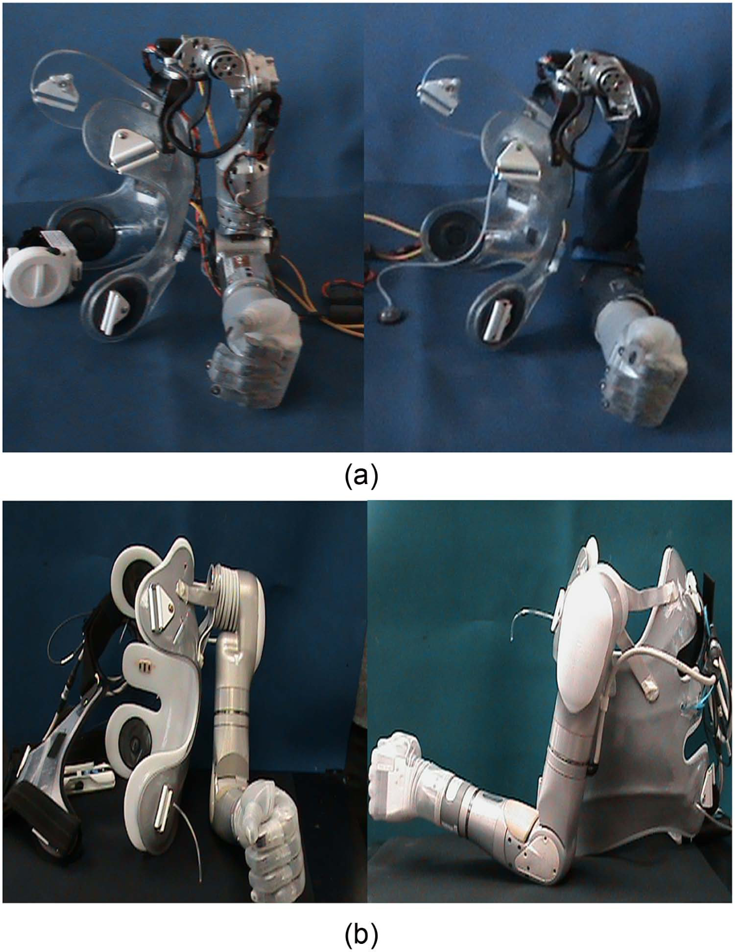
Appearance of DEKA Arm Gen 2 and Gen 3 Prototypes: (a) Gen 2 SC Arm on socket/harness without sleeve (left) and with sleeve (right); (b) Gen 3 SC Arm on socket/harness: anterior view (left) and lateral view (right).
Weight and cosmesis
The weight of the Gen 2 SC Arm system was approximately 8 lbs, without accompanying cables, external battery, or other accessories. The HC weighed 5.6 lbs, and the RC weighed 2.5 lbs. The weight of the SC Gen 3 was 9.8 lbs. The HC level was 6.8 lbs, and the RC level was 2.8 lbs.
The appearance of the Gen 3 was quite different from the Gen 2. The overall size of the Gen 3 was smaller, the hand shape was less square and blocky, and the elbow and shoulder were more contoured. The Gen 3 SC shoulder abductor motor was quieter than the Gen 2 motor. The Gen 3 shoulder interface was mounted to the socket vertically, in the sagittal plane, as opposed to the Gen 2 version that was mounted horizontally, in the transverse plane.
The Gen 2 had a metal exterior with exposed mechanics and a fabric sleeve to protect the arm from moisture and dust. The Gen 3 metallic, external structure did not have exposed mechanics or require a fabric sleeve. Both Gen 2 and Gen 3 had removable fingernails; however, some of the fingernails of the Gen 3 hand were made longer. Both prototypes were dust- and water-resistant, although the Gen 3 had significantly greater dust and water resistance. The hand and glove could be cleaned with a wet washcloth, the entire Arm was resistant to light rain, and the fingers (up to the base) could be immersed in water.
Grips
Both prototypes supported the use of up to six different preprogrammed grip patterns which provided options for both precision and power grasps, as shown in Figure 2. In power grip, the distal thumb closed against the distal lateral aspect of the index finger, while the other digits remained in composite flexion, forming a loose fist and enabling an object to be held against the palm. Power grip was used to grasp large objects such as bottles, books, and handles. In fine pinch open (open tip pinch), the distal pad of the thumb opposed the index finger and the remaining fingers stayed extended and out of the way. Open pinch was used to manipulate and pick up small objects. Fine pinch closed (closed tip pinch) was similar to open tip pinch except that the middle, ring, and fifth digits closed in composite flexion instead of remaining extended. The chuck grip (three-jaw chuck pinch) was similar to a tripod pinch where the thumb opposed the distal index and middle finger pads while the ring and small fingers flexed with the hand close operation. Chuck grip was used to grasp medium and small size round objects such as bottles, cups, or doorknobs. In lateral pinch, the distal ulnar aspect of the thumb closed against the radial aspect of the flexed index finger, while the middle, ring, and small fingers also flexed. Lateral pinch was used to grasp flat items such as keys, files, or papers, and writing and eating utensils. In tool grip, the index finger flexed to touch the proximal phalanx of the thumb, while the middle finger, ring finger, and small fingers closed in composite flexion. If the user kept the index finger in the extended position, this grasp could be used to perform activities requiring a pointer finger, such as typing or playing the piano. If the user actively used the grasp, the index finger could be flexed to activate a tool such as an electric drill, or utilize a spray bottle, while the remaining fingers remained flexed to stabilize the object.
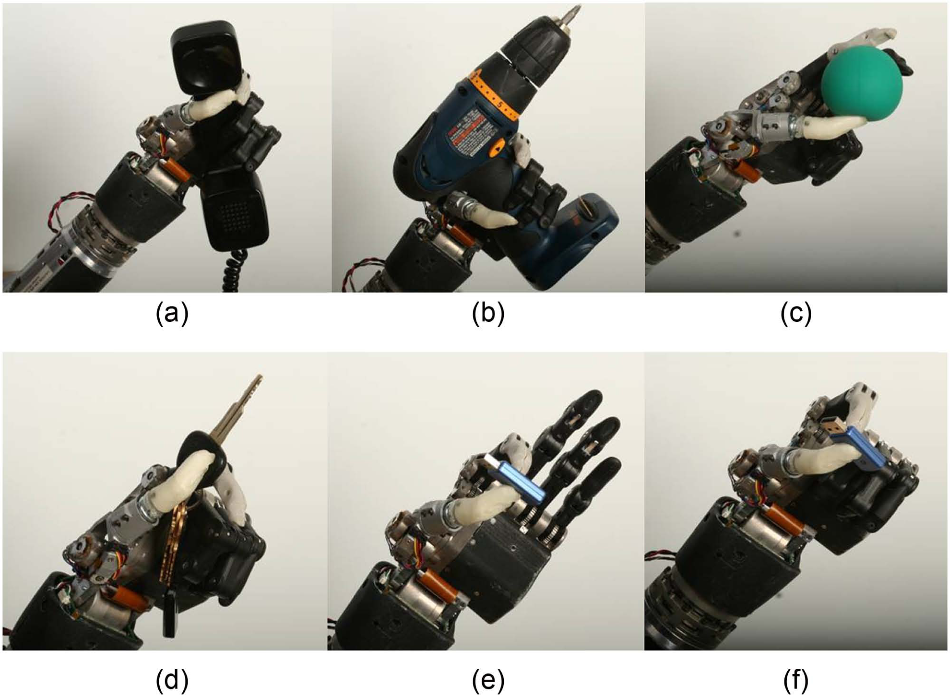
Six grips of the DEKA Arm (Gen 2 Hand): (a) power, (b) tool, (c) chuck, (d) lateral pinch, (e) fine pinch open, and (f) fine pinch closed.
Three grips—tool, lateral pinch, and fine pinch closed—were modified in the Gen 3 by adding a new feature called a detent. The detent allowed users to separate the positioning/stabilizing and grasping aspects of grip from the precision portion and minimized unintentional finger movements while grasping, releasing, or manipulating a given object. The user activated the hand close signal to close the hand to the first detent position, ceased (or zeroed) the command, and then repeated the command to close the grip the rest of the way (Figure 3). The added functionality was most evident in the tool grip, where the first command signal could be used to close the hand around the object, and then the second command was used to close the index finger and activate the tool. The detent also worked for hand opening; thus, the user was able to open the grip part of the way (to the detent), and therefore could open and close the index finger in isolation, without releasing grip on an object already placed in the hand. Users activated two consecutive signals in order to fully open or fully close the hand when using a grip with a detent.
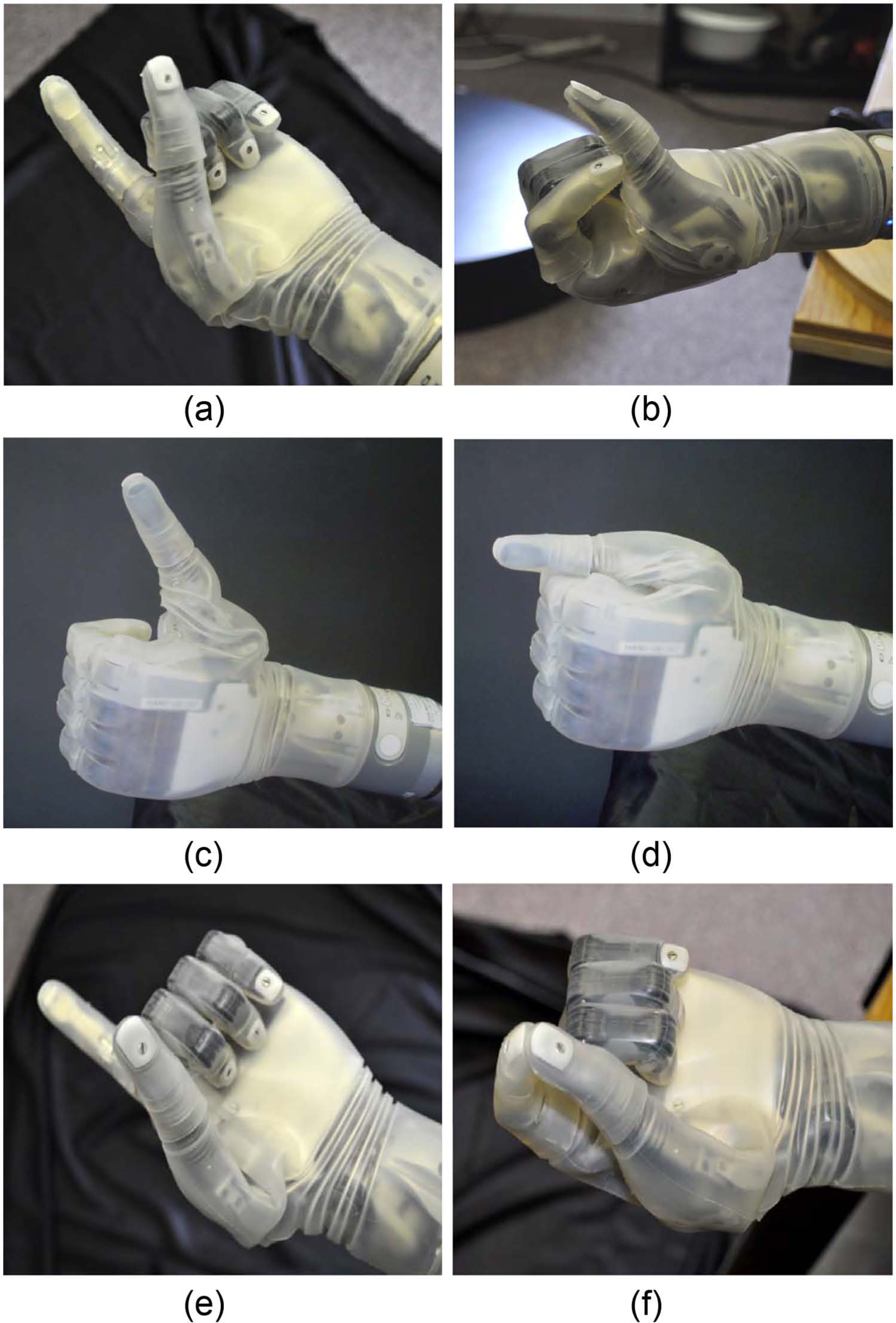
Grips with detents: (a) tool grip at first detent, (b) tool grip closed fully, (c) lateral grip at first detent, (d) lateral grip closed fully, (e) closed pinch grip at first detent, and (f) closed pinch grip closed fully.
Users selected the grip that they wished to use through one of two methods: direct selection (four grips could be chosen this way) or by toggling (six grips could be used). Toggle grip selection allowed users to rotate through the grips in a specified order and select the grasp by utilizing a control input signal. Initially users were only able to toggle in one direction through the set of grips; however, the ability to toggle in both directions was added during Gen 2 testing. In Gen 3, it became possible to customize what grips were available, eliminating the ones a user did not find useful.
In Gen 2, whenever the Arm was powered down and then repowered, the hand automatically reset itself to the first grip in the sequence. However, changes were made in Gen 3 so that when the Arm powered on, the hand automatically returned to the grip that had been used just prior to powering down. The force of several of the grip patterns was increased, and the finger alignment was slightly altered in Gen 3 as well.
Powered movement
The SC DEKA Arm had 10 powered DOF and additional passive DOF.2,3 Powered DOF included shoulder abduction/adduction; shoulder flexion/extension; humeral internal/external rotation; elbow flexion/extension; forearm pronation/supination; wrist flexion/extension; index finger flexion/extension; middle, ring, and fifth finger flexion/extension; thumb flexion/extension; and thumb abduction/adduction. Additional passive DOF included movements of the finger phalanges of digits 4 and 5, which were slaved to the middle finger. A major change in the Gen 3 was the inclusion of a compound wrist movement that incorporated some degree of radial and ulnar deviation. In the Gen 3 wrist, radial deviation was combined with wrist flexion and ulnar deviation was combined with wrist extension.
All levels of the DEKA Arm used control inputs for the hand and wrist including grip selection (to choose between the grips), wrist flexion and extension, wrist pronation and supination, and opening and closing of the hand. The HC DEKA Arm used control inputs for all movements included in the RC Arm as well as for the movements of elbow flexion and extension and humeral internal and external rotation. The SC DEKA Arm used inputs for all movements available in the HC Arm as well as for combined movements of the shoulder and elbow in patterns called Endpoint Control.
At the HC and SC levels, the control scheme had dual modes enabling the user to switch between a “hand mode” of operation (to control movements of the hand and wrist) and an “arm mode” of operation (to control movements of the powered elbow, shoulder, or combined movements, that is, Endpoint Control). In Gen 3, changes were made to enable availability of up to three movements of the hand and/or wrist in arm mode, if sufficient control inputs were available.
Endpoint Control
The SC DEKA Arm employed Endpoint Control to enable simultaneous, coordinated movement of the prosthesis to bring the terminal device (the endpoint) to a desired position in space. In Endpoint Control, the user indicated a single command, for example, “move hand up,” and the Endpoint Control software automatically engaged the necessary joints to move the prosthetic hand up in space. During the Optimization Study, there were three different versions of Endpoint Control, each with some differences of movement trajectories and features.
The first Endpoint Control version used a cylindrical coordinate system with 6 DOF: up/down, forward/backward, and humeral internal/external rotation on a cylindrical surface oriented on the shoulder mounting plane. In addition, there was a separate control, not included in the Endpoint system, which abducted and adducted the shoulder. Abduction and adduction of the shoulder affected the axis of rotation of the shoulder motors and therefore influenced the plane and direction of the Endpoint commands, as all movements were in relationship to the shoulder mounting.
The movement patterns of the second version of Endpoint Control used a Cartesian coordinate system with 6 DOF: up/down, forward/backward, and left/right. Voluntary elbow positioning (VEP) was used to control the shoulder abductor/adductor motor to provide additional control over elbow position for a given hand position. Finally, the third version of Endpoint Control, a refinement of the second version which changed the trajectory of the elbow movement, also had six movement patterns: up/down, forward/back, left/right, as well as VEP. In the second and third versions of Endpoint Control, humeral internal and external rotation was included within the trajectories of the other movements as needed to achieve the Endpoint movement.
In all versions of Endpoint Control, the design of the shoulder prevented movement in the upper spatial quadrant (beyond 90° of shoulder abduction). Thus, there was a “functional window” of operation with built-in software stops to prevent damage to the hardware. If users attempted to move the Arm beyond the limits of the functional window, it would stop moving in the commanded direction. The Gen 3 shoulder abductor joint was redesigned to be more consistent in speed of movement and less prone to stalling under load. All versions of Endpoint Control had slowdown zones near the area of the head that reduced the speed of motions toward the head and face. In the Gen 2 Arm, an abrupt change in the speed of motion toward the head created a slight jerkiness to the Arm movement during this transition. This transition was updated to be much smoother in the Gen 3 design.
Controls
Users controlled prosthetic movements with a combination of foot controls, myoelectrodes (electromyography (EMG)), pneumatic bladders, or other commonly available prosthetic input devices. Users worked with the prosthetist to identify the appropriate combination of these potential control elements, and did not necessarily use all, or any specific, control elements other than some type of foot control.
The three iterations of foot controls are shown in Figure 4. These included force sensitive resistors (FSRs), inertial measurement units (IMU) during Gen 2 (IMU-1), and a refined, miniaturized version of the IMU in Gen 3 (IMU-2). Gen 2 FSRs included sensors soldered onto foot pads worn inside the shoes. The user commanded motion of the prosthesis by applying pressure to the sensors on different areas of the foot.
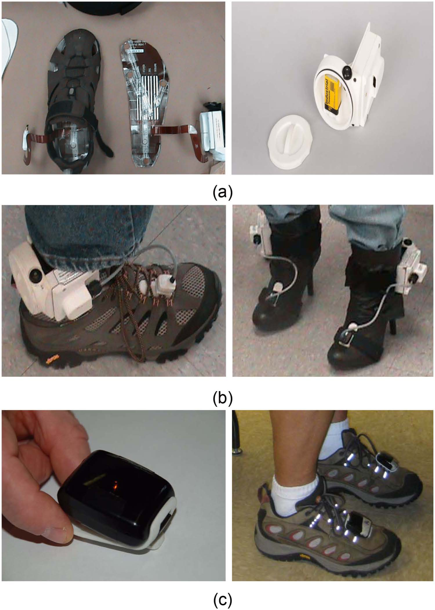
Three iterations of foot controls: FSRs, IMU-1, and IMU-2: (a) FSR footpad wired to ACI (left) and ACI unit and battery (right); (b) IMU-1 and ACI battery unit worn on shoes (left) and boots (right); (c) IMU-2 on clip (left) and worn on laces (right).
IMUs, mounted on a clip that attached to the top of the shoe, utilized gyroscopes and micro electromechanical systems (MEMS) accelerometers to sense small movements of the foot/ankle in space in relation to a flexibly programmed “zero” position. The user commanded motion of the prosthesis by tilting his or her foot (and the IMU) in various directions. The Gen 2 IMU-1, like the FSR, was attached by wire to an arm control input module (ACI) battery unit worn around the ankles. The miniaturized Gen 3 IMU-2 was wireless and contained its own battery. New features of the IMU-2 included the ability to automatically detect walking motion and put the arm into standby (Walk Detect), as well as “over angle limit detect” to minimize the possibility of activation of unintended prosthetic movements if a user tripped or stumbled.
These user inputs were received and digitized by one or more ACIs which then transmitted these signals to a master control module (MCM). The MCM generated and transmitted the arm control commands to the respective electrical module that controlled the mechanical prosthetic movements. All control inputs were initially configured by a wireless graphical user interface (called the prosthetist interface (PI)) that ran on a personal computer and was available to the clinician, but not designed for the amputee user. The MCM of the Gen 2 was mounted externally as was an external battery supply (Figure 5). The Gen 3 replaced the MCM unit with a master arm control (MAC) unit which was internalized in the wrist of the device. User perspectives on utilizing the foot controls are fully described in a separate article. 4
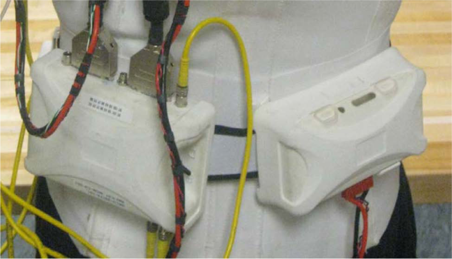
Gen 2 MCM (left) and battery pack (right) worn on the back.
The wireless communication connection between the computer and the MCM, as well as between the foot controls and the Arm, was upgraded during Gen 2 and replaced at the start of Gen 3 with an updated wireless communication connection to increase signal reliability and decrease interruptions in device functioning due to communication losses.
Prosthetist interface
Ongoing changes were made in the intuitiveness, accuracy, ease of use, number of steps, and screens required for the prosthetist to initially set up and adjust the device controls during Gen 2 and Gen 3 via the PI. By the start of Gen 3, the IMU setup process had been simplified greatly. There was less wait time required when updating configurations and the frequency of need to power-cycle the Arm to install a new configuration was reduced.
Troubleshooting faults and stoppages
Troubleshooting arm malfunctions required a series of steps, the first of which was powering down the Arm and re-initializing it. If re-initializing the Arm did not work, other fixes might include checking EMG and wiring connections, manual adjustment of a joint that had been moved beyond normal range, and replacing or recharging batteries. Some, but not all, faults and stoppages were indicated by the visual notification system Luke User Interface (LUI) and wrist display and may have had an accompanying error source indicated on the PI event log (a record of faults and operations like startup/shutdown.)
The process for troubleshooting was similar in the Gen 2 and Gen 3 prototypes; however, the time involved and number of steps required were greatly decreased for the Gen 3 Arm system due to the improvements in initializing and wireless communication. The length of time required to power-cycle was greatly reduced for the Gen 3 as well, so that the Arm was repowered with minimal delay and went into standby, immediately ready for activation of controls.
The Gen 3 Arm had a new feature which allowed a manual override in cases of malfunction or freezing. A button on the dorsum of the Gen 3 hand was added that could be pressed to open the hand if it was closed and not responding to commands. However, battery power needed to be provided to the Arm for this to work. The same button could be pressed for a longer time to disengage the brakes, allowing the joints of the Arm system to be manually adjusted.
Power sources
The DEKA Arm was battery powered using a rechargeable lithium-ion battery typically worn in a holster on a belt around the waist or on the back. The ACI for the FSRs and IMU-1 used a standard 9-V battery that needed replacement when discharged. The size of the external rechargeable battery was decreased between Gen 2 and Gen 3, and the holster in which it was mounted was redesigned for ease of insertion and removal of the battery. A power-save mode was developed during Gen 2 that could engage joint brakes to stop motors from running during inactivity, resulting in longer run-times for batteries in HC and SC Arms. The Gen 3 also included this power-save mode.
In Gen 3, an alternating current (AC) adaptor and charging dock replaced the Gen 2 cable system that charged one battery at a time. The Gen 3 charging dock could charge two external batteries simultaneously and was easier to operate with only one hand. The Gen 3 for HC and SC also had the potential to include an internal battery built into the Arm. The internal battery itself was introduced late in the Gen 3 phase. RC level Gen 3 Arms did not have an internal battery. When an internal lithium-ion battery was used, the Arm was turned on and off by a button located in the forearm above the wrist area.
Internal batteries were charged via an AC adaptor between an electrical outlet and a charging port on the forearm of the Arm and were expected to offer run time of at least 1 h between charges, depending on intensity of use. In all cases, the internal battery could be augmented by an external battery which was expected to offer run time of at least 6 h between charges, depending upon the intensity of use. The internal ACI battery for IMU-2 was a rechargeable lithium-polymer battery with average run time specifications of a full day between charges. The entire IMU-2 unit was placed on a charging pad which was updated during Gen 3 by adding light emitting diode (LED) signals that indicated when the IMUs were charging.
The Gen 2 Arm required a series of steps to initialize it before operation. Initializing involved (1) turning on the left and right ACI batteries for foot control, (2) turning on the main external battery, and (3) activating an enable switch on the MCM module. If the Arm stopped working for any reason, the user re-initialized by manually powering down the main external battery and each ACI battery, disabling the MCM control and then repeating the initialization process. Due to the number of steps and the programmed delays in repowering the system, this process took a minimum of about 30 s and often took a minute or more. The delays in the system were shortened slightly during Gen 2, but the number of steps remained the same. The initialization process for the Gen 3 Arm was simpler and faster. To initialize the Arm, the user simply gave the IMUs a shake to make sure they were not in sleep mode, then powered on the device using the internal or external battery power button. This automatically powered on the prosthesis and foot controls and placed the Arm in standby mode, ready for activation into hand or arm mode by control inputs.
User notification systems
The DEKA Arm provided several auditory notifications. In the Gen 2 Arm, a beeping sound occurred when the Arm powered on and off. Additionally, a series of beeps occurred to signal a low battery charge and a different tone occurred if there was a system fault. In addition, an audible tone and a vibratory tactor were used to provide notification when there was a change in device status, such as when changing between hand and arm mode, moving into or out of standby, changing grip and changing grip pressure. The tactor was placed on or near the subject’s skin, and in Gen 2, it was connected by cable to the MCM. In Gen 3, the tactor was connected to an ACI.
The system did not have a “default” mode, a feature that would automatically place it into a specified mode of choice (arm or hand) after a given period of inactivity. The Gen 2 system initially did not have any visual notification of mode status; thus, users had no way of knowing which mode (hand or arm) they were in without moving the arm (if they had forgotten). In addition, the early Gen 2 did not provide the user with any type of visual notification of grip selection. As a result of user and clinician feedback during Gen 2 studies, the LUI was introduced in the Gen 2 phase to fulfill this function. The LUI was a small device with a screen that could be worn like a large wristwatch or at the waist (Figure 6). It displayed information about the grip selected, the mode of the Arm (arm vs hand mode), power/standby status, main battery charge levels, and a code to indicate the source of a system fault or stoppage. Possible reasons for faults and stoppages were mechanical/motor malfunctions in a shoulder, elbow, or wrist; wireless communication losses between the Arm and IMUs; out of range movements detected by built-in position sensors; very low battery charge; or other sources. Prior to the LUI, users were not able to view any information about the presence of or reason for an Arm stoppage, although the clinician could view the error event logs via the PI.
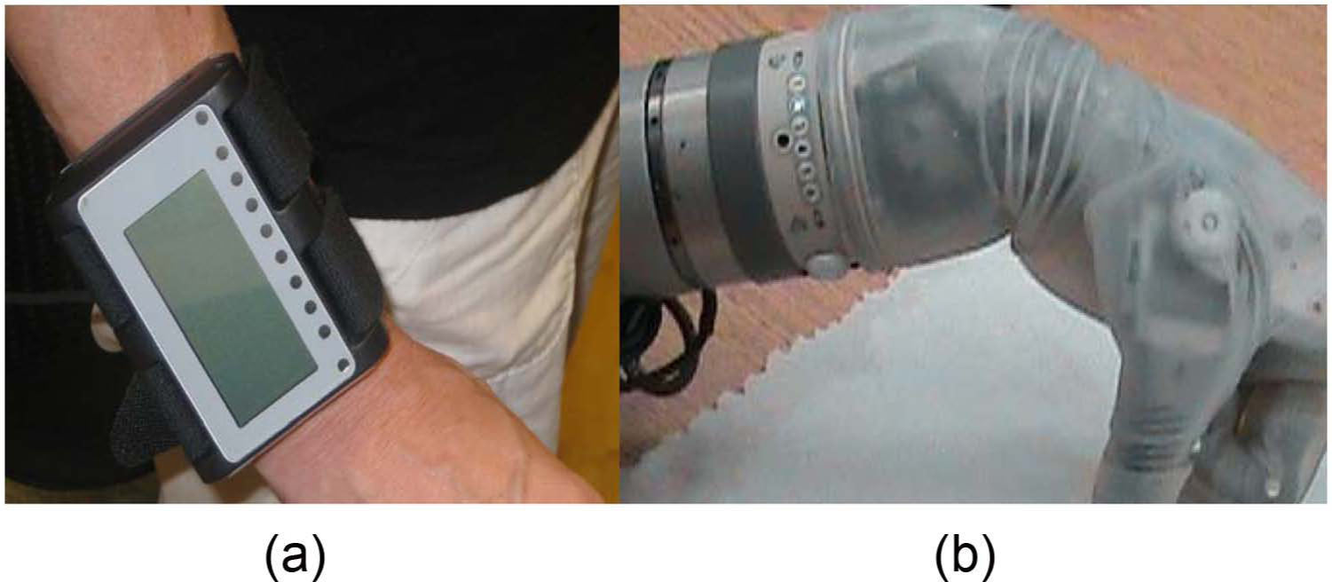
Visual notification systems of the Gen 2 and Gen 3 DEKA Arms: (a) LUI worn on wrist; (b) wrist display embedded into Gen 3.
The Gen 3 replaced the LUI with a wrist display embedded on the dorsal wrist area of the DEKA Arm. The wrist display (Figure 6) had adjustable brightness LED displays for grip, low battery, mode notification, and system faults, as well as indicators for Walk Detect and over angle limit detect. The wrist display simplified notification about error messages by using two blinking lights to indicate that an error had occurred, but did not provide information about the nature of the error or fault. Detailed error information was only available through the PI software. IMU-2s introduced a second user visual notification system via an LED light on each IMU that indicated (1) whether the IMU was in Walk Detect or normal operating mode, (2) IMU battery charge level, and (3) IMU fault status.
Socket design
DEKA developed several features to increase the stability and comfort of the prosthetic socket with the expectation that a more stable fit would increase usability for higher load activities and tolerance to the weight of the device. Specialized, inflatable, socket bladders or actuators were provided to be embedded inside transhumeral sockets using a special design aimed at increasing skeletal stabilization (Figure 7). Socket bladders came in a variety of sizes and could be inflated and deflated manually to allow easier socket donning and doffing, and adjust to changes in limb volume. Inflatable bladders could also be placed inside X-frame sockets for higher level amputees to provide additional cushioning and pressure release when using the SC Arm.
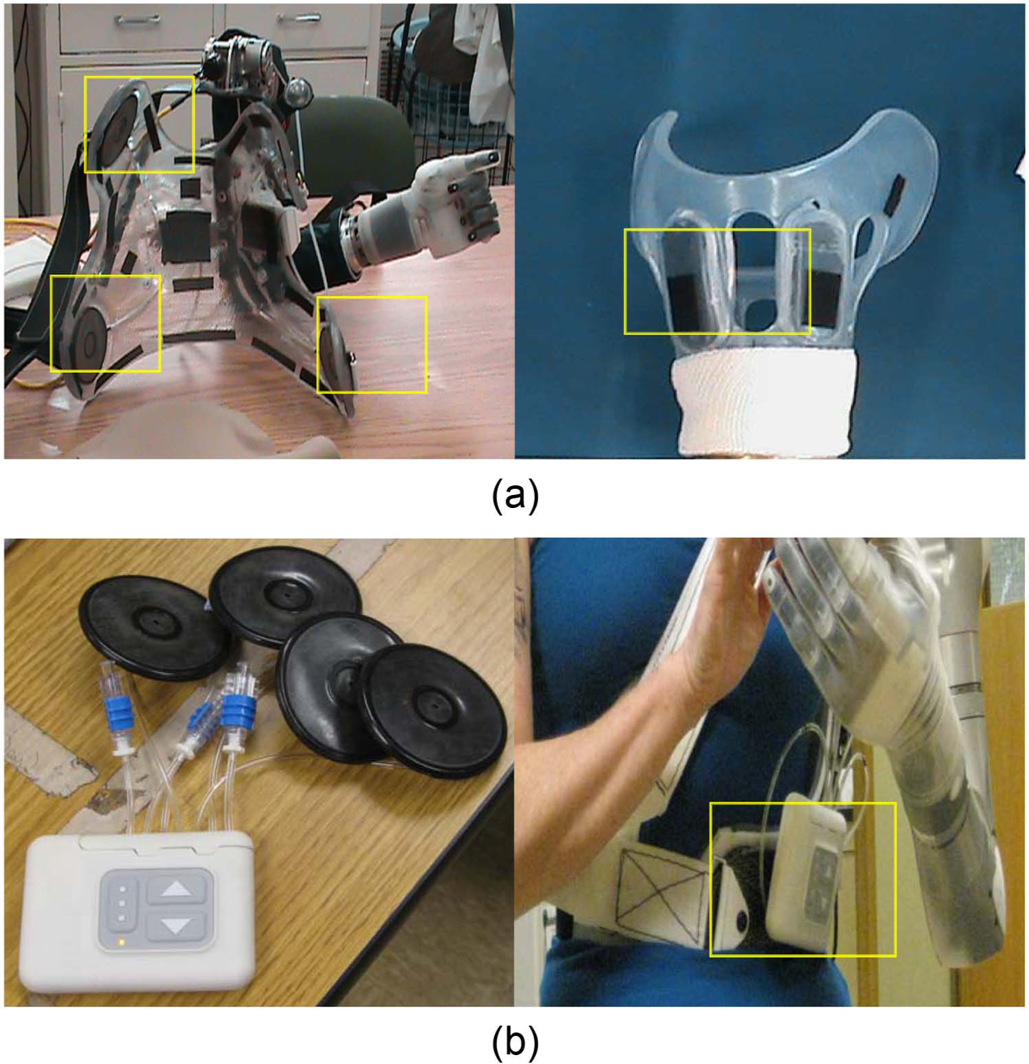
Socket bladders and DSC: (a) Gen 2 inflatable bladders imbedded SC socket (left) and HC (right) socket; (b) socket bladders attached to DSC unit (right), and DSC unit worn on belt box.
During the Gen 3 phase, DEKA introduced a dynamic socket controller (DSC) that could be used to regulate inflation of the socket bladders through independent pneumatic channels using the touch of one or more buttons (Figure 7). The DSC also included a button that would automatically vent all socket bladders to allow for easier donning or doffing. The DSC was a separate control unit with its own rechargeable battery, typically mounted on a waist belt or to the socket itself. The DSC also allowed users to set a relief mode which alternated the pressure of bladders one by one, establish an alternating “massage mode.”
Discussion
The development of the DEKA Arm system is best appreciated in the context of other seminal research and development work in upper limb prosthetics on multifunction hands, control methods, sensory feedback, wrist units, humeral rotator, and shoulder design and Endpoint Control.
Although many have described the development of multifunctional prosthetic hands and other prosthetic features, there is a paucity of articles describing devices that have been evaluated in clinical studies of persons with amputation. Only a few powered multifunction prosthetic hand designs, including the i-Limb products (i-Limb, i-Limb pulse, i-Limb Ultra, and i-Limb Ultra Revolution) 5 and the Ottobock Michelangelo Hand, 6 have reached the commercial marketplace. Historically, the design and features of devices in the commercial marketplace have not been identified or fully described in the scientific literature and descriptions are only available through technical specification documents produced by the manufacturer after commercialization.
The literature describing multifunctional powered prosthetic hands is substantial and spans more than two decades. Most powered multifunctional hands have between 1 and 6 actuators and between 8 and 16 joints.7–23 Most of these hands are underactuated, have conforming grips, can perform several grasp patterns, and are designed with 5 digits, although several designs have only 3 digits. 10 Although a complete review of the state of the art of research prosthetic terminal devices is beyond the scope of this article, a comparison of the digits, joints, number of actuators and actuation methods was provided by Dailey et al. in 2010. 13 One device, not included in Dailey et al.’s review, has 22 joints and additional actuators for control of individual digits. 24 Some of the multifunction terminal devices can perform 6 or more grasping patterns as well as additional hand postures,19,24–26 offering potential functionality that is similar to or exceeds that of the DEKA hand.
A variety of methods for controlling powered multifunction upper limb prostheses have been proposed, including targeted muscle reinnervation, 27 EMG pattern recognition,28–31 and even foot controls. The first trials of foot control systems for upper limb prosthetic devices can be traced back 60 years.32,33 Since that time, a variety of foot control methods have been described, including use of strain gauges on the big and little toe embedded in footwear,34,35 position sensors placed on the ankle, 36 and FSRs on four areas of the sole (heel, big toe, lateral left, and lateral right).37,38 To our knowledge, there have been no previous reports of using IMU on the feet as a means of upper limb prosthetic control.
A multitude of sensory feedback systems have been developed and applied in upper limb prosthetics. Most of these sensory feedback systems have been evaluated through bench testing, with nondisabled subjects, and/or with one or two amputees. The most commonly described types of sensors are tactile sensors located in the thumb and/or index and middle fingertips that provide the user with information on touch or object slip.39,40 Feedback is provided to the user through a vibrotactile or electrotactile interface. Such interfaces have been evaluated in combination with several prosthetic hand designs including, but not limited to the MANUS, 22 the Southampton Hand, 41 the CyberHand,25,42 the HIT/DLR Prosthetic Hand, 43 and others. 44 The most sophisticated sensory feedback systems were developed to sense position, tactile/pressure and force, and are intended to be connected to the user through a neural interface. 45 Some multifunction prosthetic hands, including the CyberHand, 46 the Smart Hand, 47 and the Intrinsic Hand, 24 have advanced sensory capabilities and control of individual digits and were developed as prototypes for testing and evaluating neural interfaces, control algorithms, and sensory feedback protocols.
Although some prostheses are now available with passive wrist flexion and extension, and many commercially available devices have powered pronation and supination, at this time there are only a few commercially available wrists that incorporate powered flexion and extension. Two commercial wrists have powered wrist flexion: the Centri Hand and wrist which combines wrist flexion and finger flexion, and the hand and wrist supplied by Shanghai Kesheng Prostheses Co. Ltd, 48 that has separate powered wrist flexion. We located only a single published peer-reviewed article describing the engineering design of a 2-DOF prosthetic wrist. 49 However, the Intrinsic Hand supported by DARPA’s Revolutionizing Prosthetics Program (RPP) has a 3-DOF wrist that offers flexion/extension, radial/ulnar deviation as well as 360° rotation. 24 None of the designs reported in the literature, or commercially available, utilize a 2-DOF compound wrist movement like the one available in the DEKA Gen 3 wrist.
At this time, there are no commercially available powered shoulder joints or powered humeral rotators. However, several engineering reports have described the design of an externally powered 2-DOF shoulder joint.50–53 The design of a powered humeral rotator has also been presented in the literature.54,55 These additional DOF require additional control sites.
Losier et al. 56 developed an Endpoint Control system for a powered shoulder prosthesis that used myoelectric signals of the shoulder area and/or residual shoulder movements to control 3 DOF using an inverse kinematics algorithm and tested the usability of these systems in nondisabled adults. To our knowledge, only one study to date reported on the implementation of Endpoint Control in persons with upper limb amputation using the DEKA Arm. 3
Implications and conclusions
This article described the features and functionality of the Gen 2 DEKA Arm, the iterative changes made to those features during the VA Study to Optimize the DEKA Arm, and the features and functionality of the Gen 3 DEKA Arm. This article also presented a brief overview of the literature on upper limb prosthetic technology. The literature is rich with articles on conceptualization, engineering, and/or initial proof of concept testing of prosthetic designs, components, features, and controls. Few advanced technologies have undergone widespread testing by upper limb amputees. The DEKA Arm was tested in 33 unique upper limb amputees (over the course of 39 trials) in the VA study to optimize the DEKA Arm.
VA research was used to gather extensive feedback from users on their perceptions and experiences with the device prototypes. This feedback was then used to inform design changes in an iterative process. The success of DEKA’s optimization efforts will be reported in separate articles describing user and clinician feedback as well as users level of functional performance, dexterity, and skill achieved by these users of the DEKA Arm. The DEKA Arm is still an experimental, preproduction prototype, only available for research use and not currently available for commercial use. US Food and Drug Administration (FDA) approval and commercialization will be needed to enable the fruits of these efforts to reach upper limb amputees.
Key points
The DEKA Arm is available in three configurations: RC, HC, and SC. All configurations have six preprogrammed grip patterns and four powered wrist movements.
The SC has 10 powered DOF and uses Endpoint Control to perform simultaneous multi-joint movements.
The DEKA Arm utilizes foot controls in addition to commonly available prosthetic input devices.
The Gen 3 DEKA Arm has innovative features such as compound wrist movements and an embedded wrist display for user notification.
Footnotes
Acknowledgements
The authors want to thank Stewart Coulter, Christopher Fantini, Lisa Smurr and Katherine Korps for reviewing portions of this article.
Conflict of interest
The information in this article does not necessarily reflect the position or policy of the government; no official endorsement should be inferred.
Funding
This research was supported by VA RR&D, VA RR&D A6780 and VA RR&D A6780I. DEKA’s support of the Veteran Affairs (VA) optimization studies was sponsored by the Defense Advanced Research Projects Agency and the U.S. Army Research Office.