
Abstract
Background:
Cosmetic gloves that cover a prosthetic hand have a parasitic positive stiffness that counteracts the flexion of a finger joint.
Objectives:
Reducing the required input torque to move a finger of a prosthetic hand by compensating the parasitic stiffness of the cosmetic glove.
Study design:
Experimental, test bench.
Methods:
The parasitic positive stiffness and the required input torques of a polyvinyl chloride glove and a silicone glove were measured when flexing a metacarpophalangeal finger joint for 90°. To compensate this positive stiffness, an adjustable compensation mechanism with a negative stiffness was designed and built. A MATLAB model was created to predict the optimal settings of the mechanism, based on the measured stiffness, in order to minimize the required input torque of the total system. The mechanism was tested in its optimal setting with an applied glove.
Results:
The mechanism reduced the required input torque by 58% for the polyvinyl chloride glove and by 52% for the silicone glove. The total energy dissipation of the joint did not change significantly.
Conclusions:
This study shows that the undesired positive stiffness in the joint can be compensated with a relatively simple negative stiffness mechanism, which fits inside a finger of a standard cosmetic glove.
Clinical relevance
This study presents a mechanism that compensates the undesired stiffness of cosmetic gloves on prosthetic hands. As a result, it requires less input force, torque and energy to move the fingers. Application of this mechanism in body-powered hands will reduce the control effort of the user.
Background
The artificial hands used in the prosthetic field are usually covered by a cosmetic glove made of silicone or polyvinyl chloride (PVC). 1 The cosmetic glove gives the hand a more lifelike appearance, and it protects the hand mechanism against water and dirt. Unfortunately, the cosmetic glove also has some negative properties, especially from a mechanic point of view. The stiffness of the glove material counteracts the movement of the hand mechanism 2 and the finger joints. 3 As a result, the operator has to deliver extra input energy to operate the prosthesis. This results in an increased user effort in body-powered prostheses, which are directly operated by the user.4,5 It also results in a decreased battery life in electric-powered prostheses. These undesired effects can be reduced by lowering the glove stiffness. 2 Another solution is to counteract the parasitic glove stiffness by using a stiffness compensation mechanism. Such a mechanism has a stiffness that is opposite to the parasitic stiffness of the glove.6,7 Although such a mechanism has been described in some articles,2,6,7 it has not been built and evaluated. The myoelectric System Hands by Otto Bock do have some glove compensation, which is provided by a wire spring inside the palm of the hand. However, this spring is only applied in the electric hands, not in the body-powered hands, and it compensates only one degree of freedom. It would be desirable to be able to compensate more degrees of freedom in multiple joints.
Problem definition
The stiffness of the cosmetic glove causes an undesired joint torque in the finger joint of a prosthetic hand. As a result, an extra input torque is required to move a finger joint.
Goal
The goal of this study was to design and evaluate a mechanism that compensates the undesired stiffness in finger joints of prosthetic hands, which is induced by the cosmetic glove. In this way, the compensation mechanism should reduce the input torque that is required to move a finger joint.
Methods
The positive parasitic stiffness of the cosmetic glove can be compensated by a spring with a negative stiffness (Figure 1). Figure 1(a) shows the force–displacement curve of a typical positive stiffness linear spring. When such a spring is elongated (displacement on the x-axis increases) the spring pull force increases linearly (the force on the y-axis increases). The curve has a positive slope. In order to enable a forceless motion, the positive stiffness spring needs to be compensated. This can be achieved by using a spring that has exactly the same behaviour in the opposite direction. Instead of an increasing pull force, such an ‘imaginary spring’ would need to deliver a linearly increasing push force when the spring is elongated. As this force acts in the opposite direction, the force of this spring is considered to be negative. The force–displacement curve of such a negative linear stiffness spring is shown in Figure 1(b). This curve is the exact reflection of the positive stiffness curve (Figure 1(a)), with respect to the x-axis. The curve has a negative slope, which means that the stiffness of the spring is negative. When both graphs are added (i.e. the ends of both springs are attached together), the resultant curve is a line that runs along the x-axis, with a value of 0 (Figure 1(c)). In this way, the sum of the spring forces of both springs is zero for every position. Therefore, the moving point can be moved to every position without any force. The slope of the curve is zero, which means that such a mechanism has a stiffness of zero.
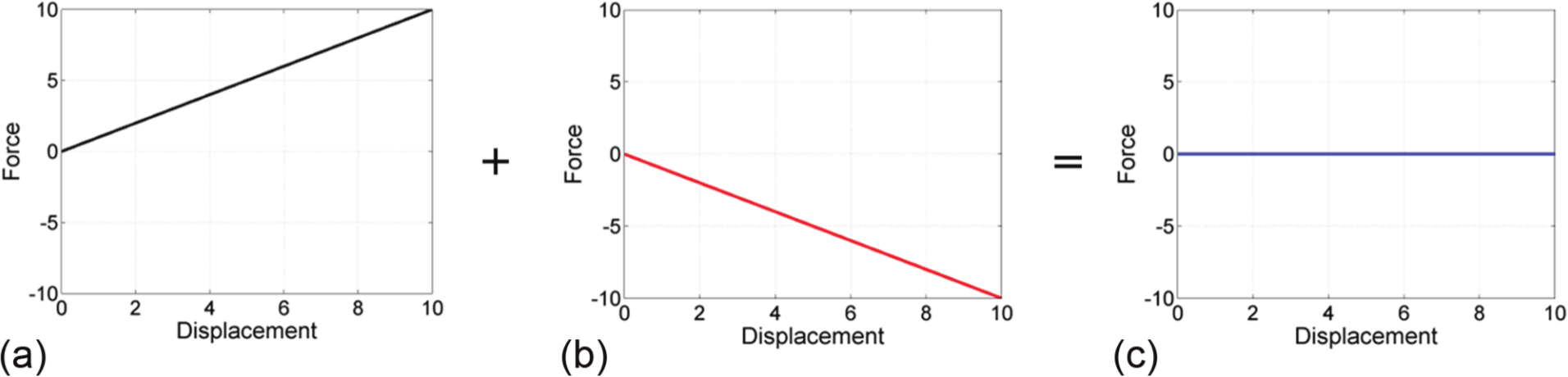
(a) An undesired positive stiffness of a component can be compensated by using (b) a mechanism with a negative stiffness. (c) The result is a mechanism that can move with a zero stiffness.
Although there exists no spring with a negative stiffness, it is possible to create a negative stiffness by using a tension spring with a positive stiffness, together with two bars and three joints (Figure 2). When angle α increases, the spring moves away from the joint axis and the moment arm increases. At the same time, the spring shortens, which results in a decreasing force in the tension spring. The moment in the joint (Mspring) is the product of the moment arm and the spring force. It is possible to choose the parameters, for example, spring stiffness, spring dimensions and spring configuration, in such a way that the joint moment decreases when the angle displacement increases. In this way, the slope of the resulting curve will be negative, which means that such a mechanism has a negative stiffness.
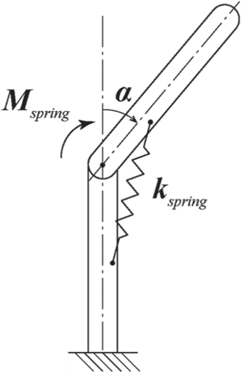
Schematic example of a negative stiffness spring mechanism. A tension spring with stiffness kspring exerts a torque Mspring to the upper bar. When the right spring parameters have been selected, the joint torque decreases as the joint angle α increases.
Protocol
To compensate the parasitic glove stiffness in a finger joint, the following steps were followed:
The parasitic glove stiffness in the finger joint was measured, together with the required input torque and the energy dissipated by the glove. The glove was placed on the set-up and the finger was flexed from 0° to 90° and extended again.
The measured force–displacement curve was fit with a linear approximation to approach the glove stiffness.
The different feasible configurations of the compensation mechanism were modelled.
The optimal solution was selected.
The selected solution was implemented.
The resultant stiffness in the finger joint was measured.
Test set-up
A finger frame was placed inside the finger joint to measure the joint stiffness (Figure 3). In this study, the metacarpophalangeal (MCP) joint of the index finger was used. The finger frame consisted of two bars connected with a joint. The joint had ball bearings to minimize the joint friction in the finger frame. A cable running over a pulley controlled the joint angle. One end of the cable was attached to the measurement set-up. The measurement set-up activated the cable and measured the cable force and displacement. The other end of the cable was attached to a counter mass, which returned the finger joint to its initial position. The thumb of the glove was moved sideways out of the trajectory of the index finger to avoid collision. The extension force applied by the counter mass was subtracted from the cable force. The resulting force, or activation force, was multiplied by the pulley radius to obtain the activation torque, which was recorded for every joint angle.
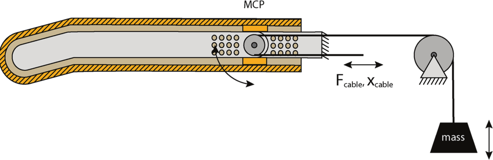
Test set-up to measure the joint stiffness. The finger was flexed by pulling the cable. The cable force and displacement were recorded. The counter mass extended the finger when the cable was released. The extension force applied by the counter mass was subtracted from the cable force. The mechanism was also used as a stiffness compensation mechanism by placing two pins in the holes at the left and right sides of the joint and by attaching a spring to those pins (see Figure 5).
Gloves
For the test, two different cosmetic gloves were used, a silicone cosmetic glove (type: SG302/E4) and a PVC cosmetic glove (type: CG302/E4). Both gloves were manufactured by RSLSteeper (Figure 4) and had identical shape and size.
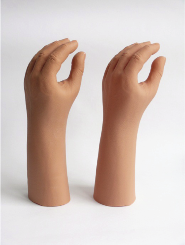
The RSLSteeper cosmetic gloves that were used in this study, the PVC glove (left) and the silicone glove (right).
Compensation mechanism
The finger frame of the test set-up was used as a compensation mechanism by attaching a helical tension spring to the frame. Above and below the joint, there were 12 spring attachment points in a grid of 3 × 4. This enabled 12 × 12 = 144 different configurations. The distance between the centres of the holes was 3 mm. The distance from the first row to the joint centre was 6 mm. A pin could be placed in one of the holes to serve as a spring attachment point (Figure 5). The forces acting on the distal phalanx, when a spring was applied, are shown in Figure 6. Spring manufacturers offer many different springs. Important spring parameters are the following: spring stiffness, rest length, maximum elongation, spring diameter and wire diameter. As the spring had to fit inside a finger, along the finger frame, the maximum spring diameter was set at 5 mm. Because a prosthetic hand has to function in a moist environment (e.g. ambient humidity or seepage from immersion of the hand), the springs had to be made of stainless spring steel. From the product range of standard helical springs of a large spring manufacturer (www.alcomex.nl), a total of 52 springs met both criteria.
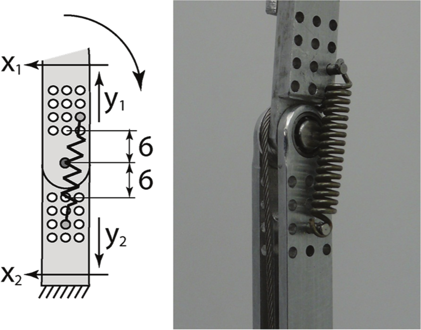
There were 3 × 4 × 3 × 4 = 144 different configurations to attach the spring to the mechanism. The distance between the centres of the joint was 3 mm. The curved arrow indicates the direction of the joint flexion. The figure shows configuration x1 = 1, y1 = 2, x2 = 2, y2 = 3, both (a) schematically and (b) on the real mechanism.
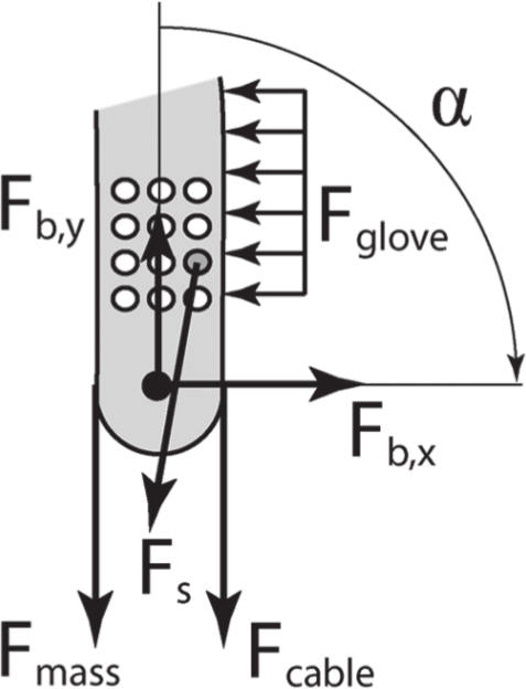
Forces acting on the distal phalanx, inducing torques around the joint axis. The forces of the cosmetic glove (Fglove) and the extension force of the counter mass (Fmass) induce a counter clockwise or positive torque. The cable force (Fcable) and the force of the compensation spring (Fs) induce a clockwise or negative torque. Fb,x and Fb,y represent the reaction forces in the joint, which do not contribute to the torque. The range of motion of the phalanx is indicated by arrow α.
MATLAB model
A model was created in MATLAB to select the optimal spring together with the optimal spring configuration. The parameters of the 52 selected springs were included in the model. The model calculated the force–displacement curve for every spring in every configuration. The force–displacement curve of the compensation mechanism was added to the curve of the glove to calculate the resultant curve (Figure 1). In the final step, the algorithm selected the resultant curve that had the smallest deviation from the horizontal axis. This is the combination of spring and attachment configuration that requires the lowest input torque.
Results
Figure 7 shows the measured joint torque as a function of the angle for one cycle of 90° flexion and extension of both gloves. The torque increased almost linear with the joint angle. The area enclosed by the entire curve represents the amount of energy dissipated by the glove during one cycle. When the PVC glove was applied, the finger required a torque range of 193 Nmm (from a minimum torque of −77 Nmm to a maximum torque of 116 Nmm). During one cycle, 69 Nmm or mJ of energy was dissipated. The silicone glove required a torque range of 73 Nmm (from −33 Nmm to 40 Nmm). During one cycle, 27 Nmm or mJ of energy was dissipated. Figure 7 shows the linear approximation of the joint stiffnesses of both gloves. The linear approximation of the joint torque and the joint angle θ (in degrees) could be described by MPVC = −72 + 2.07θ for the PVC glove and by MPVC = −29+0.73θ for the silicone glove.
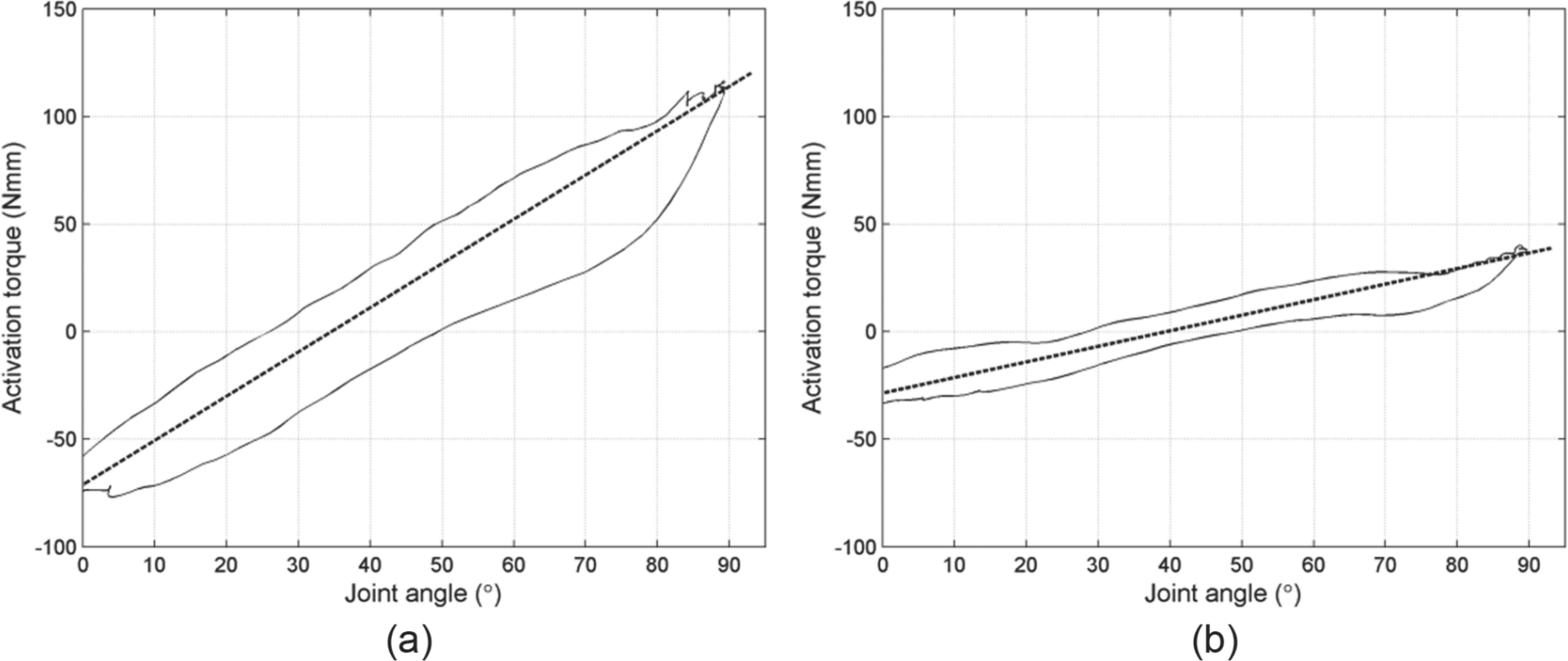
Measured joint stiffness (black line) and linear approached stiffness (dashed linear line) of (a) the PVC glove and (b) the silicone glove. The diagram represents one cycle of 90° flexion and extension. The difference between the minimum and the maximum measured torque was 193 Nmm for the PVC glove and 73 Nmm for the silicone glove.
To compensate the stiffness of the PVC glove, the MATLAB model predicted the optimal result for TR480 spring (Alcomex.nl) in the configuration x1 = 1, y1 = 2, x2 = 1, y2 = 2. In this configuration, the system dissipated 37 Nmm or mJ of energy. For the silicone glove, the optimal compensation was predicted for the TR390 spring in the configuration x1 = 1, y1 = 1, x2 = 1, y2 = 4. Figure 8 shows the predicted characteristic of the spring, together with the measured characteristic. In this configuration, the system dissipated 21 Nmm or mJ of energy.
The predicted (dashed line) and the measured (solid line) characteristic of the suggested spring installed on the compensation mechanism in its optimal configuration. (a) The TR480 spring for compensation of the PVC glove. (b) The TR390 spring for compensation of the silicone glove. The diagram represents one cycle of 90° flexion and extension.
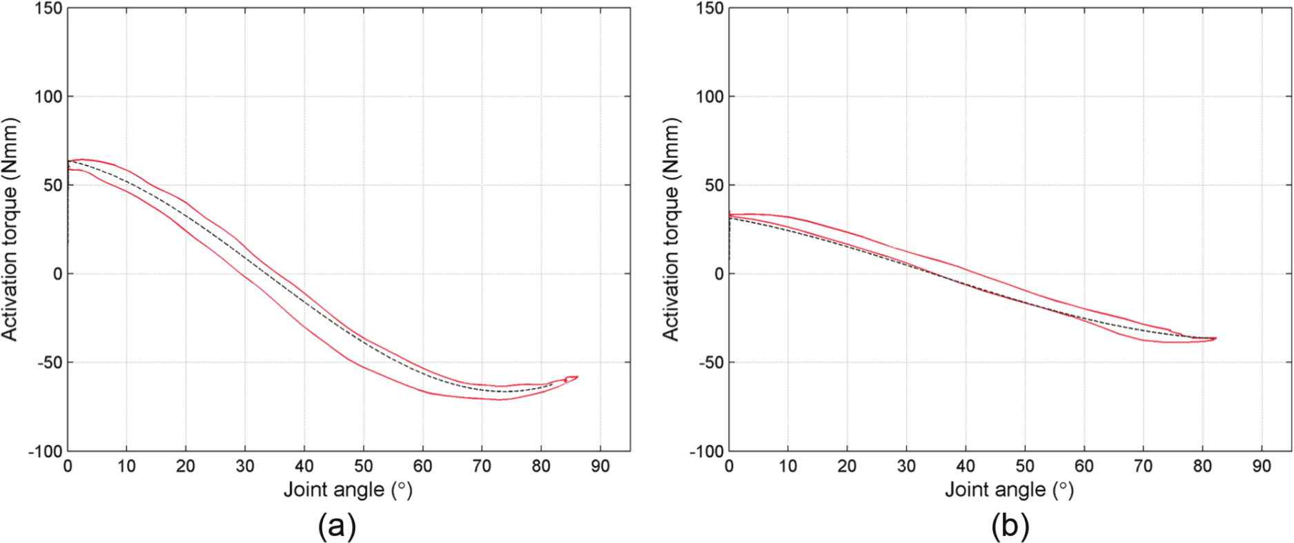
Figure 9 shows the resultant characteristics of the joint of both fingers, with the spring and the glove applied. The PVC glove in combination with the compensation mechanism required a torque range of 81 Nmm (from a minimum torque of −36 Nmm to a maximum torque of 45 Nmm). This is 42% of the required torque range of the uncompensated glove. During one cycle, 67 Nmm or mJ of energy was dissipated. The silicone glove in combination with the compensation mechanism required a torque range of 35 Nmm (from −10 Nmm to 25 Nmm), which is 48% of the required torque range of the uncompensated glove. During one cycle, 28 Nmm or mJ of energy was dissipated.
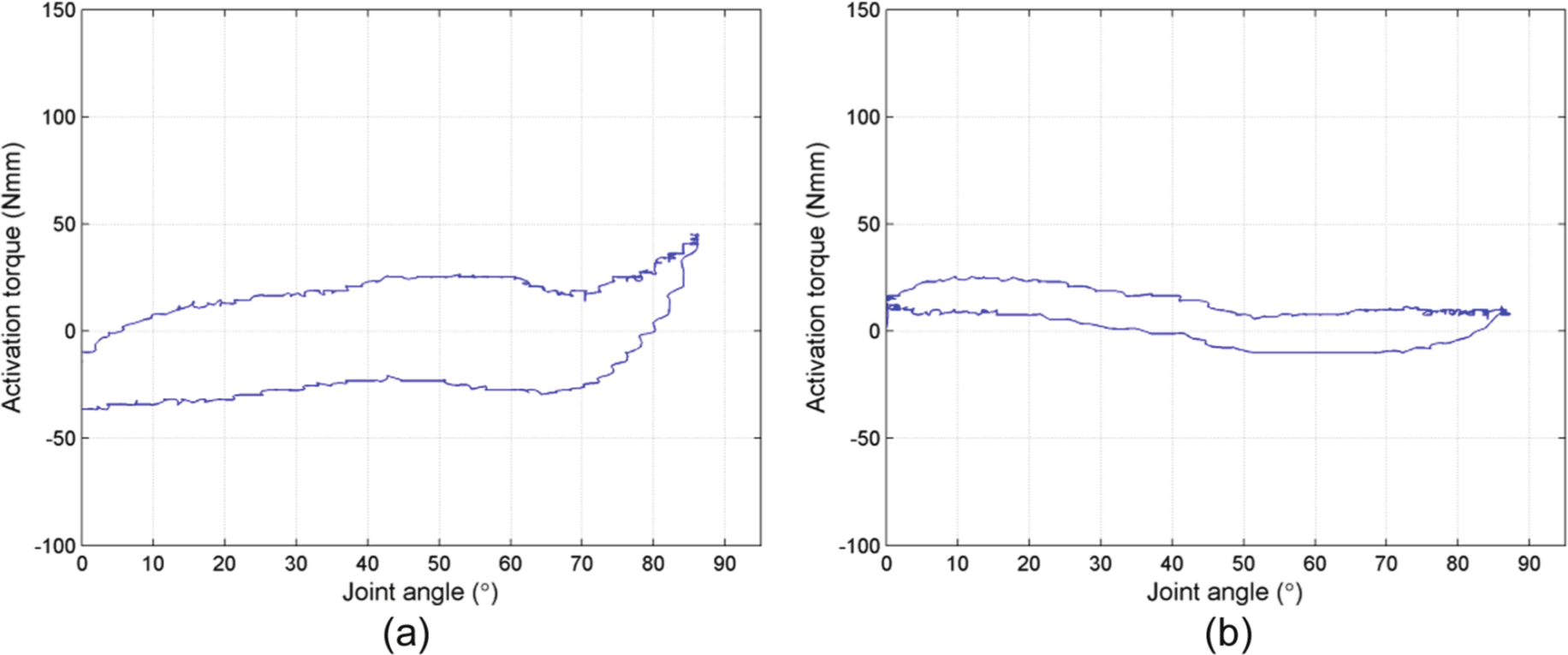
The resultant torque characteristic after the glove was placed over the finger. The difference between the minimum and the maximum measured torque was 81 Nmm for the (a) PVC glove and 35 Nmm for the (b) silicone glove. This is a reduction by 58% and 52%, respectively, compared to the uncompensated glove.
Discussion
This study showed that it was possible to compensate the undesired joint stiffness caused by the cosmetic glove. The compensation mechanism reduced the required joint torque range of the PVC glove by 58% and of the silicone glove by 52%. However, it was not possible to achieve a perfect compensation, as in Figure 1(c). First, the glove stiffness was linearly approached. The real glove characteristic was, however, not entirely linear and also had a considerable amount of hysteresis (Figure 7). Second, the real spring compensation characteristic might also have deviated a little from the measured characteristic (Figure 8(b)), as the spring properties usually slightly differ from the properties specified by the manufacturer. In addition, the spring mechanism added a small amount of hysteresis. Third, the optimal calculated resultant characteristic (Figure 9) was not exactly zero for every joint angle due to the limited amount of springs and spring attachment locations. Despite these inaccuracies and hysteresis, the input torque was considerably reduced.
Implications for prosthetic hands
The mechanism can be applied to both body-powered and electric-powered hands. In electric-powered hands, the compensation mechanism will help to reduce power consumption. Furthermore, it might be possible to select other electric motors, which have a lower mass. Excessive prosthesis mass is currently one of the most important factors in prosthesis rejection. 8 Finger movement requires a fast movement at a low torque, and pinching requires a small movement at a high torque. Bi-phasic systems9,10 and systems with ‘synergetic prehension’11,12 use this property to reduce the motor mass and required energy. When the torque is reduced by the glove compensation mechanism, these systems could be optimized to even further reduce energy consumption and to obtain a small reduction in motor mass. However, the real benefit of the compensation mechanism will be for body-powered prostheses, as in these hands, the user of the hand has to deliver the input energy himself. In many current hands, this is a problem as the forces the user has to deliver are too high. 4 Applying the compensation mechanism to a prosthetic hand will help to reduce the force that the user has to deliver.
The study showed that the undesired stiffness of the cosmetic glove can be compensated by a relatively simple mechanism. All that are needed are a spring, the attachment points and a small build-in space. The mechanism works for individual fingers, and every single finger can be compensated. When applying the mechanism to a prosthetic hand, the biggest challenge will be the limited build-in space inside the finger. Other aspects, for example, costs and mass, will be of minor influence. Because of the small number of extra required parts and the low mass of the parts (less than 1 g per joint), the glove compensation will only add little extra mass, relative to the mass of a standard prosthetic hand (~500 g).
Inner glove compensation?
Beside a cosmetic glove, many prosthetic hands also have an inner glove. The inner glove gives the hand its shape, and it provides an extra protection of the mechanism against the environment. From a mechanical point of view, the inner glove has the same undesired properties as the cosmetic glove. The inner glove is even thicker and stiffer than the cosmetic glove, and therefore, it dissipates more energy than the cosmetic glove and it requires a higher input force. 4 Although it might also be possible to compensate the stiffness of the inner glove, this will be harder to achieve due to its higher stiffness. However, the use of an inner glove is not a necessity. Hands like the Becker Imperial hand or the Hosmer APRL hand do not use an inner glove. In addition, new hands like the i-limb® and the bebionic do not use inner gloves. Because of its negative mechanical properties, the use of an inner glove should be avoided in future designs. 4 Omission of the inner glove will also leave more build-in space for the compensation mechanism.
Other applications
This study was performed to solve the problem of the undesired stiffness of finger joints of prosthetic hands, caused by the cosmetic glove. The presented solution can, however, be used for every joint, which has an undesired joint stiffness, for example, a bundle of cables or a hydraulic hose attached to a joint of a robot arm.
Strengths and limitations
Although the glove compensation principle was already described in earlier studies,2,6,7 it was still unknown whether it would be feasible to design a mechanism that would fit inside a prosthetic hand. This study showed that it was even possible to fit such a mechanism inside a finger. The mechanism used standard springs and was adjustable to different gloves, even when the gloves were made of different materials and had different stiffness characteristics. This enabled the use of different gloves, which is important as there are various different glove manufacturers who produce a broad range of PVC and silicone cosmetic gloves of different sizes and thicknesses.
The most important limitation of the compensation mechanism was the hysteresis band, which was largely caused by the hysteresis in the glove. The compensation mechanism added a small amount of extra friction. As a result of the hysteresis band, the system always needed an input torque and always dissipated energy during motion. A strength of the presented compensation mechanism is that it only required two extra joints (the attachment points of the spring) so that the added amount of joint friction was small.
Conclusions
This study showed that the undesired positive stiffness in the joint of the cosmetic glove can be compensated with a relatively simple negative stiffness mechanism by using a standard helical tension spring. The mechanism was designed, built and tested. The entire mechanism fit inside a finger of a standard cosmetic glove. The mechanism could compensate the positive stiffness of a silicone cosmetic glove as well as a much stiffer PVC glove. The compensation mechanism reduced the required input torque range by 58% for the PVC glove and by 52% for the silicone glove. The addition of the compensation mechanism did not significantly change the total energy dissipation of the finger joint.
Footnotes
Conflict of interest
The authors declare that there is no conflict of interest.
Funding
This research received no specific grant from any funding agency in the public, commercial, or not-for-profit sectors.