
Abstract
Background:
Upper limb amputees have no direct sense of the grip force applied by a prosthetic hand; thus, precise control of the applied grip force is difficult for amputees. Since there is little object deformation when rigid objects are grasped, it is difficult for amputees to visually gauge the applied grip force in this situation.
Objectives:
To determine if the applied grip force from a prosthetic hand can be visually displayed and used to more efficaciously grasp objects.
Study Design:
Experimental controlled trial.
Methods:
Force feedback is used in the control algorithm for the prosthetic hand and supplied visually to the user through a bicolor LED experimentally mounted to the thumb. Several experiments are performed by able-bodied test subjects to rate the usefulness of the additional visual feedback when manipulating a clearly visible, brittle object that can break if grasped too firmly. A hybrid force-velocity sliding mode controller is used with and without additional visual force feedback supplied to the operators.
Results:
Subjective evaluations and success rates from the test subjects indicate a statistically significant reduction in breaking the grasped object when using the prosthesis with the extra visual feedback.
Conclusions:
The additional visual force feedback can effectively facilitate the manipulation of brittle objects.
Clinical relevance
The novel approach of this research is the implementation of a noninvasive, effective and economic technique to visually indicate the grip force applied by a prosthetic hand to upper limb amputees. This technique provides a statistically significant improvement when handling brittle objects.
Background
Powered upper limb prostheses have been beneficial to amputees, but still have several problems that limit their performance.1–4 Sometimes objects grasped by prosthetic hands slip free and fall. 5 This is caused in part because the user is not fully aware of the grip force applied by the prosthesis. Otto Bock has incorporated an embedded three axis force sensor into the thumb of their SensorHand to help prevent unintentional slip of grasped objects.6,7 Another way to prevent slip of grasped objects is to have more contact points with the objects. This is one reason that five digit research-based and commercially available prostheses such as the i-Limb, 8 the Spring Hand, 9 the Michelangelo Hand, 10 the SmartHand 11 and the bebionic hand (RSL Steeper) are being developed. The bebionic hand also has autonomous grasped object slip prevention capabilities.
However, five digit prostheses do little to solve another problem encountered by amputees who use prosthetic hands which is the lack of feedback to the user about the state of the hand.1,2 When grasping a rigid or brittle object, it is difficult to visually ascertain the amplitude of applied grip force because rigid objects undergo imperceptible deflections from typical grip forces. This means that there is often little warning before a brittle object is accidentally broken or dropped. Because a natural sense of contact force is quite important, 12 supplemental grasp force feedback can improve force control even when the user has clear sight of the manipulated object. 13 There have been many different techniques employed to reconnect a sense of contact force to amputees. Direct neural feedback of grip force from a prosthetic hand has been demonstrated with amputees.14–16 A proportional force feedback system was developed that applies a force to the skin of the amputee in proportion to the magnitude of the applied grip force by the prosthesis. 17 Electrical stimulation of the skin has been used to indicate a change in applied grip force through a change in frequency of electrical pulses. 18 Vibrotactile feedback has been supplied to amputees whereby the applied grip force is conveyed to the user through a change in vibration frequency. 19
However, documentation exists of instances in which vibrotactile feedback for extended periods of time can be disturbing. 19 Electrical stimulation of the skin can be painful or unpleasant if the current amplitude is slightly too large and direct neural feedback is still impractical for clinical implementation over long periods of time.
In this paper, the Motion Control Hand (Motion Control, Inc., Salt Lake City, UT) is used for experiments to manipulate a rigid object with and without additional force feedback supplied visually to the user. Force feedback is used in this research in two different ways. The first is that the magnitude of the applied grip force is mapped to light intensity from an LED. This permits the user to know how tightly a rigid object is being gripped by observing the intensity of the light from an LED experimentally mounted onto the thumb of the prosthesis (Figure 1). The research in this paper represents the first application where an LED is used to proportionally indicate the applied grip force of a myoelectrically controlled prosthesis. However, LEDs have been used in the past for prostheses to convey other information, like battery power level (RehabTech, Caulfield, Australia), and EMG signal amplitude. 20 An LED has also been used in telerobotic operations to indicate if the desired grip force was too low to prevent slip causing a low level controller to intervene. 21
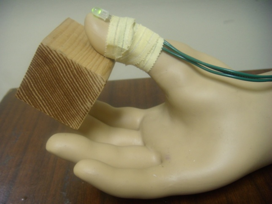
The Motion Control Hand with a red-green bicolor LED experimentally mounted to the thumb to visually indicate the applied grip force.
The second way that force feedback is used in this research is in the sliding mode control algorithm of the hand. A hybrid force-velocity sliding mode controller 22 is used to provide improved control of velocity and force of the prosthetic hand through a single control input. Sliding mode control is a nonlinear control technique that has been used in other areas of biomedical engineering like functional electrical stimulation. 23 Force derivative feedback is also used in the control algorithm as this has recently been shown to increase the grip force sensitivity of prosthetic hands.24,25
Visual force feedback is evaluated in this paper because there are still problems with each of the previously discussed methods of force feedback supplied directly to the user. The purpose of this research is to present results from six nonamputee test subjects who experimentally evaluated an inexpensive and low power method of visually supplying force feedback for prosthetic hands.
Motion Control Hand
The Motion Control Hand (Figure 1) has only one degree of freedom; the fingers are linked to the thumb through a four-bar mechanism so that the hand can simply open or close. The Motion Control Hand has been experimentally outfitted with an A1321 (Allegro MicroSystems, Inc. Worcester, MA) Hall effect position sensor and strain gauges mounted on the thumb. The position sensor indicates the distance between the thumb and forefingers and the strain gauges are used to convey the grip force.
A system model, obtained through a summation of torques acting on the motor, may be used to describe the dynamics of the prosthetic hand:


E is the voltage input to the motor and n is a value dependent upon the motor’s resistance, torque constant and effective inertia. x 1 is the distance between the thumb and fingers and x 2 is the velocity of the hand. ẋ and ẍ are the velocity and acceleration, respectively. The m(x 1 ,x 2 ) term accounts for the inertia (J), damping (B), and stiffness (K) of the system in addition to the nonlinear Coulomb friction (F) produced by the large gear ratios:

The sgn function is defined to be one, zero or negative one if its argument is positive, zero or negative, respectively. D is used to describe unknown externally applied disturbance forces and the nonlinear torque transmission through the four-bar linkage mechanism.
Sliding mode controller
Sliding mode control is a technique that is often used to overcome nonlinear forces inherent to prostheses22,23,26 and for many different applications like functional electrical stimulation.23,27–30 In this paper, sliding mode control of the prosthetic hand is incorporated into a hybrid force-velocity control scheme 31 so that the user has improved control of the velocity or force of the prosthesis through a single input. The sliding mode controller works by fully saturating the motor of the prosthesis positively or negatively while there is an error present in the desired force or velocity. The switching of the motor voltage is dependent on the force, position and velocity of the system.
Sliding mode control is typically realized through an input of the form

where s, the sliding manifold, is a function of force and position error. C is a value based on an upper-bound estimate on the torques and disturbances acting against the motor of the prosthetic hand. The sliding mode controller in this paper, however, uses the saturation function in place of the sgn function to partially linearize the control law and prevent unwanted chatter of the hand (Figure 2). Specific details of this controller, a controller derivation, and a robustness analysis have been previously presented. 22 Force derivative feedback is also used to improve the transition from velocity to force control. 24
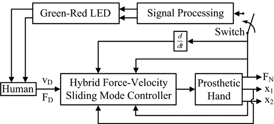
Hybrid force-velocity sliding mode controller with force, force derivative, position, and velocity feedback. FD is the desired force, vD is the desired velocity, FN is the measured normal force, x1 is the position, and x2 is the velocity. The switch can be toggled to on or off to enable additional visual force feedback to the user.
Enhanced visual feedback
To help people manipulate rigid objects with the prosthesis, an LED was experimentally mounted to the thumb of the Motion Control Hand to convey the applied force to the user through a change in light intensity and color. A red/green bicolor LED was used to effectively double the resolution of the visual feedback. The color scheme is also fairly intuitive as it is similar to traffic lights. Increasing green light is used to indicate small levels of grip force. When the applied grip force exceeds 25 N, the red light turns on and begins to increase in intensity. The visual feedback has two frequency components, only green when the grip force is below 25 N, and fully saturated green superposed with red when the grip force is larger than 25 N. (25 N was chosen to be the transition threshold in this research for consistency among test subjects; however, this level is adjustable by the user in general). The mathematical relationship for the bicolor LED output as a function of intensity and wavelength is shown in Figure 3.
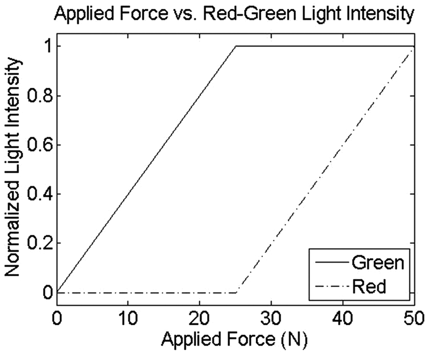
Relationship between the measured applied grip force and the red-green light intensity. The light intensity of each LED displayed in the figure is normalized by the maximum possible light intensity level.
The enhanced visual feedback is used in conjunction with the hybrid force-velocity sliding mode controller as shown in Figure 2 when the switch is closed. This enables the LEDs to visually indicate the applied grip force.
Methods
Six nonamputee test subjects (one female, five male) who were aged between 20 and 35 years gave informed consent to participate in this study. Ethical approval was sought for this research and granted under IRB protocol number 13459. Myolab II (Motion Control, Inc.) was used to amplify and rectify the EMG signals of the test subjects. EMG signals were also digitally sampled at 1 kHz and filtered online in Simulink (The MathWorks, Natick, MA) with a first order low pass filter that had a cutoff frequency of 62.3 rad/s. However, most of the EMG signal amplification is done at the muscle site by dual channel EMG preamplifiers. One dual-site preamplifier was placed over the flexor carpi radialis muscle 32 and another was placed over the extensor digitorum communis muscle to create a dual polarity motor command signal for the prosthesis.
To quantify the usefulness of additional visual feedback, the six nonamputee test subjects were asked to manipulate a rigid mechanical ‘egg’ (Figure 4). 17 The test subjects opted to use their right hands to hold the prosthetic hand apparatus 25 and to have the EMG preamplifiers placed on their left forearms to control the prosthesis. The mechanical ‘egg’ is similar to a real egg because no visual deflection of the ‘egg’ is perceptible before it breaks. This type of object manipulation can pose a difficult challenge for human operators because the amount of grip force actually applied by the prosthesis is typically unknown to the user. The mass of the ‘egg’ was made to be 1.235 kg; the force required to break the ‘egg’ was set to be 28.7 N. The minimum grip force required to lift the ‘egg’ was 23.4 N. This combination of ‘egg’ mass and break force was chosen to create a moderately challenging range of possible grip forces that can be applied to successfully lift, without breaking, the ‘egg.’ The force required to break the ‘egg’ relates to a fully saturated level of green light superposed atop a low level of red light.
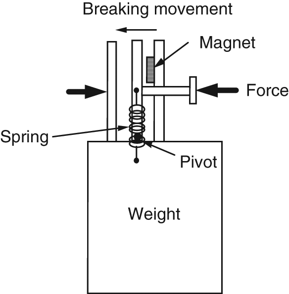
Diagram of the mechanical ‘egg’ used in the experiments.
All six of the test subjects were first asked to lift and break the mechanical ‘egg’ with their natural hands to gain a feel for the ‘egg’. Then, the test subjects were given ten minutes to become comfortable with sliding mode control of the Motion Control Hand. During this time, the test subjects were also asked to practise lifting the ‘egg’ 10 times with the prosthesis with and without the additional visual feedback and to learn the relationship between the applied grip force and the LED output. The test subjects were then asked to lift, without breaking or dropping, the mechanical ‘egg’ 15 times with the prosthesis both with and without the additional visual force feedback. Test subjects 1, 2 and 3 started without the additional visual feedback first while test subjects 4, 5 and 6 started with the visual feedback first. The number of successes and failures with each controller were recorded. A failure occurred if the ‘egg’ was broken or dropped. No time constraint was imposed upon the test subjects to perform each trial.
Finally, test subjects were asked to subjectively evaluate each control technique. The sliding mode controller without additional visual feedback was defined to be a 5 on a scale of 1 to 10. A 1 indicated ‘very difficult to complete the task’ and a 10 indicated ‘very easy to complete the task’. Test subjects were then asked to rate the enhanced visual feedback sliding mode controller on the same scale of 1 to 10 relative to the 5 assigned to the sliding mode controller without the additional visual feedback. The sliding mode controller was implemented in MATLAB/Simulink with a control loop sampling frequency of 1 kHz.
The relative significance of the human experimental results was analyzed in MATLAB. The ANOVA2 function was used to perform a two-way analysis of variance (ANOVA) on the ‘egg’ break results obtained with and without additional visual feedback. The two-way ANOVA test indicates whether the differences between the two control methods and the six test subjects are statistically different. The ranksum function was used to perform a two-sided nonparametric Mann-Whitney U-test on the subjective evaluations given by the test subjects. The U-test examines the hypothesis that two sets of data come from distributions with equal medians. The two sets of data are assumed to come from identical and continuous distributions with a possible location shift, but are otherwise arbitrary. For this reason, the U-test is well suited to analyze subjective evaluations. The ranksum and ANOVA2 functions calculate p-values to indicate whether or not the additional visual feedback is statistically significant.
Results
The number of times the ‘egg’ was successfully lifted by each test subject is shown in Figure 5. Except for test subject 2, each person had a better success rate with the additional visual feedback than without. Test subject 2 had the same success rate with and without the additional visual feedback. The two-way ANOVA test shows a statistically significant difference between the performances of the test subjects (p = 0.04). The ANOVA test also shows a significant difference in the ‘egg’ break success rates obtained with and without additional visual feedback (p = 0.03).
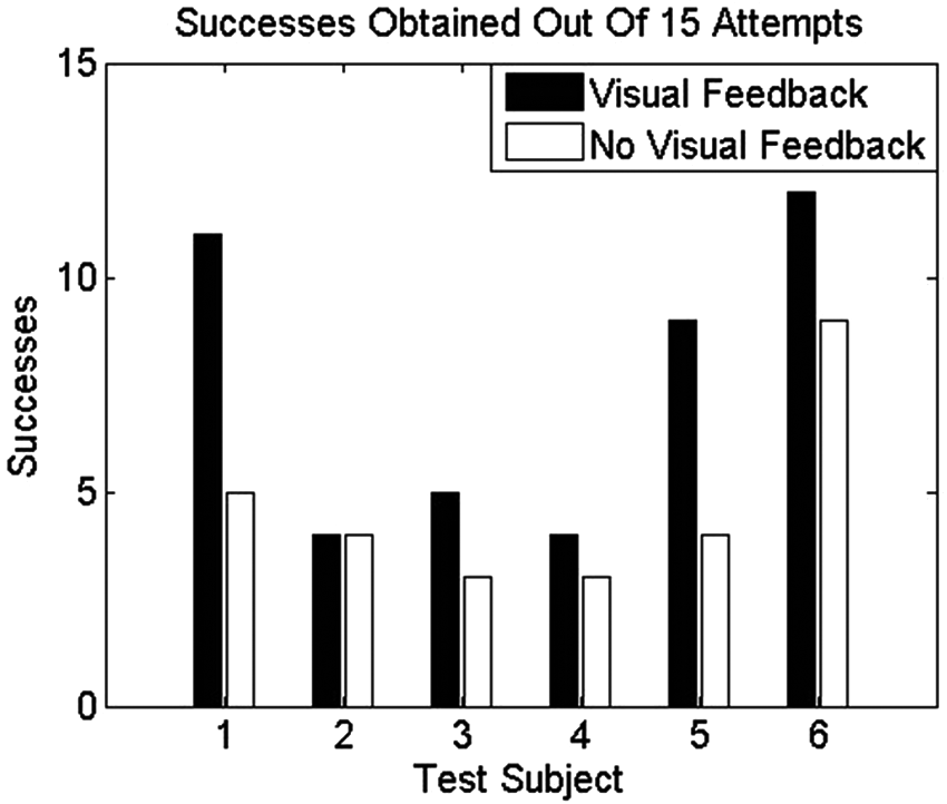
Success rates from each individual test subject with and without additional visual feedback. Test subjects used the prosthesis to lift the mechanical ‘egg’ 15 times with each controller.
The subjective evaluations of each test subject also indicate a favorable improvement with the additional visual feedback (Figure 6). With the exception of test subject 5, each person subjectively evaluated the additional visual force feedback higher than the case without the LED attached to the prosthesis. For this reason, the average subjective evaluations with the additional visual feedback are also better with the visual feedback (Figure 7). The nonparametric U-test shows a statistically significant difference between the subjective evaluations of the six nonamputee test subjects with regard to the two control methods (p < 0.05).
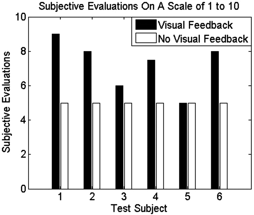
Subjective evaluations on a scale of 1 to 10 from each test subject with and without the additional visual feedback.
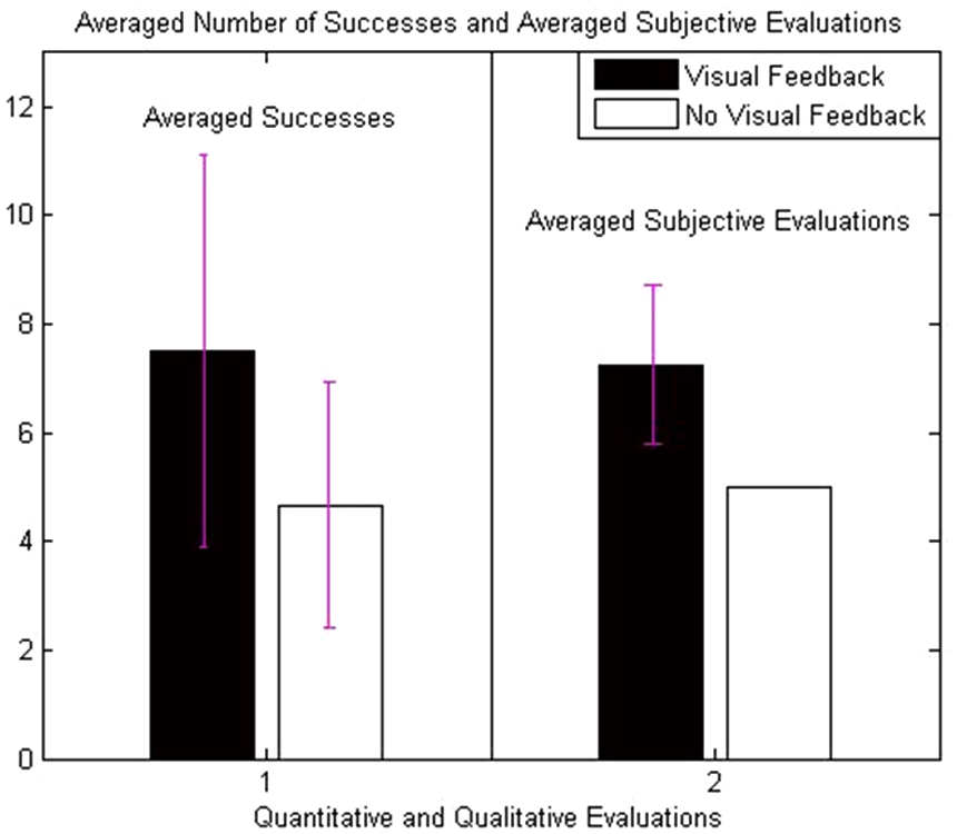
Average and standard deviation of the quantitative and qualitative results from six test subjects. A statistically significant difference exists between the method of additional feedback compared to the case without additional visual feedback. The statistical difference is present both for the subjective evaluations (p < 0.05) and for the success rates (p < 0.05).
Discussion
The two-way ANOVA indicates that there was a significant difference in the success rates between test subjects. This shows that some test subjects benefited more than others from the additional visual feedback. This is corroborated indirectly by the subjective evaluations which show that some test subjects rated the additional visual force feedback higher than others.
The two-way ANOVA also shows that the additional visual feedback produces a statistically significant difference in success rates achieved with the two control methods. From the improvement in average success rates (Figure 7) coupled with the results from the ANOVA test, it is clear that the additional visual feedback enabled the test subjects to more successfully manipulate, on average, a clearly visible rigid object.
These results indicate that the additional visual force feedback is a useful and effective method to display the applied grip force of a myoelectrically operated prosthesis.
There have been many previously documented techniques to supply grip force feedback to amputees in the past, all of which have problems associated with them as previously discussed. The method of enhanced visual force feedback presented in this paper has two main drawbacks: the user must look at the force-indicating LEDs to benefit, and the additional visual feedback may be perceived as unnatural. However, when lifting and manipulating delicate objects, visual attention is typically required even when using the natural hand 33 . So, the gaze of the prosthesis operators will usually be directed toward the LED mounted on the thumb when grasping objects anyway. The second drawback could easily be circumvented with a LED power switch to turn off the additional visual feedback whenever desired. Other than these two minor drawbacks, the method of enhanced visual feedback has many positive attributes.
In particular, the additional visual force feedback proposed in this paper produces no physical discomfort, is highly economic, has no moving parts, is compact in size, requires very little power to function, is light weight and only requires simple circuitry that could be easily contained entirely within a prosthetic hand.
Nonamputee test subjects with little experience operating a prosthetic hand were used in this study and the additional visual force feedback was useful for them. This is a similar situation to amputees who are initially fitted with a prosthetic hand. Hence, it is believed that the visual force feedback would be useful to help amputees to more quickly learn to effectively control the applied grip force. This improvement could also help reduce the rate that prosthetic hands are rejected for use by amputees as the initial learning curve would be less frustrating. Furthermore, because rigid objects experience no perceptible deformation when squeezed, even the most experienced prosthetic hand operator cannot always know the applied grip force with absolute certainty. Thus, the method of additional visual feedback described in this paper could be useful to experienced and inexperienced prosthetic hand operators to decrease the frequency of dropping and breaking objects. Further testing with experienced amputee test subjects is required to validate the efficacy of the enhanced visual feedback after the initial training phase. It would also be useful to survey the experienced amputee test subjects about the aesthetics of the LED once it has been properly incorporated into a cosmetic glove. At present, the method of mounting the LED to the exterior of the cosmetic glove is insufficient for daily use by amputees which is the prime reason that nonamputee test subjects were recruited for this research.
Conclusion
This paper has described an inexpensive, light weight, and low power method of visually supplying force feedback to people who use powered prosthetic hands. Grip force feedback is proportionally mapped to light intensity and color through a bicolor LED mounted to the thumb of a prosthetic hand. Experimental results from test subjects who lifted a brittle mechanical ‘egg’ show a statistically significant improvement when additional visual feedback is present even when the user has clear sight of the grasped object. The subjective evaluations of the sliding mode controller with and without enhanced visual feedback also indicate a statistically significant improvement with the LED mounted to the thumb of the prosthesis. The robust, economic and practical method of additional visual force feedback makes this application well suited to prosthetic hands.
Footnotes
Funding
This research was supported by NSF Grant 0457193.
Conflict of interest
The authors declare that there is no conflict of interest.