
Abstract
Background: Calculation of lower limb kinetics is limited by floor-mounted force-plates.
Objectives: Comparison of hip joint moments, power and mechanical work on the prosthetic limb of a transfemoral amputee calculated by inverse dynamics using either the ground reactions (force-plates) or knee reactions (transducer).
Study design: Comparative analysis.
Methods: Kinematics, ground reaction and knee reaction data were collected using a motion analysis system, two force-plates, and a multi-axial transducer mounted below the socket, respectively.
Results: The inverse dynamics using ground reaction underestimated the peaks of hip energy generation and absorption occurring at 63% and 76% of the gait cycle (GC) by 28% and 54%, respectively. This method also overestimated by 24% a phase of negative work at the hip (37%–56% GC), and underestimated the phases of positive (57%–72% GC) and negative (73%–98%GC) work at the hip by 11% and 58%, respectively.
Conclusions: A transducer mounted within the prosthesis has the capacity to provide more realistic kinetics of the prosthetic limb because it enables assessment of multiple consecutive steps and a wide range of activities without the issue of foot placement on force-plates.
Keywords
Introduction
Net joint forces and moments as well as power and work at the ankle, knee and hip of the sound 1 and prosthetic limbs of transfemoral amputees have been used to determine the effects of rehabilitation programmes, 2 – 3 prosthesis alignment 4 – 6 and prosthetic components. 7 – 11
Inverse dynamics
The most comprehensive method to compute these variables relies on well-established inverse dynamic equations. However, several studies have demonstrated that this calculation method presents shortcomings. 12 – 15 It is based on the assumption that rigid segments are linked by ideal joints. It is also sensitive to input data such as inertial parameters, time derivatives, and location of the centre of pressure and the joint centre by means of external markers. Finally, in principle, errors are increasingly propagated upward between ankle, knee and hip. 15
Limitations of floor-mounted force-plates
By definition, the inverse dynamics method requires kinematics and ground reaction forces that are typically obtained using a 3D motion capture system and force-plates, respectively. Most of the limitations associated with the calculation of lower limb kinetics are caused by the experimental conditions when using these instruments, particularly the floor-mounted force-plates.
As indicated by Favre et al., ‘mainly due to the price of the motion capture systems, standard gait laboratories have the capability to measure only a few consecutive steps of ground walking.’ 16 In addition, the sole contact of each foot on a force-plate can be achieved through personalized arrangement of the walking start point and/or force-plate position to avoid targeting and/or repetitive recording of invalid trials. The number of steps analysed depends on the number of force-plates. Some of these limitations can be alleviated using an instrumented treadmill. Nonetheless, relying on anchored equipment is often perceived as a significant technical constraint, particularly when assessing activities of daily living (e.g. ascending and descending stairs and slopes) for lower limb amputees who rely lesson proprioception for foot placement. Thus, the measurements might be only partially reflective of a natural gait.
Benefits of using direct measurement of knee reaction
Several studies have presented an alternative method that can potentially alleviate the limitations mentioned above. In these cases, a multi-axial transducer mountedbelow the residuum of transfemoral amputees fitted with a socket or osseointegrated fixation was used to directly measure the forces and moments applied on the residuum and prosthetic knee. 17 – 19 This apparatus enables load measurement during a large number of gait cycles andactivities such as ascending and descending stairs andslopes. 20 – 21
However, use of a transducer to validate the results of inverse dynamics has received little interest. Only one study has recently done a comparison of the forces and moments measured on the prosthetic knee of a transfemoral amputee during walking, using direct measurement by means of a transducer, versus calculations using three inverse dynamics computations corresponding to three and two segments, and the ground reaction vector technique. 22 These results demonstrated that the differences between direct measurement versus calculation of forces and moments were relatively small. However, this study also showed that the dynamic outcomes of the prosthetic components (i.e. absorption of the foot, friction and limit stop of the knee) were only partially assessed by inverse dynamic methods. Such information is critical to assess all aspects related to construction, and eventually usage, of the prosthesis.
Need for knee reaction measurement to determine hip joint kinetics
The use of a transducer to improve the implementation of inverse dynamics equations is yet to be explored, particularly the possibility of using knee reaction measured by the transducer as dynamic input to determine hip joint kinetics. Indeed, there is a need for an additional comparative study focusing on all aspects of hip joint kinetics (e.g. moments, power and mechanical work).
Such a study is critical because the hip is the only joint the amputee controls directly to set the prosthesis in motion, particularly during the swing phase. Also, the dynamic outcomes of the prosthesis may have a critical impact on the hip. Therefore, in principle, this could provide further clinical information, as hip joint kinetics are potentially associated with joint degeneration, low back pain, risk of falls, etc.
Purpose
The purpose of the present case study was to compare hip joint moments, power and mechanical work on the prosthetic limb of a transfemoral amputee as calculated by inverse dynamics, with either the ground reaction obtained from fixed force-plates, or knee reaction measured directly with a transducer, used as input data.
Methods
Participant
One female transfemoral amputee (36 yr, 1.6 m, 62.6 kg) participated in this study. She provided informed written consent, and the study was approved by the research institution's human ethics committee.
Apparatus
Figure 1 presents a schematic representation of the components of the prosthetic leg, the marker set and alignment, the position and orientation of the socket and transducer coordinate systems, and the angle correction to realign both coordinate systems.
Schematic representation of the components of the prosthetic leg, the marker set and alignment, the position and orientation of the socket (S[MLS, APS, VTS]) and the transducer (T[XT, YT, ZT]) coordinate systems, and angle correction to realign both coordinates systems (θ and ω) on the sagittal and frontal planes Components: A: socket, B: spherical plate, C: transducer, D:pyramidal connector, E: knee, F: ankle Axes: ML: mediolateral, AP: anteroposterior, VT: long.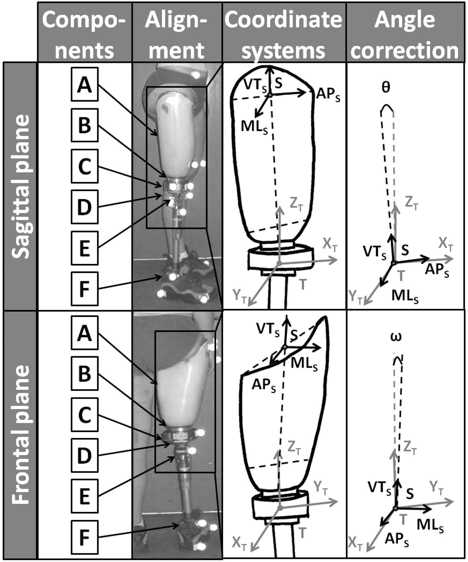
The participant walked with a prosthesis, including an ischial containment socket, a multi-axial transducer (JR3 Inc., Woodland, CA, USA), and her usual knee (Safety knee, Otto-Bock, Vienna, Austria), a solid ankle cushioned heel (SACH foot, Otto-Bock, Vienna, Austria) and footwear. The socket used was specifically manufactured to replicate the internal geometry of the subject’s current socket and to incorporate an adapter attaching the transducer.
Kinematics and ground reaction data were recorded simultaneously with a six-camera Peak-Motus (VICON, Oxford, UK) and two force-plates (AMTI, Watertown, MA, USA) at 50 and 500 Hz, respectively. Double-sided sticky tape was used to place markers on the hip, socket, transducer, pylon and shoe, approximately at landmark levels (i.e. greater trochanter, tibial tuberosity, calcaneum, 5th metatarsal head) and on mechanical parts (i.e. knee axis, ankle fixation).
Knee reaction data was measured and recorded at 200 Hz using a multi-axial transducer similar to that used in previous studies, 17 – 18,20 – 23 and a laptop, respectively. The three components of force and moments were measured with an accuracy greater than 1 N and 1 Nm, respectively. The transducer was attached to the socket using a custom-made spherical plate, and to the knee using a pyramidal connector. The transducer was mounted in such a way that the orientation of its coordinate system (T[XT, YT, ZT]) was roughly aligned with the socket coordinate system (S[MLS, APS, VTS]) corresponding to the local anatomical axes of the residuum (ML: mediolateral, AP: anteroposterior, VT: long). The axes of the residuum were determined as the half point between the rims of the socket in the three planes. Both coordinate systems were re-aligned by means of a transform matrix applied afterwards, created from bench-top measurements.
Recording
First, the prosthetic leg including the transducer was set up and aligned by a qualified prosthetist. The alignment closely replicated the usual one. Approximately 15 min practice with the instrumented prosthetic leg was allowed before recording, to ensure the participant’s confidence, safety and comfort. Then the participant performed 10 walking trials along a 5-metre walkway. The participant was asked to step onto the two force-plates while walking at a comfortable self-selected speed. Sufficient rest was given between trials to avoid fatigue. Finally, the participant doffed the socket, freeing the prosthesis to allow bench-top measurement for the calibration (i.e. zero-offset), realignment of coordinate systems and determination of inertial parameters of the prosthetic components.
Data processing
The raw data were imported into a customized Matlab software program (Math Works Inc., Natick, MA, USA) written to implement the following data processing.
A calibration matrix was applied to both force-plates and to the transducer to eliminate cross-talk and correct the offset of electrical zero. The kinematic data was filtered with a classical 4th order Butterwoth filter at a 5 Hz cut-off frequency. Kinematics and force-plate data were synchronized with the transducer data using the first heel contact on the force-plate as the point ofreference. The inertial parameters of the prosthetic limbwere estimated using residuum volume and bench-topmeasurements for each component. 22 The flexion–extension of the knee prosthesis was estimated functionally using the SARA method as described by Ehrig et al. (2007). 24 The hip joint centre corresponded to the intersection between the line going from the marker on the greater trochanter to the direction of the flexion-extension axis and the long axis of the residuum.
The forces and moments at the hip joint centre were computed for each gait cycle by 3D inverse dynamics 25 using ground reaction at the centre of the pressure level and knee reaction at the joint centre level as input data. The former involved two segments: foot and leg, and thigh. 22 The hip joint moments were expressed in the frontal, axial and sagittal planes in the pelvis coordinate system, representing flexion–extension, internal–external rotation and adduction–abduction, respectively.
The 3D power was obtained by computing the dot product of net moment and joint angular velocity vectors, both expressed in the pelvic coordinate system. The mechanical work was the area under the curve of power. Positive and negative values correspond to generation versus absorption of energy, and to positive versus negative work, respectively.
All the curves of moments and power for each gait cycle were time-rescaled from 0–100 to facilitate the averaging of all trials and reporting of events as a percentage of gait cycle.
Data analysis
The overall analysis relied on the average difference, one standard deviation and root mean square error (RMSE) between the mean curves of hip moments and the power obtained with both inputs during the full gait cycle as well as during support and swing phases. The phase analysis compared the time and value of peaks of hip power and total work obtained with both inputs during the typical phases of generation (H1, H3) and absorption (H2, H4). 9 – 10,26 – 27 The comparison relied on the average and one standard deviation of difference between both inputs (ground reaction minus knee reaction) for each trial, expressed in units or percentages. A positive or negative value corresponded to an underestimation or overestimation, respectively, of the results obtained with ground reaction.
Results
A total of eight trials were considered for analysis. Two trials were discarded during post-analysis of the force-plate data showing that the sole contact of the foot on one plate was doubtful. The participant walked at 1.02 ± 0.01 m/s with a cadence of 48.79 ± 0.61 steps/min. The support and swing phases represented 60.00 ± 1.20% and 40.00 ± 1.20% of the gait cycle, respectively, lasting 1.23 ± 0.02 s.
Moments
The mean hip joint moments are presented in Figure 2. The average differences in mean moments between the two measurement methods on the frontal, axial and sagittal planes of the pelvis were −0.86 ± 2.59 Nm, 0.97 ± 2.42 Nm and 0.91 ± 3.57 Nm during the full cycle, −0.65 ± 3.30 Nm, 2.19 ± 2.45 Nm and 1.43 ± 3.96 Nm during the support phase, and −1.17 ± 0.60 Nm, −0.86 ± 0.27 Nm and 0.12 ± 2.74 Nm during the swing, respectively. The RMSE on the frontal, axial and sagittal planes of the pelvis was 2.71 Nm, 2.59 Nm and 3.66 Nm during the full cycle, 3.34 Nm, 3.26 Nm and 4.18 Nm during the support phase, and 1.31 Nm, 0.90 Nm and 2.71 Nm during the swing, respectively.
Mean hip joint moments in frontal, axial and sagittal planes of the pelvis coordinate system as determined by 3D inverse dynamics using ground reactions at the centre of pressure level, or by knee reactions at joint centre level during a gait cycle HC: heel contact, TO: mean toe-off, GC: gait cycle.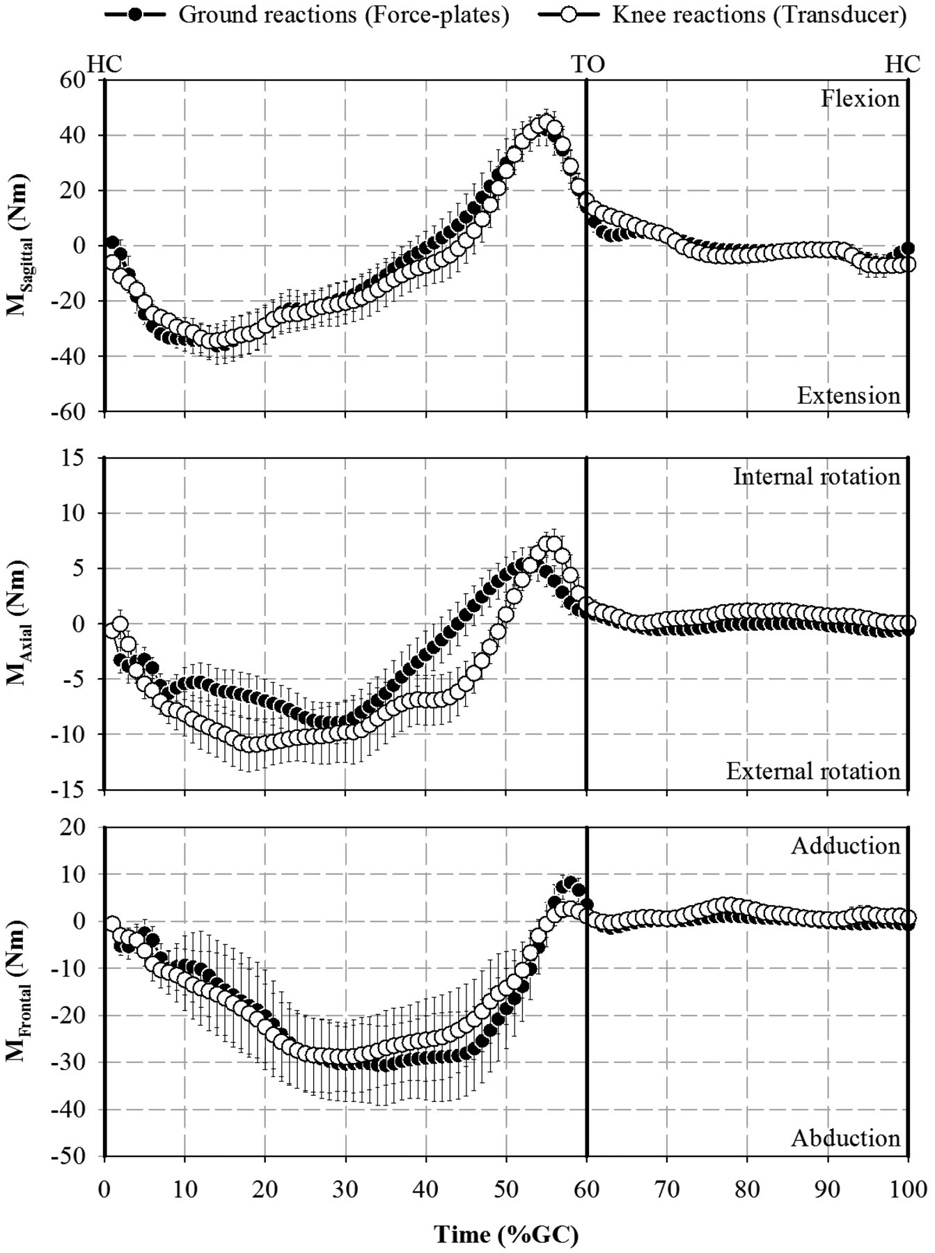
Power
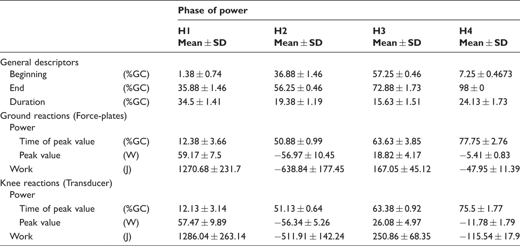
Mean curves of the 3D hip power are presented in Figure 3. The average differences in mean power between the two methods were −1.59 ± 5.72 W, −2.51 ± 5.15 W and −0.2 ± 6.3 W during the full cycle, support and swing phases, respectively. RMSE values for the power were 5.91 W, 5.69 W and 6.23 W during the full cycle, support and swing phases, respectively. Times of occurrence and peak values of the power during each period of generation and absorption are presented in Table 1. The average RMSE between the two methods during phases H1, H2, H3 and H4 were 4.05 ± 0.60 W, 8.82 ± 1.79 W, 9.84 ± 1.77 W and 3.65 ± 0.57 W, respectively. The peak of generation at H1 obtained with inverse dynamics using ground reaction was underestimated by 3.22 ± 2.29% for four trials and overestimated by 9.45 ± 10.37% for four trials. The peak of absorption at H2 was underestimated by 5.70 ± 1.23% for five trials and overestimated by 9.44 ± 7.71% for three trials. The peaks of generation and absorption at H3 and H4 were consistently underestimated by 27.78 ± 9.53% and 53.66 ± 6.21%, respectively.
Mean curves and typical phases of hip power during phases H1, H2, H3 and H4, as determined by inverse dynamics using ground reactions at the centre of pressure level, or by knee reactions at joint centre level during a gait cycle. Positive and negative values corresponded to generation and absorption of energy, respectively. HC: heel contact, TO: mean toe-off. Mean time and value of peak power as well as mechanical work at the hip, as determined by inverse dynamics using ground reactions obtained with a force-plate, or knee reactions obtained with a transducer, during typical phases of generation (H1, H3) and absorption (H2, H4) during gait cycle (GC); positive versus negative values correspond to generation versus absorption of energy, and positive versus negative mechanical work, respectively.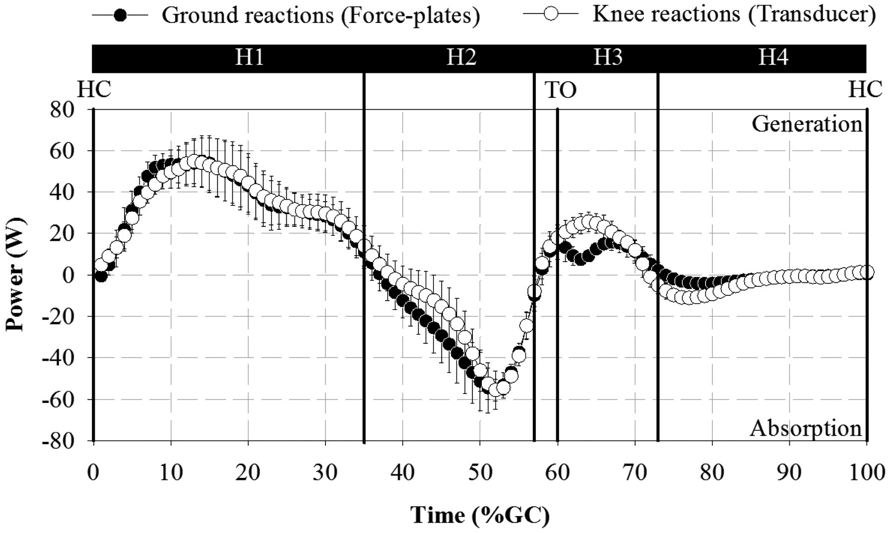
Work
The mean work produced during each phase of power is presented in Table 1. The positive work during phase H1 determined by inverse dynamics using ground reaction was underestimated by 3.98 ± 2.54% for five trials and overestimated by 4.95 ± 4.61 % for 3 trials. The negative work during phases H2 and H4 were consistently overestimated by 23.37 ± 7.50% and underestimated 58.08 ± 9.28%, respectively. The positive work during phase H3 was consistently underestimated by 11.08 ± 0.31%.
Discussion
Limitations
The scope of this case study was to compare the hip joint kinetics obtained with ground reaction (force-plates) and knee reaction (transducer). By definition, the interpretation and transfer of these results to other transfemoral amputees must be undertaken with care mainly because of the typical intrinsic limitations associated with a technical note focusing on a single case. Only one gait cycle of the prosthetic limb could be assessed per trial given the number of force-plates. The overall results are based on a total of eight cycles.
Variability
The cycle-to-cycle variability of the participant was low. This confirms the results of several studies focusing on intra-participant variability. 20 – 21 In particular, the variation between the duration of all gait cycles was only 0.05 s. Therefore, the effect of time rescaling was minimal and the trial averaging was relevant.
Overall analysis
The results demonstrate a reasonably high overall agreement between hip joint moments and power during the gait cycle. The magnitude of differences and RMSE were similar for each component of the moment along the three axes. The RMSE of the moments appeared slightly smaller during swing phase than support phase. Furthermore, the maximum RMSE between both inputs for moments was reasonably small, and comparable to those presented by Dumas et al. for knee joint moments. 22 This might be because the soft tissue of the residuum was well contained within the socket, and deformation of the prosthetic foot and shoe was limited.
Phase analysis
The small overall RMSE in moments translated into differences in values of peak power and total work that were more or less noticeable for each phase.
The magnitude of peak power was largest during phase H1 of generation and H2 of absorption. All combined, the duration of these two phases represented approximately 54% of the gait cycle, coinciding mainly with the support phase.
However, the difference between both methods for phase H1 was inconsistently positive or negative. The differences for phase H2 were only consistent for the total work across all trials. This inconstancy may illustrate the sensitivity of inverse dynamics to the computation of ground reaction, including determination of the location of the centre of pressure as well as knee and hip joint centres.
The magnitude of peak power was smaller during phases H3 of generation and H4 of absorption. Peak H3 and H4 values occurred during the first part of the swing. However, the duration of these two phases represented approximately 39% of the gait cycle, taking place mainly during the swing phase. Interestingly, both the value of the peaks and the total work were consistently underestimated by inverse dynamics using ground reaction forces.
On the one hand, peak comparison must be interpreted with caution, as instantaneous power is particularly sensitive to small variations in input. On the other hand, noticeable differences between relatively small values of peak power and total work during a small percentage of one gait cycle can become potentially significant over a number of cycles, particularly in terms of energy expenditure. 28 – 29 Furthermore, the hip contribution around toe-off and during the first part of the swing is particularly relevant from a clinical point of view. Indeed, the hip is partially responsible for generating sufficient knee flexion to ensure foot clearance. This is an essential aspect of safe walking and fall prevention. 30 – 32
Incidentally, it should be noted that the individual curves of moment computed by inverse dynamics using knee reaction presented some ‘spikes’ at the end of the swing phase. These spikes were flattened by the averaging of trials, although they appear as a slight increase in standard deviation in Figure 2. Similar singularities that occurred in previous direct measurements were attributed to the locking and terminal impact of the knee mechanism. 17,22 Interestingly, the effect of the knee mechanism on power during H4 was minimal.
Finally, Seroussi et al. 27 relied on ground reaction to demonstrate that hip joint power presented an increase in positive work during H3 with a prosthetic limb compared to an able-bodied. 27 The present results suggest that this work may be even greater when measured using knee reaction.
Contribution
This study partially validates the inverse dynamics method based on ground reaction obtained with force-plates. The limitations of this method (i.e. rigid segments linked by ideal joints, sensibility to inertial parameters, time derivatives, location of joint centres and centres of pressure, and error propagation) 12 – 15 appeared more noticeable when considering peak power during phases of generation H3 and absorption H4 in the first part of the swing phase.
The results based on knee reaction obtained with a transducer also demonstrate the capacity of the inverse dynamics method to correctly assess hip joint moments, power and work. The true accuracy of this method compared to that based on ground reaction is difficult to determine. Nonetheless, this study confirms that it is possible to assess hip joint dynamics without the experimental constraints associated with fixed or wearable 3D motion capture systems (e.g. number of cameras, field of view), 16 as a transducer can provide dynamic data for anunlimited number of steps and activities. 17,20 – 21 Therefore, the proposed method has the potential to provide more realistic hip dynamic measurements in terms of variability over gait cycles and a wide range of activities of daily living. 20 – 21
Future studies
One way to strengthen the comparison between the two methods would be to look at the velocity and acceleration of the centre of mass of the whole body obtained using kinematic data, ground reaction and knee reaction. 33 – 34 However, previous preliminary studies have demonstrated that such comparison might be difficult because the velocity of the centre of mass can only be calculated during the short period when all external forces are applied only to the prosthetic leg (i.e. during single support). 35
The possibilities for longitudinal studies using inverse dynamics based on direct measurements of knee reaction are endless, particularly for those focusing on the hip during rehabilitation, 18,23 multiple step walking 21 and activities of daily living 19 for a larger cohort of transfemoral amputees 20 – 21,36 – 39 using fixed or wearable motion capture systems. 16 Such studies will provide insight into how lower limb amputees use the hip joint for stabilization or propulsion during locomotion. 40 – 41 Studying a group of transfemoral amputees fitted with an osseointegrated fixation will also be particularly relevant since several studies have demonstrated that a major prosthetic benefit of this type of fixation is to improve range of movement in the hip in the absence of a socket. 42 – 44 This will enable determination of the extent to which increased range of movement translates into hip joint kinetics.
Further cross-sectional studies could compare prosthesis construction (e.g. residuum length, socket design, components characteristics, alignment) and record complementary clinical information such as lateral trunk bending, sound limb dynamics, 1 EMG of hip and residuum muscles 45 – 47 or metabolic energy consumption. 6,29,48
Conclusion
This study highlights the difficulty of assessing dynamics at the hip joint in transfemoral amputees using conventional experimental setups that rely on fixed motion capture systems and force-plates. The results demonstrate that inverse dynamic calculation using ground reaction obtained with floor-mounted force-plates produces comparable results to knee reactions obtained with a transducer. Therefore, this study confirms that a transducer mounted within the prosthesis has the capacity to provide more realistic kinetics of the prosthetic limb for multiple steps and a wide range of activities without the issue of foot placement on force-plates. It is anticipated that this proposed method will provide a stepping stone into the kinetics of prosthetic limbs obtained with data from both wearable motion sensors and force transducers.
Footnotes
Acknowledgments
The authors wish to acknowledge Prof John Evans and Prof Mark Pearcy for their valuable contribution to the data collection.
Funding
This study was partially funded by the Australian Research Council Discovery Project (DP0345667), Australian Research Council Linkage Grant (LP0455481), Queensland University of Technology Strategic Link with the Industry and Institute of Health and Biomedical Innovation Advanced Diagnosis in Medical Device Grant, and University of Quebec in Montreal Kick-Off grant.