
Abstract
A precise lab procedure is required for a successful outcome with the maxillary skeletal expander (MSE). MSE fabrication needs meticulous planning and lab execution. The position of the appliance once determined on the patient’s palate on the cast should be accurately transferred into the patient’s mouth. During the retrieval of the appliance from the cast, there is a chance of some distortion getting incorporated into the arms of the appliance if one is not careful. The MSE appliance is also more prone to getting this distortion as the guiding arms are made of a soft alloy, which bends easily. These distortions can alter the position and transfer of the appliance from the cast to the patient’s mouth, which in turn can affect the overall engagement of the appliance and eventually even the treatment outcome. This article will describe a method that can help prevent the distortion of the appliance during retrieval from the cast, hence improving the overall accuracy and predictability of the appliance.
Introduction
Maxillary skeletal expander (MSE) fabrication needs meticulous planning and lab execution. The position of the appliance once determined on the patient’s palate on the cast should be accurately transferred into the patient’s mouth. It is recommended to place the MSE screw between the 6th and 7th teeth as it directs the expansion forces against the buttress bones. 1
Precise lab planning, fabrication, and transfer of the appliance to the patient’s mouth ensure an increased chance of a favorable expansion outcome. 1
Hence, precise execution of the lab procedure is important for a successful outcome of the skeletal expansion treatment. The MSE consists of an expansion screw which receives the skeletal anchor screws. The vertical extension arms of the screw are soldered to the bands on the posterior teeth. The soldered arms on the bands of the molar teeth are intended to be a guide for proper MSE placement.
Problems with an Imprecise Fabrication and Placement of MSE Screw
Any change in the transverse position of the appliance will lead to inaccurate engagement of the appliance across the mid-palatal suture, leading to faulty or no suture split, hence making the treatment a failure.
Proper anteroposterior positioning is needed in order to ensure maximum forces across the buttress region thus ensuring a parallel suture split. An anterior position of the appliance may lead to a V-shaped suture opening as opposed to a parallel split that is desired.
Lastly, any error of angulation around the vertical axis of the MSE appliance can lead to inaccurate expansion across the two segments, giving rise to an asymmetry.
The MSE appliance has two guiding arms, which are soldered to the banded molar teeth. These stabilize the screw position during expansion. These arms are made of a soft alloy and have no purpose in the actual expansion. The expansion forces transferred to the banded teeth are minimal.
The role of the arms is to guide the MSE in a proper position as the molar bands are fitted. 1
What Is This Article Trying to Solve?
The guiding arms of MSE are made from a soft alloy. Hence, the appliance is prone to distortion while being removed from the cast after its fabrication. Any distortion of the arms would mean an inaccurate transfer of the appliance to the patient’s mouth, which can give rise to possible errors in the expansion outcome owing to an imprecise appliance fit.
This article discusses a technique to facilitate easy retrieval of the MSE appliance from the cast after its fabrication. It will reduce the chance of appliance distortion, thus enabling an accurate transfer into the patient’s mouth.
Steps for Fabrication
Create sufficient separation and place bands on the posterior molar teeth.
Once a pickup impression is taken, fill the area between the bands with modeling wax and then proceed with pouring it into dental stone.
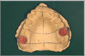
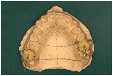
Once the stone sets, retrieve the cast and mark it for MSE adaptation (Figure 1).
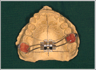
Adapt the appliance and guiding arms across the bands on the cast (Figure 2).
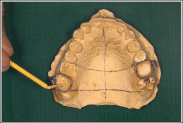
Remove the modeling wax from the bands and apply a thin layer of petroleum jelly or a separating medium to the inside surface of the bands and cast with an applicator tip (Figure 3).
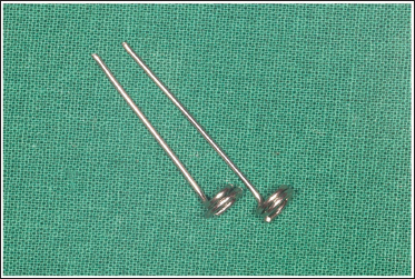
Take a 0.9-mm wire and fabricate two metal jigs as shown in the figure. The jig should have a coil with a diameter of at least 4 mm at one end and a straight extension from its center that is long enough to have a firm grip around it (Figure 4).
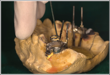
Place the jigs in the center of the band and pour a thin mix of dental stone into it. This step is important as it supports the bands throughout the fabrication process. Replacing the wax with stone avoids the chance of contamination during the soldering process, which can incorporate impurities into the solder joint and cause failure (Figure 5).
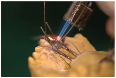
Adapt the MSE appliance and solder it (Figure 6).
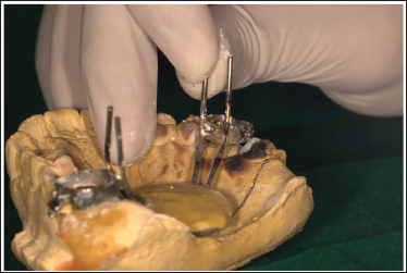
Once soldering is complete, hold the metal jig and pull it away. It will take out the 2nd increment of the stone along with it (Figure 7).
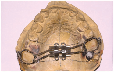
The MSE appliance can now be easily removed from the cast without any excessive force, thus preventing any distortion of the appliance (Figure 8).
Trim and polish the appliance (Figure 9).
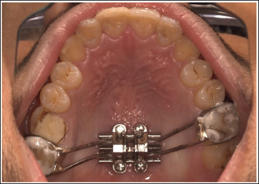
It can now be accurately transferred to the patient’s mouth, and the expansion can be started (Figure 10).
Markings for MSE Adaptation.
MSE Adapted with Adequate Clearance.
Modeling Wax Removed and Petroleum Jelly Applied.
Metal Jig.
Metal Jigs Centered Within the Bands and Dental Stone is Poured.
Soldering of the Guiding Arms to the Bands.
Metal Jigs Pulled Out.
Easy Retrieval of the MSE.
Trim and Polish the Appliance.
MSE Accurately Transferred to the Patients Mouth.
Conclusion
The above method can be employed to ensure a hassle-free and predictable approach in fabricating and transferring the MSE appliance from the lab to the patient’s mouth.
Footnotes
Acknowledgments
The author would like to extend a deep sense of gratitude to Dr. Won Moon, without whose inventions and contributions this article would not have been possible. The author would also like to thank Dr. Abhishek Pethe for helping with the photographs used in this article.
Declaration of Conflicting Interests
The author declared no potential conflicts of interest with respect to the research, authorship, and/or publication of this article.
Ethical Approval and Informed Consent
No ethical approval and patient consent were needed in the undertaking and making of the following article.
Funding
The author received no financial support for the research, authorship, and/or publication of this article.