
Abstract
Introduction:
The primary concern in the placement of ramal bone screws is the blind nature of the procedure, as there is a thick, mobile layer of soft tissue over the bone; also, the ramus is not a uniplanar structure but is swerving like a propeller blade. The purpose of this study was to evaluate the possibility of establishing clinical guidelines based on visible dental and soft-tissue landmarks for safe, reliable, and accurate insertion of ramal bone screws.
Aims and Objectives:
Our primary objective was to evaluate the angle formed between the appropriate direction of ramal-implant placement and the line tangential to the buccal surfaces of the first and second permanent molars. Our secondary objective was to evaluate the average distance of the neurovascular bundle from the tip of the bone screw.
Materials and Methods:
We obtained 80 cone beam computed tomography (CBCT) samples, marked reference lines and points on selected axial and coronal sections, and evaluated the following parameters using the software’s linear- and angular-measurement device: the angle between the appropriate direction of ramal bone screw placement and the line tangential to the buccal surfaces of the first and second permanent molars; and the proximity of the bone screw to the neurovascular bundle.
Results:
The angle between the constructed line of insertion and the occlusal line, as evaluated from our study, was 19.04 (SD ± 6.89) degrees. The proximity of the neurovascular bundle from the screw is 7.1773 (SD ± 1.73988) mm.
Conclusion:
We can conclude that ramal bone screws can be placed with a comfortable margin of safety.
Introduction
Mini-implants and bone screws offer innovative possibilities for utilizing anchorage from various sites. This makes the orthodontic tooth movement easy, quick, and with minimal or no side effects on adjacent teeth.
Uprighting a horizontally/mesioangular impacted molar requires both occlusal and distal components of force to unlock and upright the impacted lower molars. With conventional sources of anchorage, this movement is complicated and is not possible without a reciprocal effect on remaining dental units. With a ramal bone screw, the occlusal and distal eruptive movement of the third molar is an easy and comfortable procedure. 1 Even in other clinical situations where interdental, buccal shelf, or retromolar sites for insertion of temporary anchorage devices (TADs) may not be used for some reasons, the ramus offers yet another avenue for inserting and using skeletal anchorage.
Adding to this, there are vital neurovascular structures in and around the site of insertion. Thus, operators have hesitation in using this very beneficial modality of treatment to solve difficult situations. A clinical guideline, based on visible anatomic structures, is a practical directive in such circumstances where the thick soft tissue and twisted anatomy of the ramus make it tricky to estimate the direction of insertion.
The main concern in the placement of ramal screws is the blind nature of the procedure, as the soft-tissue thickness over the bone is very high and the ramus is not a uniplanar structure but is swerving like a propeller blade. The purpose of this study is to evaluate the possibility of establishing clinical guidelines based on visible dental and soft-tissue landmarks for safe, reliable, accurate, and precise insertion of ramal screws.
Design of a Ramal Bone Screw
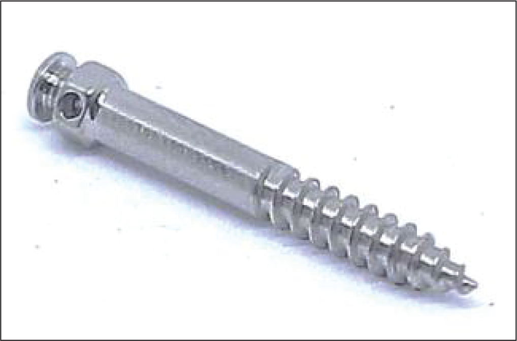
The thickness of the soft tissue traversed by a ramal bone screw is more compared to that of a buccal shelf screw 1 before the screw engages the dense cortical bone. Hence, a bone screw with an extended collar (Figure 1) is indicated.
Ramal Screw (FavAnchorTM SAS, 2 mm × 14 mm, India).
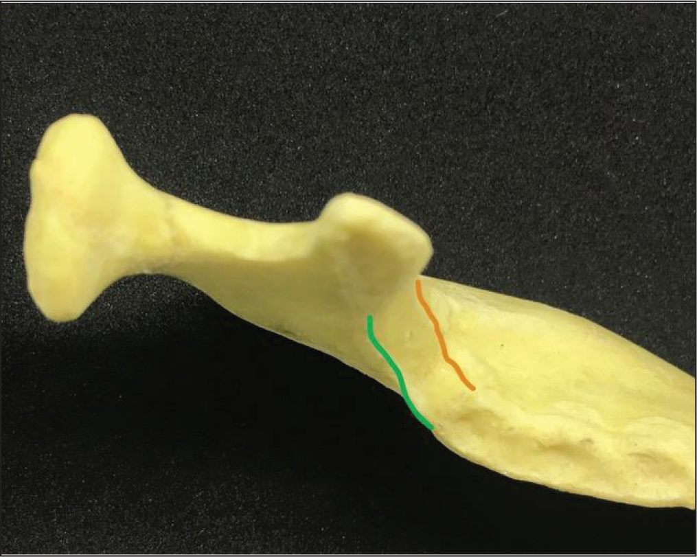
We can easily palpate and locate the external oblique ridge of the ramus intraorally, medial to which is the retromolar fossa, followed by the internal oblique ridge. The area about 5 to 8 mm above the occlusal plane, lying midway between the internal- and external-oblique ridges of the ascending ramus (Figure 2), is considered as an optimum site for placement of ramal screws without causing occlusal interference. 2
Area Between Internal Oblique Ridge (Green) and External Oblique Ridge (Orange).
Implants of smaller diameter (<2 mm), made of softer materials like titanium/titanium alloy, impose a substantial risk of fracture 3 through a self-drilling technique used in their insertion. Increasing the length of the screw should be avoided, as this would make it more susceptible to flexural stress. Thus, the use of a stainless-steel self-drilling bone screw of 2 mm diameter is recommended for this site.
Adequate oral hygiene measures are vital for the success of ramal screws; hence, oral hygiene instructions should be given and stressed upon while monitoring the soft-tissue condition at every appointment.
Ramal screws allow simple and efficient uprighting of impacted lower molars and address the mechanics in a better way, as they aid a more posterosuperior direction of traction. Thus, use of ramal screws for uprighting and distalizing mandibular molars is an efficient and convenient method.
Aims and Objectives
Primary Objective: To evaluate the angle formed between the appropriate direction of ramal-implant placement and the line tangential to the buccal surfaces of the first and second permanent molars.
Secondary Objective: To evaluate the average distance of the neurovascular bundle from the tip of the bone screw.
Need for the Study
We can use the average value of this angle as a guide for the optimum direction of insertion. The range of standard deviation would also indicate the safety margin in case of anatomic variations.
Injury to the neurovascular bundle of the inferior alveolar canal is one of the biggest fears in the operator’s mind. Thus, evaluating the average distance of the nerve bundle would help us in determining a safety margin considering the depth of insertion.
Materials and Methods
Materials
Cone beam computed tomography (CBCT) scans (80 subjects)
Romexis Viewer[Planmeca (Ver. 4.4.1.R), Helsinki, Finland]
Method
Measurements were made on CBCT scans, collected from the archives, without disclosing their identity. A total of 80 samples (40 males, 40 females; mean age: 29.56 years) were obtained for evaluation. Subjects were selected randomly, with a full complement of teeth and devoid of any craniofacial anomalies or systemic diseases. We used Romexis Viewer [Planmeca (Ver. 4.4.1.R)] for the image analysis. On the selected axial and coronal sections, reference lines and points were marked as described below and the aforementioned values were obtained.
The following parameters were evaluated using the software’s inbuilt linear- and angular-measurement tools: The angle between the ramal implant line and a line passing tangentially to the buccal surface of the mandibular first and second permanent molars was evaluated. Nerve Proximity: It is advised to place ramal implants at a level of 5 to 8 mm above the occlusal level.
10
Hence, we decided to evaluate this at 2 levels, at 4 mm and 8 mm above the occlusal plane.
The ‘N-Angle’
On the selected axial section, reference lines were established. This was done per the following steps:
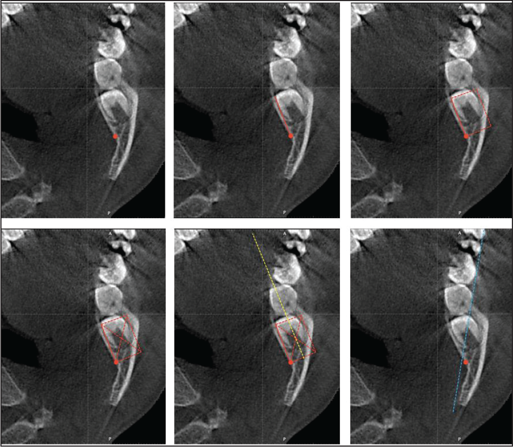
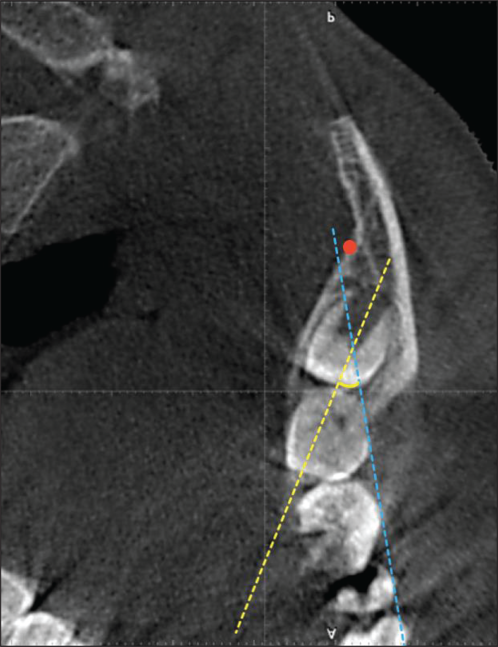
(a) Locate the inferior alveolar nerve; (b) construct a line joining the lingual border of the ramus to the inferior alveolar nerve; (c) construct a rectangle; (d) draw diagonals; (e) draw a line (yellow) passing through the intersection of the diagonals; (f) construct a line (blue) tangential to the buccal cusps of the first and second permanent molars.
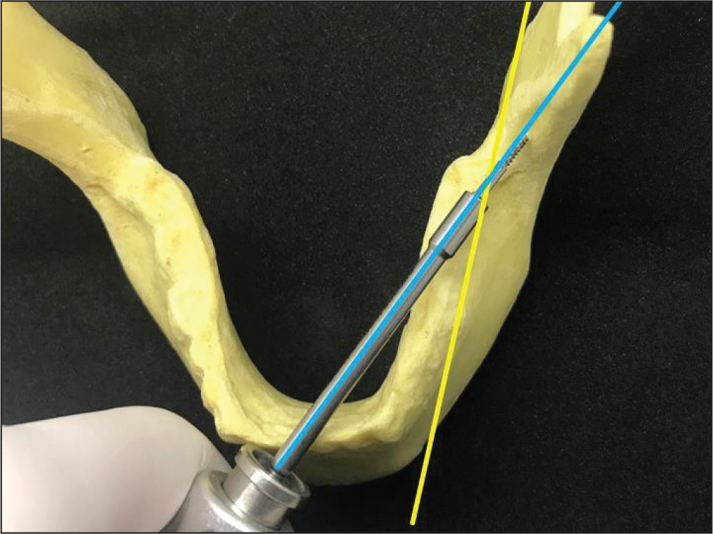
Angulation of the Implant Driver (FavAnchorTM SAS, India).
N-Angle.
Locate the inferior alveolar neurovascular bundle (Figure 3a).
Construct a line connecting the neurovascular bundle and the most antero-lingual point on the mandibular ramus (Figure 3b).
Construct a line parallel to the earlier-mentioned line, and draw 2 perpendicular lines to them, enclosing the widest part of the body of the ramus, thus forming a rectangle (Figure 3c).
Draw the 2 diagonals of the rectangle and mark a point at their intersection (Figure 3d).
Draw a line passing through this point and parallel to 2 sides of the rectangle. This indicates the centre of the ramus, and thus the most suitable direction of insertion for ramal implants (Figure 3e).
Construct a second reference line tangential to the buccal cusp of the permanent mandibular first and second molars (Figure 3f).
Measure the antero-lingual angular measurements between these 2 lines using the software’s inbuilt angular-measurement tool. In a clinical scenario, this is the angle formed between the line tangential to the buccal surface of the first and second permanent molars and the ramal screw loaded on the implant driver (Figure 4) as it is being inserted in the ramus. This angle was named by us as the ‘N-Angle’ (Figure 5).
For evaluation of the secondary objective, digitally trace the inferior alveolar neurovascular bundle on a selected coronal slice. Place bone screws (2 mm × 14 mm) virtually in the ramal region at an insertion depth of 5 mm and assess their vicinity to the neurovascular bundle. Do this at 2 levels, at 4 mm and 8 mm from the occlusal plane.
Results
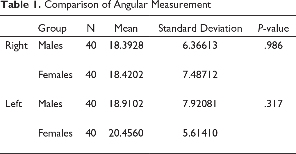
Software (SPSS, version 17.0, Chicago, IL) were used for all statistical analyses. The right and left measurements (Table 1) of the earlier-mentioned angle were not significantly different (P < .05). They were therefore pooled (Table 2).
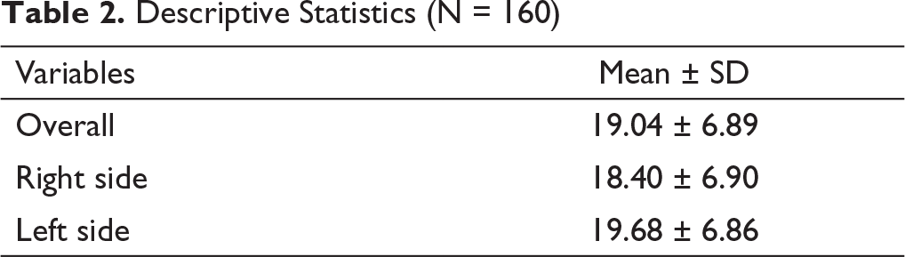
The average angle between the optimum site for placement of ramal implants and the occlusal line passing through the permanent mandibular first and second molars was 19.04 degrees (SD ± 6.89).
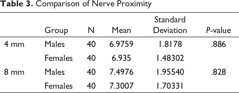
There was no significant difference in the mean value of nerve proximity with the constructed line of insertion (Table 3) between males and females. The mean nerve proximity on the right side was 0.15 mm more than the mean value on the left side.
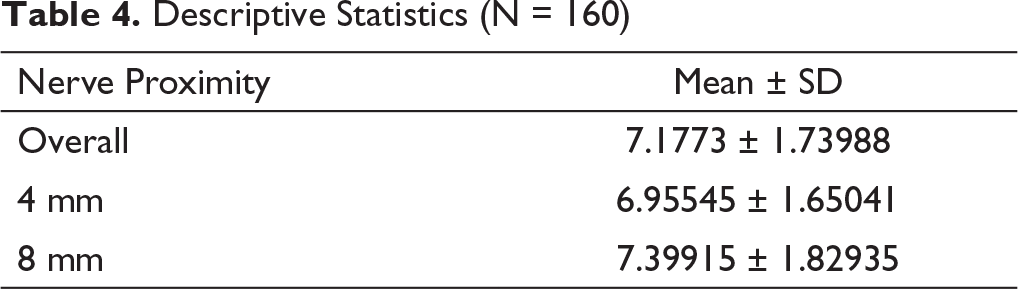
The distance from the implant tip to the inferior alveolar neurovascular bundle, at the endo-osseous insertion depth of 5 mm, was the least (Table 4) at a height of 4 mm from the occlusal plane, 6.95545 (SD ± 1.65041) mm, and the most at 8 mm, 7.39915 (SD ± 1.82935) mm. Both these values signify a clinically safe margin of placement from the standpoint of iatrogenic damage to the inferior alveolar neurovascular bundle.
Statistical Analysis
Comparison of Angular Measurement
Descriptive Statistics (N = 160)
Comparison of Nerve Proximity
Descriptive Statistics (N = 160)
Discussion
The most common impacted tooth is the third molar, followed by the maxillary canine and mandibular second molars. It is usually desirable to upright horizontally impacted mandibular second molars. It may also be valuable to upright impacted third molars if the adjacent first or second molars are decayed or compromised. Retrieving horizontally impacted mandibular molars can be difficult, and they may not always respond to routine orthodontic treatment.
Various methods to recover deeply impacted molars reported in the literature involve the use of removable appliances that require patient cooperation, along with/without surgical exposure of the impacted tooth, and may also involve removing part of the alveolar bone.4- 10 Also, both direct and indirect methods using miniscrews can be used as an alternative treatment to mandibular molar uprighting. 11
An effective treatment strategy involves the use of skeletal anchorage devices at biomechanically favorable extra-alveolar sites. To address this issue, anchorage is needed from the anterior ramal region of the mandible so as to provide a more superior and posterior direction of traction, along the plane of the impaction. Lin 12 determined that the most reliable and efficient approach was to surgically expose the deeply impacted molars and upright them using a ramal bone screw.
In spite of the numerous biomechanical advantages of ramal bone screws, there are numerous concerns about the placement site, namely highly mobile alveolar mucosa, difficult oral-hygiene maintenance, soft-tissue hyperplasia, thick layer of soft tissue, and an underlying layer of active bone. Thus, a long-collared 2 mm x 14 mm stainless-steel screw can be considered as the best fit for the anatomical features of the anterior ramus region.
Soft-tissue hyperplasia or inflammation in the anterior ramus area can be challenging and may lead to screw failure. However, a preliminary study found a failure rate of only 5% for ramus screws, which is lower than for mandibular buccal-shelf screws (7.2%). 13
The anatomic structure near the ramus presenting the most serious risk for complications is the neurovascular bundle in the inferior alveolar (mandibular) canal. From the perspective of iatrogenic damage to the inferior alveolar neurovascular, the distance from the implant tip to the inferior alveolar neurovascular bundle signifies a clinically safe margin of placement.
Also, the approach of uprighting horizontally impacted third molars before extraction may be a wise measure to avoid damaging the second molar and its periodontium and the inferior alveolar nerve during a surgical extraction procedure, even if no other orthodontic treatment is done.
The risk of fracture is considerably higher for smaller-diameter (<2 mm) screws of brittle make (titanium or titanium alloy) self-drilled into dense cortical bone. It can be considerably reduced by using a screw of diameter at least 2 mm made using a sturdy material like stainless steel. Increasing the length of the screw to 14 mm makes it more susceptible to flexural fracture, but considering its use in the ramal area and the need for excess soft-tissue penetration, it is more favorable than screws of 12 mm.
Insertion of ramal bone screws is a predictable method with a lower failure rate as compared to buccal shelf bone screws (7.2%), as well as inter-radicular miniscrews in the maxilla (12%) and mandible (19.5%).13- 15 Thus, ramal bone screws can be effectively used to align deeply impacted, horizontal mandibular molars.
Conclusion
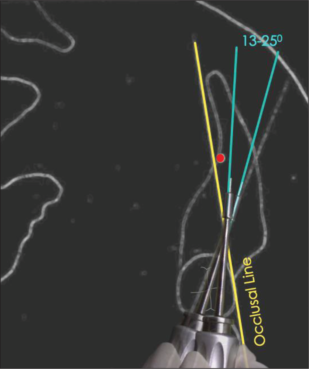
The angle between the constructed line of insertion and the occlusal line as evaluated from our study was 19.04 (SD ±6.89) degrees. This wide variation can be a result of individual anatomic variation, as seen in our study. This indicates that placement of ramal implants should be in the range of 13 to 25 degrees to the occlusal line (Figure 6). The distance of the neurovascular bundle from the screw is 7.1773 (SD ± 1.73988) mm, which implies that this mode of skeletal anchorage can be used with a comfortable margin of safety.
Schematic Representation of “N-Angle.”
Footnotes
Statement of Informed Consent and Ethical Approval
Necessary ethical clearances and informed consent was received and obtained respectively before initiating the study from all participants.
Declaration of Conflicting Interests
Funding
The authors received no financial support for the research, authorship, and/or publication of this article.