
Abstract
Implant placement has always been a difficult task to accomplish. Several designs and methods have been proposed for precise implant placement in order to gain absolute anchorage in orthodontics. Implant placement grids and templates have always been used for placing mini implants since 1980. The aim of this article is to provide a simple and efficient method to construct an orthodontic Mini Implant Punch (MIP) made up of Australian 0.018″ stainless steel wire with easy wire bending.
Introduction
Anchorage conservation in totality has been a common problem for all orthodontists. Conventional means of supporting anchorage rely on either intraoral sites or extraoral means. Both of these have their own limitations. The extraoral forces are dependent on the patient’s compliance and cannot be used 24 hours a day to resist the continuous teeth-moving forces. Anchor loss is the perennial problem in conventional intraoral methods, although patient compliance is not an issue. Studies of Prof Branemark, a pioneer in osseointegrated implants, have created a new horizon in the field of dentistry. Micro implants were introduced for their use in orthodontics.
These orthodontic implants made up of titanium have changed the traditional concepts of anchorage. They are now widely used as “Absolute Anchorage,” which is independent of dental units for anchorage. 1 However, clinicians may face certain complications when treating cases with implant anchorage, such as mobility of micro implants, oro-antral communication, peri-implantitis, proximity to tooth root, undesirable tooth movement, and fracture of micro implant. The vicinity of micro implants to the adjacent tooth root is a major risk factor for implant failure. This is more common in the lower jaw, suggesting that micro implant placement technique needs to be accurate to avoid root proximity and loosening of implants. A micro implant, when touching the root, may cause root resorption, loss of vitality, osteosclerosis, and dentoalveolar ankylosis. Hence, accurate placement of an implant is necessary for its success. “Implant guides” help in the precise placement of miniscrews and are therefore necessary for accurately placing implants, thereby avoiding such complications.2-4
Material and Method of Fabrication of “Mini Implant Punch”
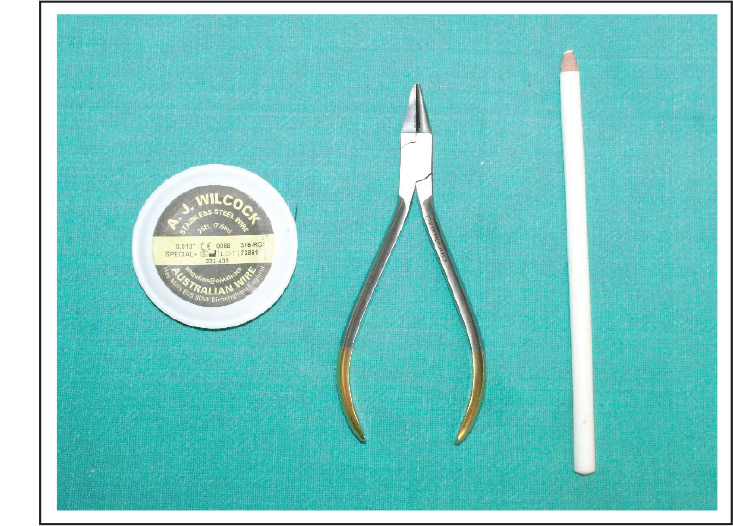
Armamentarium (Figure 1)
0.018″ AJ Wilcock stainless steel wire
Bird beak plier
Glass marking pencil
Method
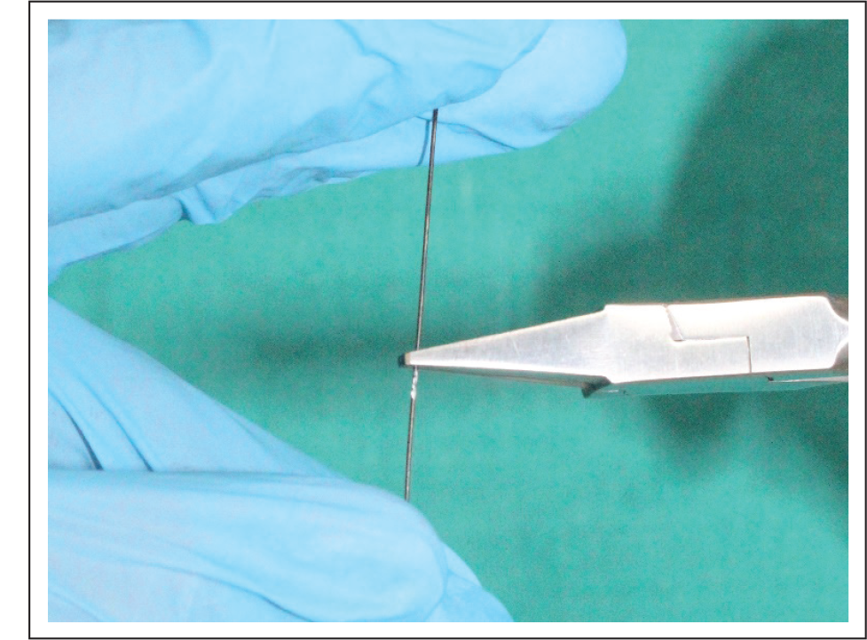
A 0.018″ AJ Wilcock stainless steel wire made straight and center of the wire was marked with a glass marking pencil (Figure 2a).
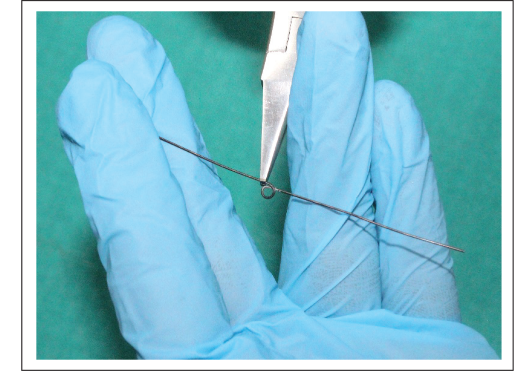
At the marking point, a helix of diameter 3 mm was incorporated (Figure 2b).
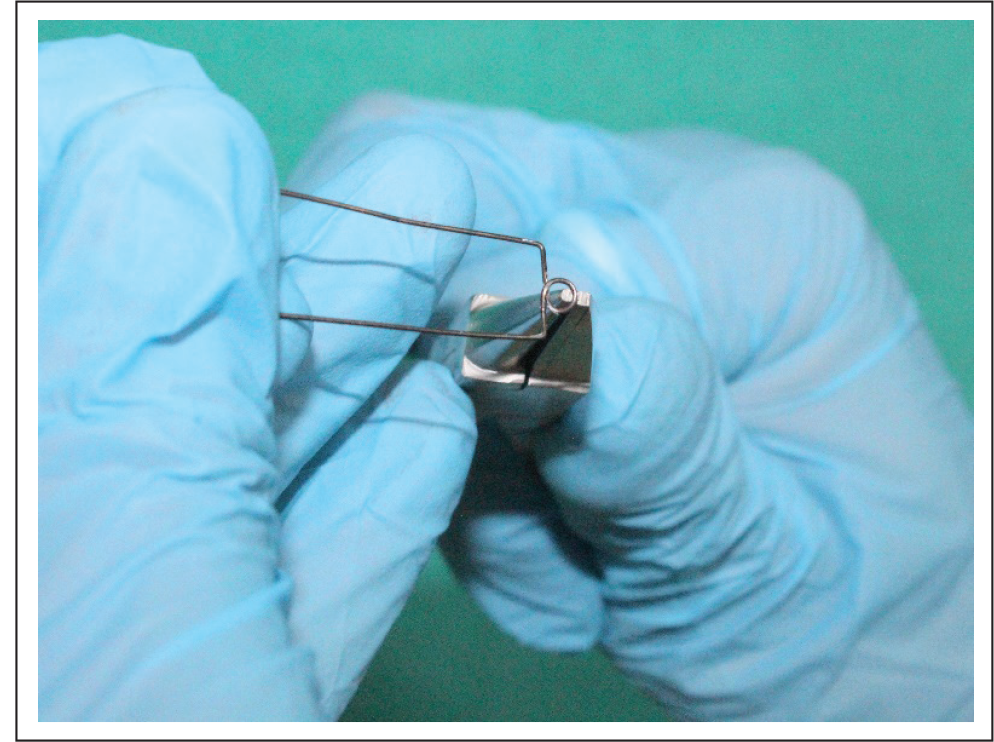
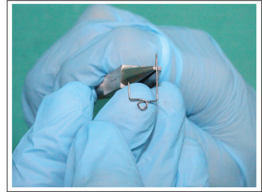
Then, points were marked 4 mm on either side of the helix and bent 90 degrees (Figure 2c).
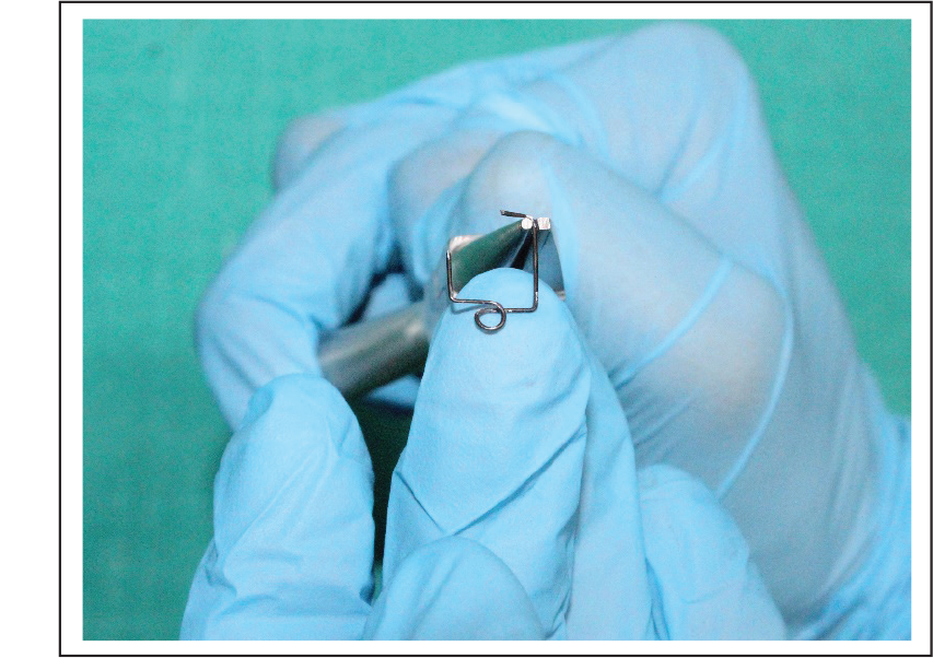
Buccal arm of length 7–8 mm long and lingual arm of length 4–5 mm were taken (Figure 2d).
Buccal arm was again bent 90 degrees for 3 mm (Figure 2e).
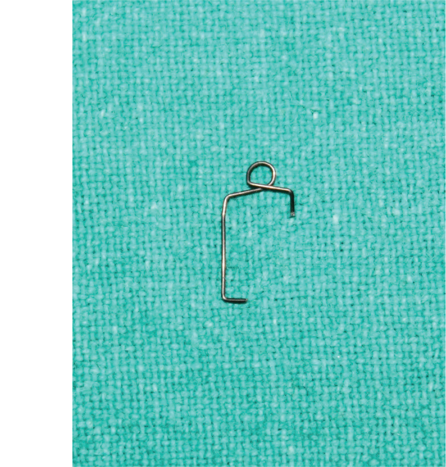
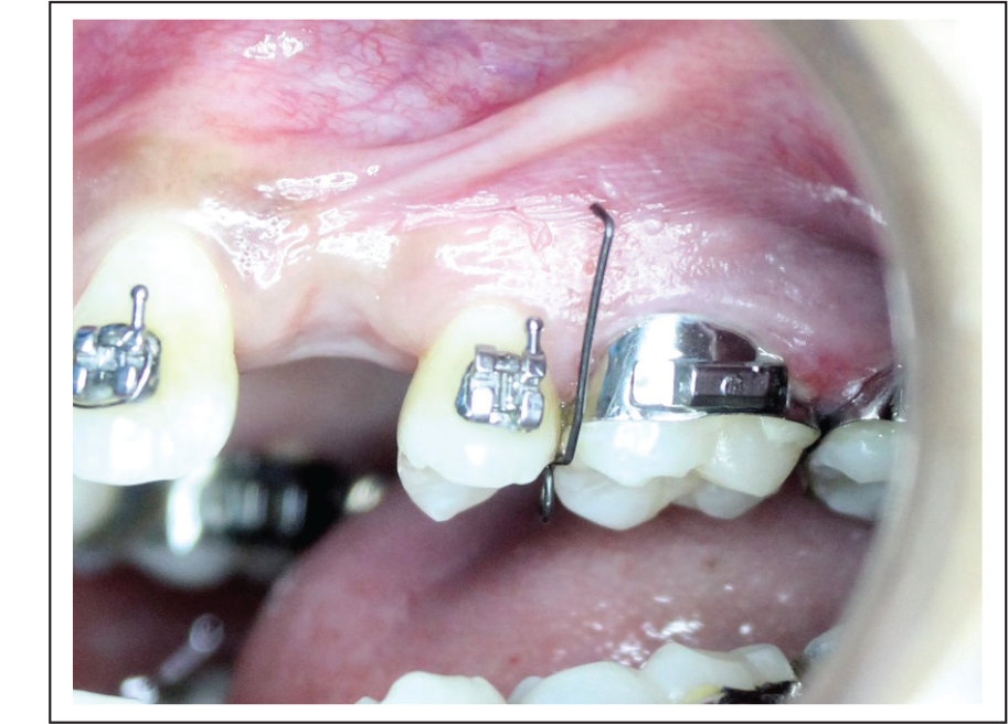
Placement
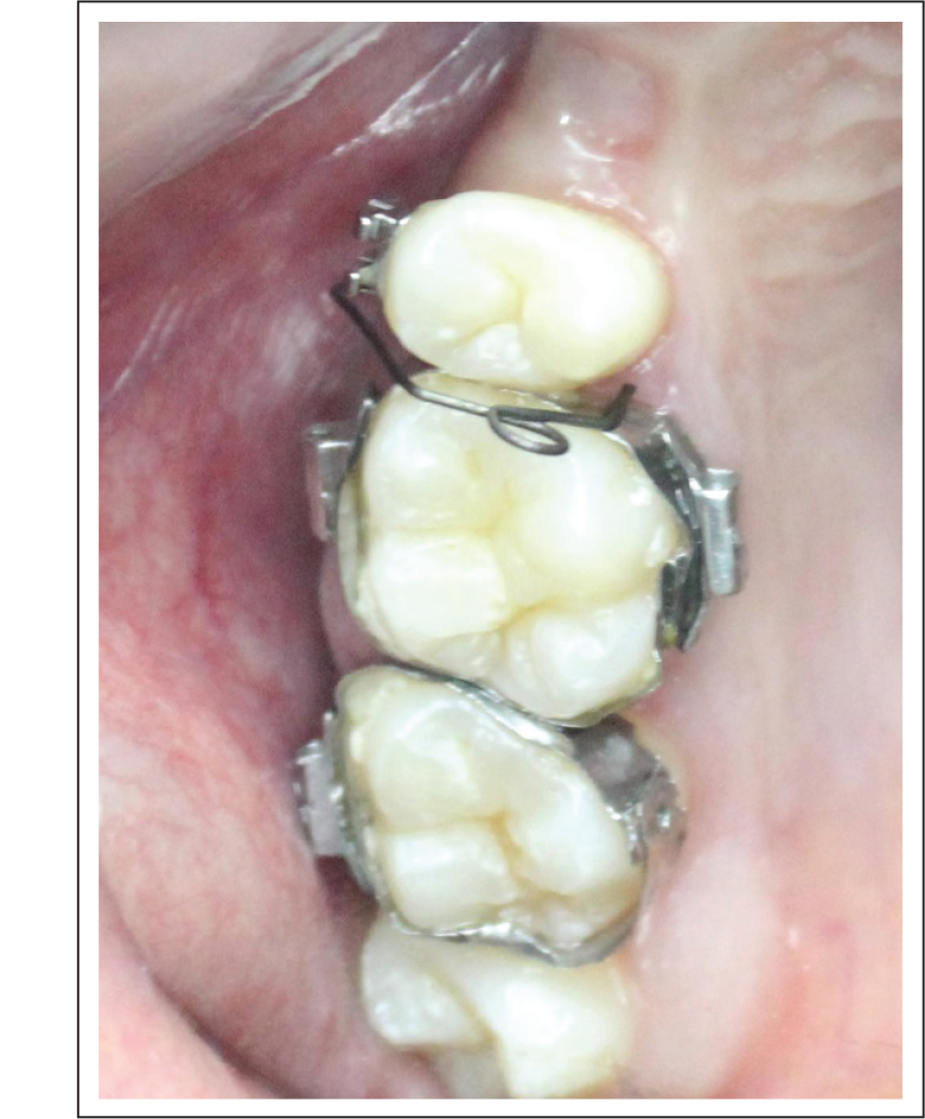
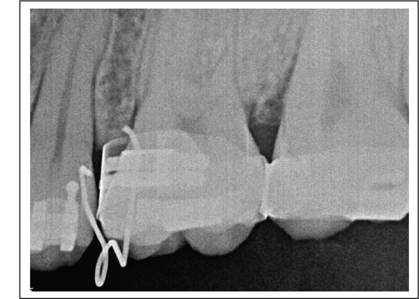
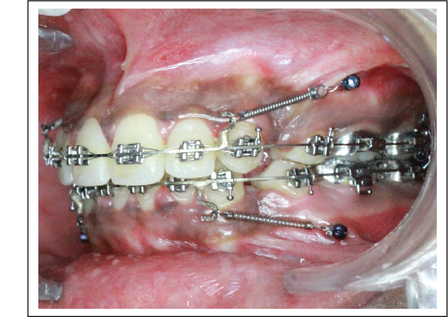
The fabricated MIP (Figure 3) was placed between the second premolar and first permanent molar (P2M1), with the buccal arm resting on the buccal attached gingiva (Figure 4), helix lying occlusaly (Figure 5), and the lingual arm resting interdentally on the palatal side. After placement, the buccal arm was punched against the buccal attached gingiva, and the bleeding point was obtained (Figure 6). Intraoral periapical (IOPA)/radiovisiograph (RVG) was taken to know the height of the bone for precise placement of the miniscrew (Figure 7). Then, the implant was placed on the bleeding point (Figure 8).
Sterilization Protocol
Mini Implant Punch Preparation
MIP is autoclavable.
We recommend that MIP- and temporary anchorage device (TAD)-related instruments be sterilized separately in either a cassette sealed in a self-sealing sterilization pouch, or individually, in a self-sealing sterilization pouch.
Do not sterilize MIP devices unwrapped.
Sterilization and Disinfection of Patient
The patient is instructed to rinse with a chlorhexidine solution.
Wipe the patient’s mouth area with an oral disinfectant. Hypochlorous acid (30 ppm) or chlorhexidine may also be used.
Place the sterile drape over the patient’s face to isolate the field.
Wipe the recipient area with an oral disinfectant.
Armamentarium Required for Fabrication of Mini Implant Punch.
A 0.018″ A. J. Wilcock Stainless Steel Wire Made Straight and Center of the Wire is Marked with a Glass Marking Pencil.
At the Marking Point, a Helix of Diameter 3 mm Is Incorporated.
Points are Marked 4 mm on Either Side of Helix and Bent 90 degrees.
Buccal Arm of Length 7–8 mm and Lingual Arm of Length 4–5 mm are Taken.
Buccal Arm is Again Bent 90 Degrees for 3 mm.
Mini Implant Punch Fabricated.
Buccal Arm Resting on Buccal Attached Gingiva.
Helix Lying Occlusally.
Bleeding Point Punched.
RVG is Taken to Know the Height of the Bone for Precise Placement of Miniscrew.
Placement of Miniscrew Implant.
Advantages
Chairside construction;
Can be fabricated for any site;
Minimum armamentarium required;
Easy and simple wire bending;
IOPA/RVG can be easily taken after guide placement;
No need to remove base archwire for mini-punch placement; and
Comfortable for the patient.
Conclusion
The “mini implant punch” (MIP) made up of Australian 0.018″ stainless steel wire, is a simple and efficient method to guide implant placement with easy wire bending.
Statement of Informed Consent:
Informed consent was not sought for the present study because no identifiable images were used.