
Abstract
Pulse injection hydraulic fracturing (HF) can release high-energy peak pressure in a split-second, forming a complex hydraulic fracture network in shale reservoirs. However, the initiation and propagation of multiple fractures in the horizontal well of shale reservoirs under pulse injection HF have been inadequately studied. Hence, in this study, a HF model coupling the fracturing fluid flow along the fracture and the rock deformation was adopted, and the effect of the pulsed injection method on multistage HF of horizontal wells was determined. The results show that the pulsed injection HF can improve the fracturing effect of horizontal wells. However, no matter how the injection displacement and pulse frequency change, the propagation length of cracks at both ends seriously disturbed by stress almost remains unchanged. When the dominant fracture is temporarily shielded, the fluid pressure of the non-dominant fractures at both ends disturbed by stress compression increases, and the non-dominant fractures can be further expanded. Thus, a new composite multistaged HF scheme suitable for horizontal wells with pulse-temporary shielding in shale reservoirs was proposed. The method presented here can be adopted to optimize the fracture growth regime and provide a scientific basis for the fracturing operation of the horizontal well in shale reservoirs.
Keywords
Introduction
Multistaged hydraulic fracturing (HF) of horizontal wells is an important technology for oil and gas reservoir stimulation and completion operation (Roussel and Sharma, 2010). Currently, it has been widely used in the stimulation of low-permeability oil and gas reservoirs with great success (Sesetty and Ghassemi, 2015; Soliman et al., 2008). However, the perforation opening efficiency of each fracturing stage was found to be lower by post-fracture evaluation, especially in the first fracturing, where the number of fracturing clusters in a single was typically below 60% (Cheng et al., 2017). Therefore, achieving the efficient initiation and uniform propagation of each perforation cluster in a single stage as far as possible has become a key challenge in shale gas development.
A large number of field experiences and experimental studies have shown that artificially injecting the output displacement and pressure of the surface fracturing pump group in a pulse injection manner can significantly improve the effect of HF (Liu et al., 2022; Yoon et al., 2015; Hofmann et al., 2018). Thus, a series of important works have been carried out in the application of pulse injection in shale gas. Researchers have found that the pulse injection HF can release high-energy peak pressure in a very short time, and achieve the same effect as explosive HF (Li et al., 2014). To further capture the effect of pulse injection HF on reservoir permeability, pulse injection HF experiments under the experimental conditions were conducted (Diaz et al., 2020; Li et al., 2020). The research revealed that the production rate of the reservoir was significantly increased, and the permeability has increased by two orders of magnitude when the pulse injection method was subjected (Chang et al., 2017). The application in shale reservoir also proves this conclusion, that is, pulse injection HF has the advantages of constant injection and explosive HF in shale reservoirs (Safari et al., 2015; Tariq et al., 2019). Adjusting the parameters of pulse injection HF (injection displacement and pulse frequency) to adapt to the reservoir, it is possible to produce multi-directional propagation fractures and improve the effect of HF greatly (Diaz et al., 2020).
Adjusting the injection displacement and pulse frequency of the ground pump in a timely manner enables the pressure wave generated in the pumped fracturing fluid to instantly increase the energy at the “to-be-broken point,” which can promote the propagation of fractures (Zhai et al., 2015; Li et al., 2014). However, since the pulse injection HF has not been applied on a large scale, it remains to be verified whether the pulse injection HF is helpful for the formation of complex fracture networks (Zimmermann et al., 2015; Hou et al., 2021). Additionally, frequent injection pressure changes (caused by injection displacement and pulse frequency) may complicate the propagation process of multi-perforation clusters in horizontal wells. To the best of our knowledge, no study has shown the overall effect of key pulse injection HF parameters (injection displacement and pulse frequency) and their implication on the initiation and propagation of multi-cluster fractures in the horizontal well of shale reservoirs.
Hence, to evaluate the influence of pulse injection methods on the multi-fracture geometry and stress interaction in the multistage HF, an HF model coupling the fracturing fluid flow along the fracture and the rock deformation was adopted in this paper. Using the coupled method, the impact of pulse frequency and injection displacement on the initiation and propagation of multiple fractures was analyzed, and the application of pulse injection HF in horizontal wells was verified. On this foundation, considering the temporary shielding technology, a composite staged HF scheme suitable for horizontal wells with pulse-temporary shielding in shale reservoirs was further proposed. The results of this study provide a deep understanding of the pulsed injection HF and significant suggestions for the fracturing operation of the horizontal well in shale reservoirs.
Methods
Extended finite element method
Figure 1 shows the complementary thermal-hydraulic (TH) coupling and the fracture network mechanism, in which the variables are fully coupled. By coupling the three fields, the model can calculate the effect of the pressure wave induced by the pulse injection on the fracture initiation and propagation in each perforation cluster. Additionally, compared with other crack simulation methods based on the finite element method (FEM), the extended finite element method (XFEM) can simulate crack propagation in any direction according to the stress state at the crack tip without re-gridding. Furthermore, by extended the finite element primary functions, XFEM can also accurately describe the complex unknown field formed at the crack tip due to the pressure wave induced by the pulse injection. Hence, one can see that the mechanism and characteristics of pulse HF can be fully considered by the model, which can well simulate the initiation and expansion of hydraulic fractures under the pulse injection HF (Figure 1).
Fluid flow equation in the fractures: The fluid is assumed to be an incompressible Newtonian fluid (Camanho and Davila, 2002). According to the assumptions, the tangential flow in each fracture is controlled by the lubrication equation (Rahim and Holditch, 1993):
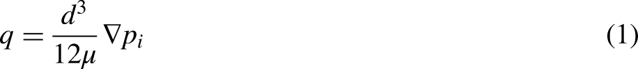

Complementary TH coupling and the fracture network mechanism.
where μ is the dynamic viscosity of fracturing water, Pa.s; d is the fracture opening, m; q is the tangential volume flow of fracturing water, m3/s; ▽pf is the fluid pressure gradient along the cohesive, Pa/m; qt and qd are the flow rates of fracturing water flowing into and out of the upper and lower surface of the cohesive elements, m3/s.
The normal flow of cohesive elements Substituting Equations (1) and (3) into Equation (2) results in the Reynolds lubrication equation (2) Coupled deformation equation of porous media: Considering that the rock is a porous medium, Biot constitutive model is used for simulation. The governing equation of porous media deformation is as follows: Balance equation: Constitutive equation: XFEM discretization of the variational form: To avoid remeshing in HF and simulate the singularity of fracture tips, a mesh-independent crack propagation method, XFEM, proposed by Belytschko and Moes, was adopted in this paper. Compared with other crack simulation methods based on FEM, XFEM has the following advantages: (1) The propagation of cracks in any direction can be simulated based on the stress state at the crack tip without re-gridding; (2) The definition of initial cracks (perforation clusters) is more convenient; (3) Regular grids can be used; (4) The singularity of the crack tip can be easily captured.
where the Pt and Pb are the pore pressure in the adjacent porous elastic material at the top and bottom of the cohesive elements, respectively, Pa; ct and cb are the corresponding leakoff coefficients, m3/(Pa.s); Pi is the fluid pressure acting on the fracture surface, Pa.
where B is the volume force; σ’ is the Biot equivalent stress tensor, defined as:
where C is the tangential modulus matrix; ε is the strain tensor.
XFEM can describe complex unknown fields (such as crack tip fields) more accurately by extended the finite element primary functions (Ma et al., 2017). The extended function can be selected based on the prior knowledge or analytical solution according to the category of the problem. For example, the step function can be selected as the extended function for the crack simulation problem, and the crack tip asymptotic function can be selected as the extended function for the singular field at the crack tip (Figure 2).
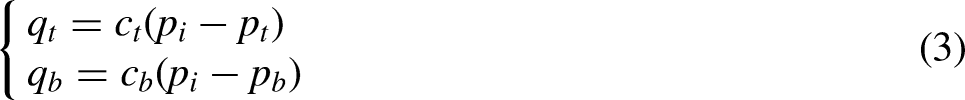


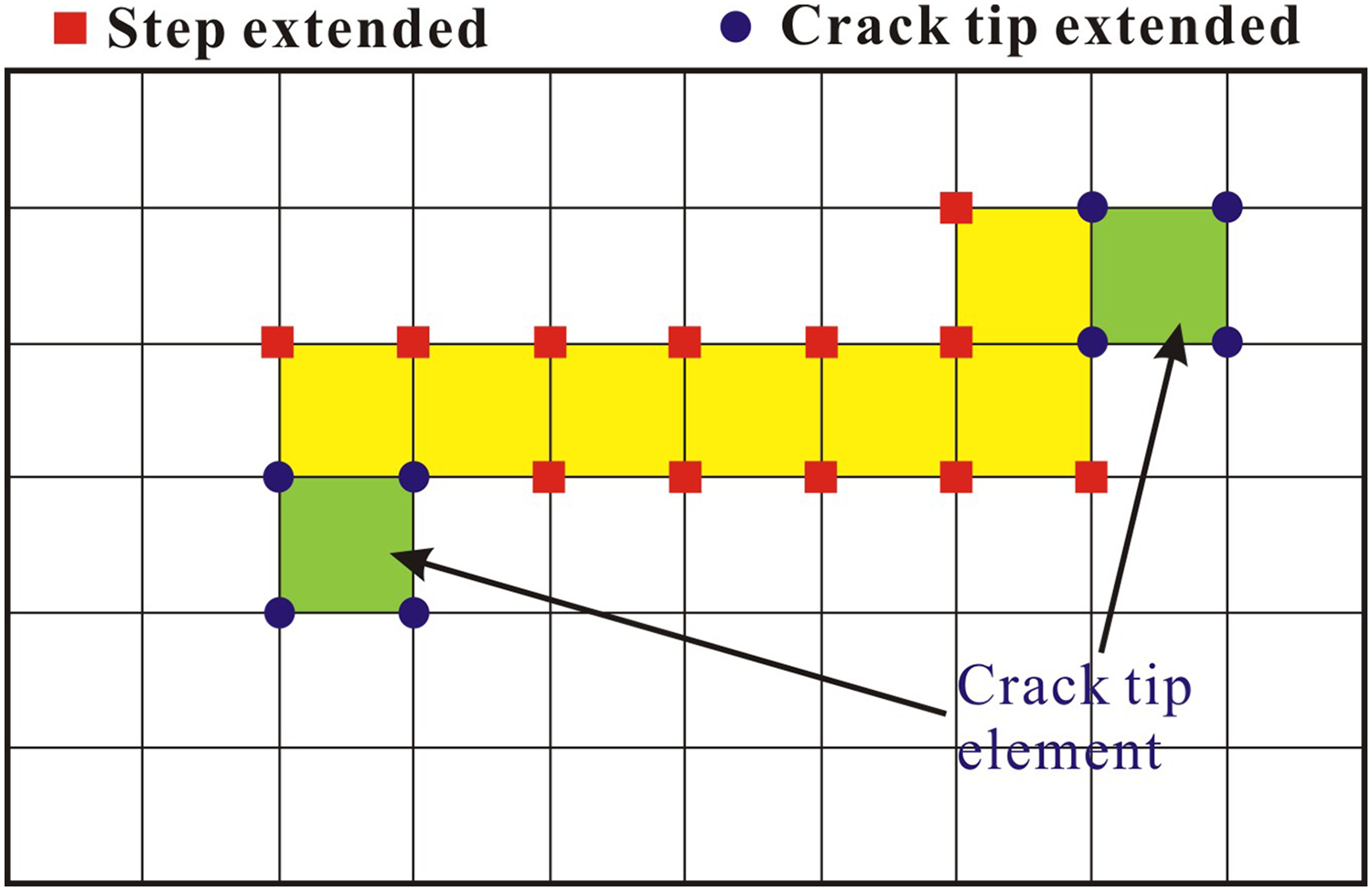
Diagram of crack tip extended and step extended of XFEM.
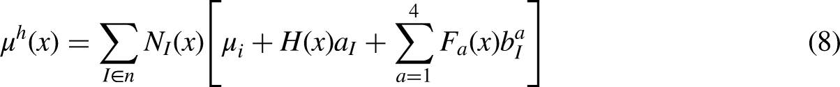
The displacement field of XFEM is discretized as follows (Shi et al., 2017):

Numerical models and procedure
Numerical models for multistage fracturing: Compared with the constant injection method, in a single fracture, the pressure wave generated by the pulse injection will increase the internal pressure in the fracture and make the fracture grow further, and in this simulation case, the two methods are well comparable. Thus, to evaluate the influence of pulse injection methods on the multi-fracture geometry and stress interaction in the multistage fracturing technology, a HF model coupling the fracturing fluid flow along the fracture and the rock deformation (XFEM) was developed (based on Abaqus software).
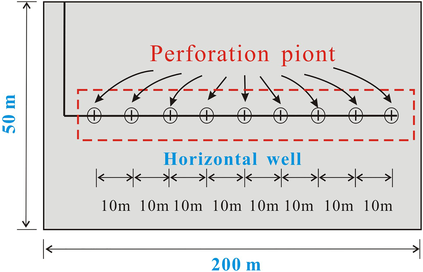
In the actual HF process of shale gas in southern Sichuan, the horizontal well usually contains multiple fracturing stages (12 fracturing stages), and each fracturing stage often contains multiple perforation clusters (8–10). Compared with the constant injection method, the pulse injection in the process of multistaged fracturing mainly promotes the uniform opening and balanced propagation of each perforation cluster in a single fracturing stage by generating pulse waves. Therefore, only one fracturing stage (including 9 perforation points) in the horizontal fracturing section was selected. Taking a single fracturing stage as an example, it can not only make the comparison more targeted, but also make the analysis of the opening and propagation of a single perforation cluster under pulse injection HF more intuitive.
Figure 3 shows the pulse injection HF model of a single fracturing stage in the horizontal well. The model is 200 m in length and 50 m in height. The horizontal fracturing stage of the horizontal well is 100 m, a perforation cluster is set as 10 m, and the initial length of the perforation cluster is 1 m.
Mechanical parameters and stress orientation: The numerical simulation study takes the shale gas horizontal well of Weiyuan-1 as an example. Based on the azimuth angle of drilling-induced fractures interpreted from formation microscanner image (FMI) logging, the principal in-situ stress directions in well Weiyuan-1 were determined. According to the azimuth probability range of tensile fractures in the FMI logging, the maximum horizontal principal stress azimuth at FORGE may be 25–30° east to north.
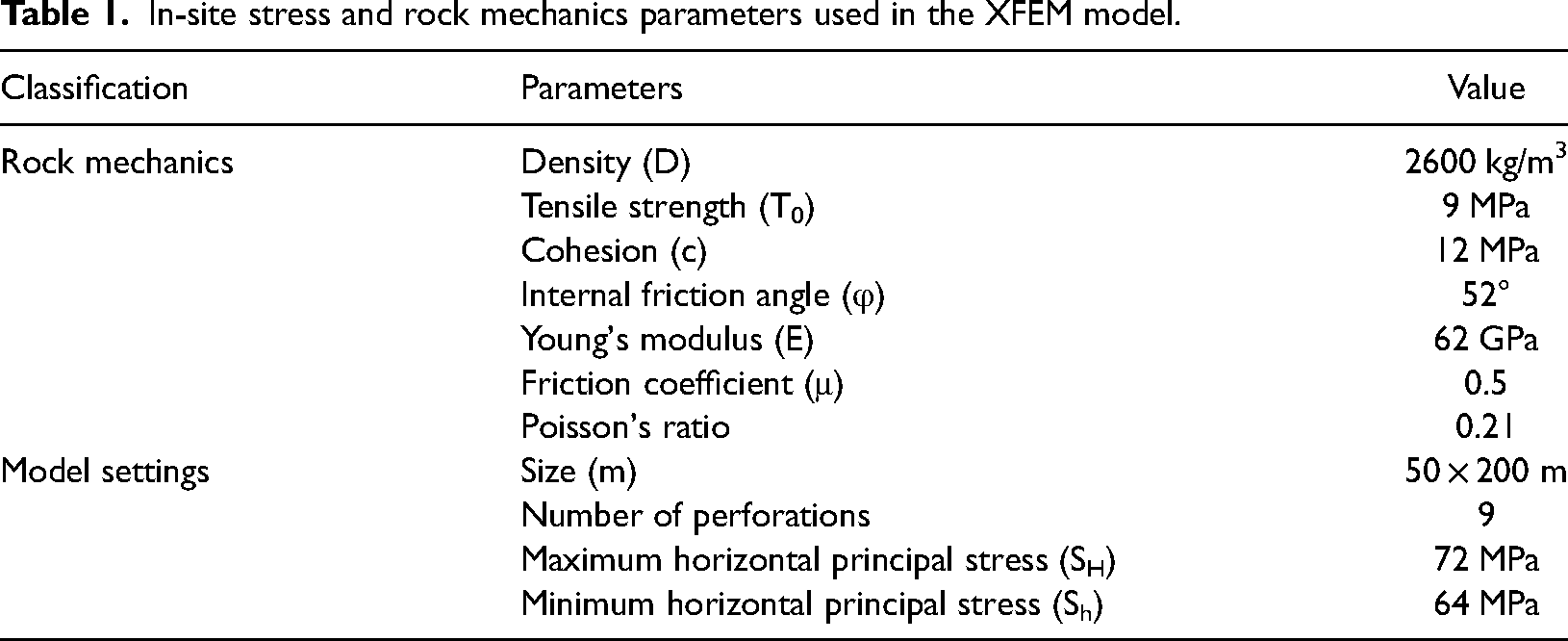
The density of the fracturing fluid was specified as 1000 kg/m3 and the dynamic viscosity as 0.002 Pa·s. The in-situ principal stresses of the model are set as Sh = 64 MPa, and SH = 72 MPa (Table 1).
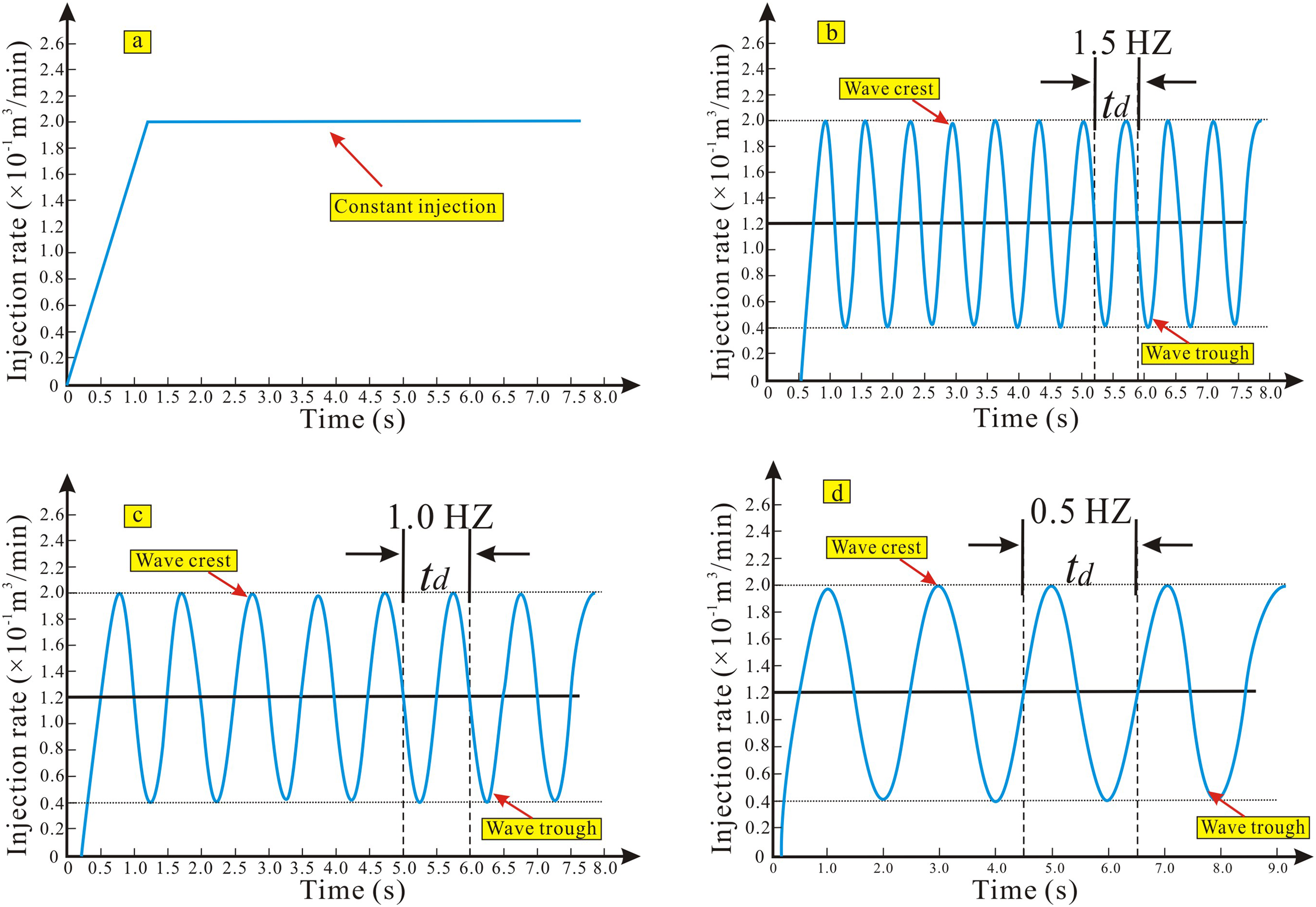
Injection methods: To capture the impact of pulse injection methods on the initiation and propagation of multiple fractures in the horizontal well, the constant injection and pulse injection HF were simulated and compared (Figure 4). Additionally, considering the overall effect of key pulse injection HF parameters (injection displacement and pulse frequency) and their implication on the initiation and propagation of multi-cluster fractures in the horizontal well of shale reservoirs, HF simulation under different injection displacement and pulse frequency were designed (Table 2). Figure 4 illustrates the injection schemes of three pulse frequencies (0.5 Hz, 1 Hz, 1.5 Hz) cases under the same injection displacement and in-situ stress.
To capture the impact of different pulse frequencies on the initiation and propagation of multi-cluster fractures in the horizontal well of shale reservoirs, three different pulse frequencies (0.5 Hz, 1.0 Hz, and 1.5 Hz) with the same injection displacement (2 m3/min) and total injection volume (200 m3) were designed. Besides, three groups of comparative schemes were set up to study the impact of injection displacement on fracture propagation. The injection displacement was set as 1, 2, and 3 m3/min. For comparability of injection schedules, pulse frequency was consistent with each other (Table 2).
Geometrical models of multistage pulse injection hydraulic fracturing.
The injection schemes of three pumping frequency (0 Hz, 0.5 Hz, 1.0 Hz, 1.5 Hz) cases.
In-site stress and rock mechanics parameters used in the XFEM model.
Scheme of pulse injection hydraulic fracturing for a horizontal well.
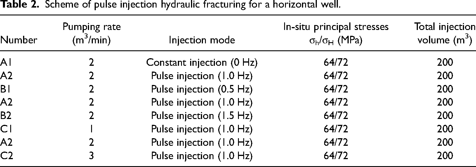
During HF, the initiation and propagation of perforation clusters in each fracturing stage are largely affected by the total injection volume. Therefore, to eliminate the influence of the injection volume on fracture initiation and propagation, the total injection volume of the model is consistent with each other.
Model calibration
In this section, the numerical model was compared and calibrated with actual engineering practice to verify its accuracy. To make the numerical model comparable with the actual engineering, the test conditions (temperature, in-situ stress), rock mechanical parameters and fluid injection method of the numerical model are consistent with the actual engineering.
The simulation results show that the injection pressure obtained by the numerical model is in good agreement with the measured pressure, and there are differences only at the peak injection pressure and the pump stop pressure. However, this difference is slight and the relative error maintains at a small value, which verifies the accuracy of the numerical model (Figure 5). The comparative analysis shows that the numerical model is scientific and effective, and it can be used to predict and evaluate the initiation and propagation of hydraulic fractures.
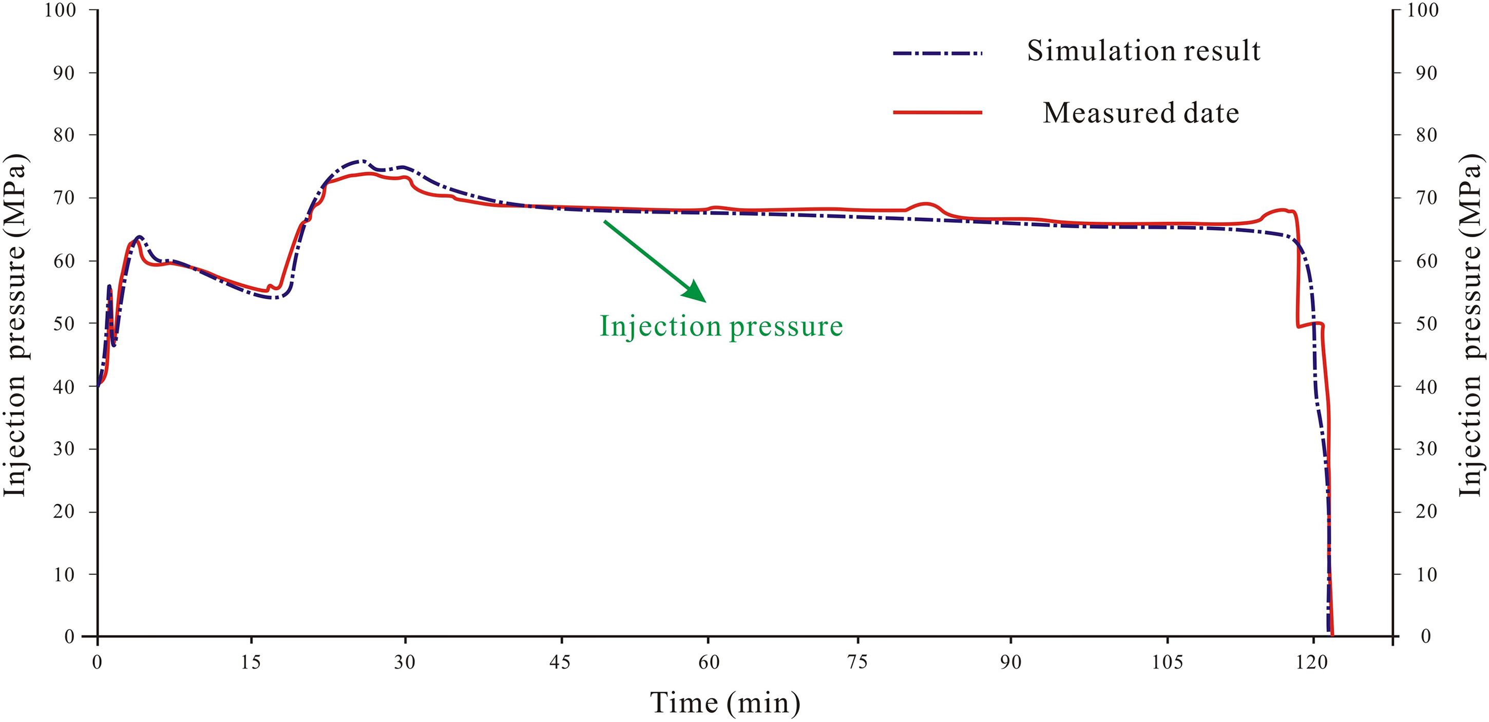
Comparison between measured injection pressure (Weiyuan-1 well) and simulation results.
Results and analyses
Multistage hydrofracturing of constant and pulse injection models
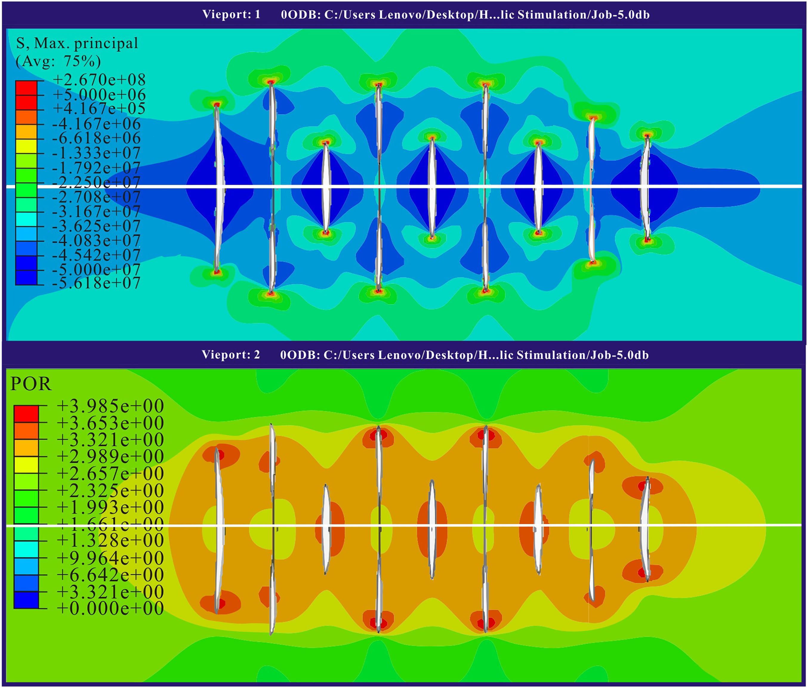
Case I—Constant injection model: Figure 6 is the stress nephogram and fluid pressure cloud map of multi-perforation clusters propagation in the horizontal well under constant injection. The simulation results show that the hydraulic fractures in each perforation cluster expand non-uniformly, and there is strong stress interference between the clusters of fractures when the constant injection method was subjected.
In addition, the fluid pressure cloud map of the multi-perforation cluster in horizontal wells shows that, for the constant injection, the propagation of the middle fractures (L2, L4, L6, and L8) would compress the fractures at both ends (L1, L3, L5, L7, and L9), resulting in better propagation of the middle fractures, and the length of the fractures at both ends is significantly lower than that of the middle fractures (Figure 6).
Thus, the fractures were uniformly divided into dominant fractures and non-dominant fractures. The non-dominant fractures are hydraulic fractures whose propagation is limited due to the effect of stress shielding (L1, L3, L5, L7, and L9); while the dominant fractures are hydraulic fractures that are not disturbed by stress shielding and thus expand well (L1, L3, L5, L7, and L9).
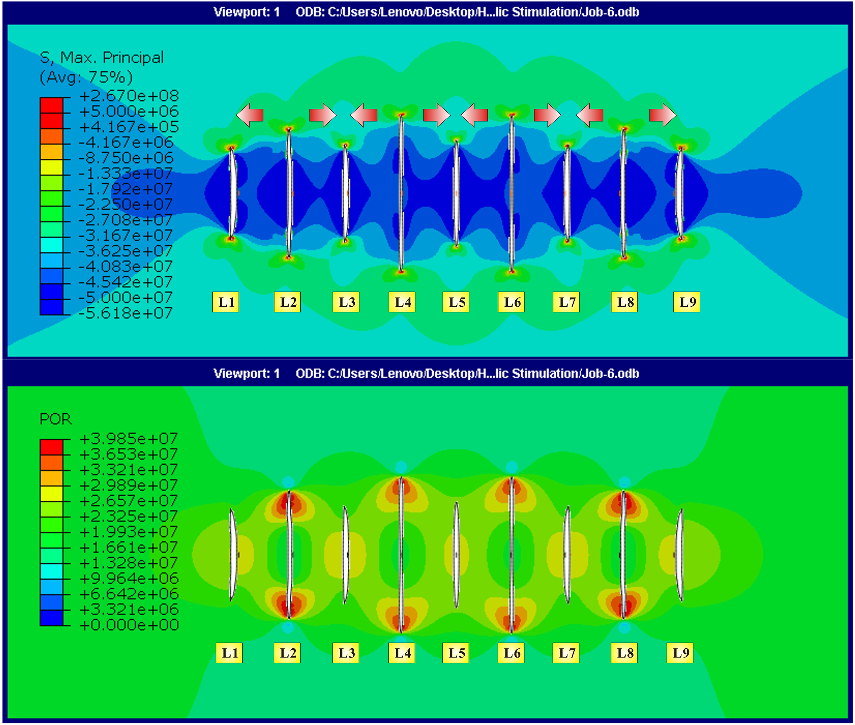
Case II—Pulse injection model: Figure 7 is the stress nephogram and fluid pressure cloud map of multi-perforation clusters propagation under the pulsed injection. Compared with the constant injection method, the pulsed injection enables a further growth of some perforation clusters. However, this growth is not uniform, and the dominant fractures with less stress interference increase more (L2, L4, L6, and L8), and the lengths of the fractures at both ends are almost unchanged.
In addition, from the comparison of stress nephograms, the pulse injection method makes the interference between fractures more serious, and the increased fluid internal pressure cannot overcome the stress interference, resulting in the fractures (L3, L5, L7, and L9) at both ends almost unchanged (Figure 7). This is because the fluctuating pressure attenuates significantly during the propagation of the horizontal stage (from the heel to the toe of the horizontal perforation section) (He et al., 2018).
Comparison of the constant and pulse injection method: The pressure curves of constant injection and pulse injection are obviously different. The pressure fluctuation formed by the pulse injection method will lead to rock fatigue to a certain extent, and the breakdown pressure is obviously lower than that of constant injection. In addition, after the rock breakdown, the injection pressure of constant injection is in a single deadlock relationship with fracture propagation (horizontal section), while the pulse injection method can continuously produce large pressure fluctuations, resulting in the pressure of maintaining fracture propagation being significantly greater than that of the constant injection method (Figure 8).
Compared with the constant injection, the pulsed injection can further promote the propagation of fractures, and the hydraulic fracture lengths of the L1, L2, L4, L6, L8, and L9 perforation clusters increased by 87%, 64%, 38%, 35%, 14%, and 6%, respectively (Figure 9). The reason is that the unstable injection displacement and pressure will generate a large “pressure vibration” and propagate along the wellbore in the form of pressure vibration wave. The pressure vibration wave can propagate through the perforation channels, and thus artificially increases a certain internal pressure in the fractures. The increase of pressure will eventually lead to the further propagation of the fractures, greatly improving the effect of HF (Figure 8). However, this growth is not uniform, and the fractures (L3, L5, L7, and L9) at both ends that are seriously disturbed by stress remain almost unchanged (Figure 9).
Stress nephogram and fluid pressure cloud map of the multi-perforation clusters propagation under constant injection (NO. A1).
Stress nephogram and fluid pressure cloud map of multi-perforation clusters propagation under pulsed injection (NO. A2).
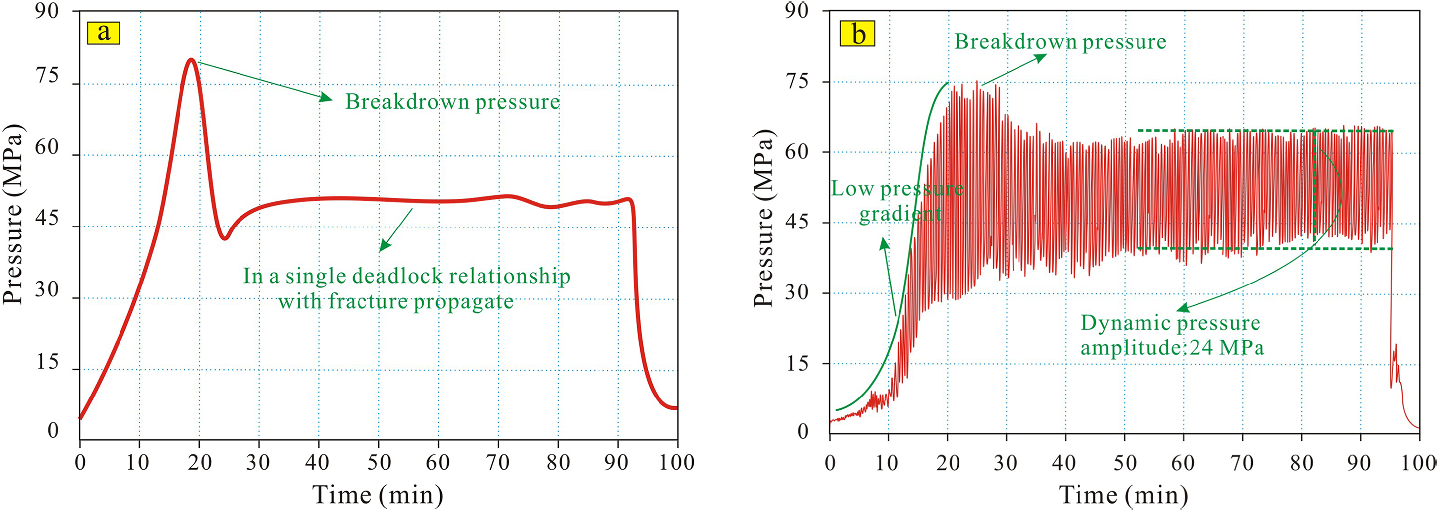
Comparison of injection pressure curves between constant injection and pulse injection.
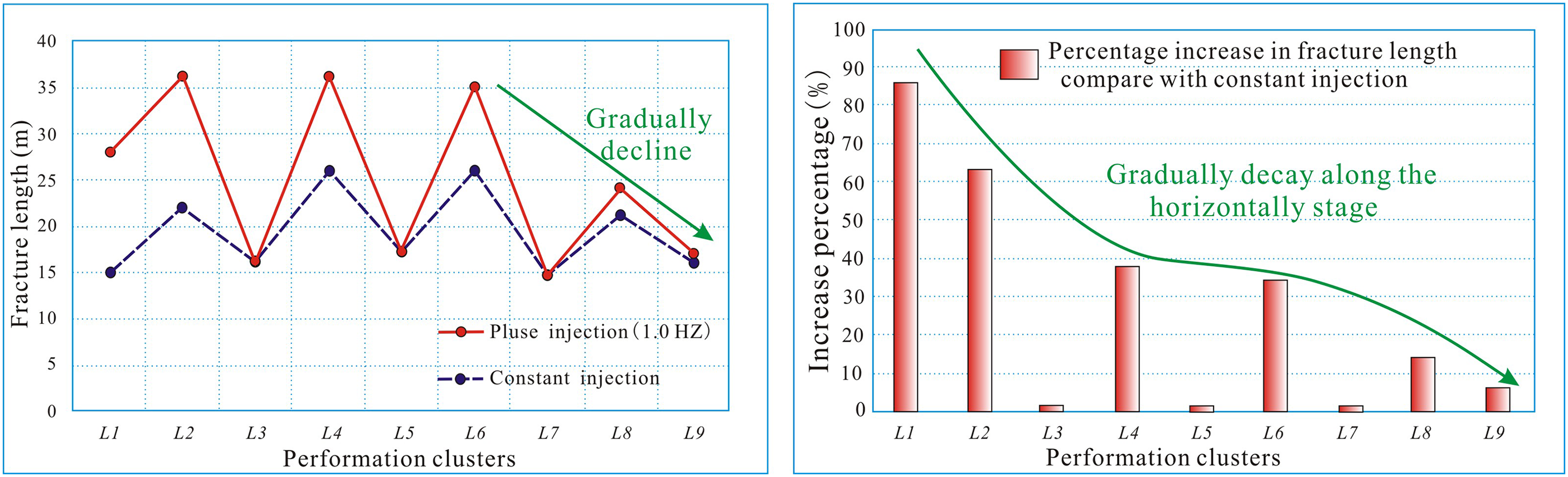
Comparison of fracture length of each perforation cluster by constant and pulse injection.
The synergistic effect of pulse frequency and displacement
Studies have shown that the injection displacement and pulse frequency play a key role in the balanced propagation of multi-perforation clusters in multistaged fracturing of horizontal wells during pulse injection fracturing. Thus, to explore the pulse injection method that enables more perforation clusters to effectively initiate and propagate uniformly, the initiation and propagation of the fractures of each perforation cluster under the change of pulse frequency and injection displacement were further analyzed.
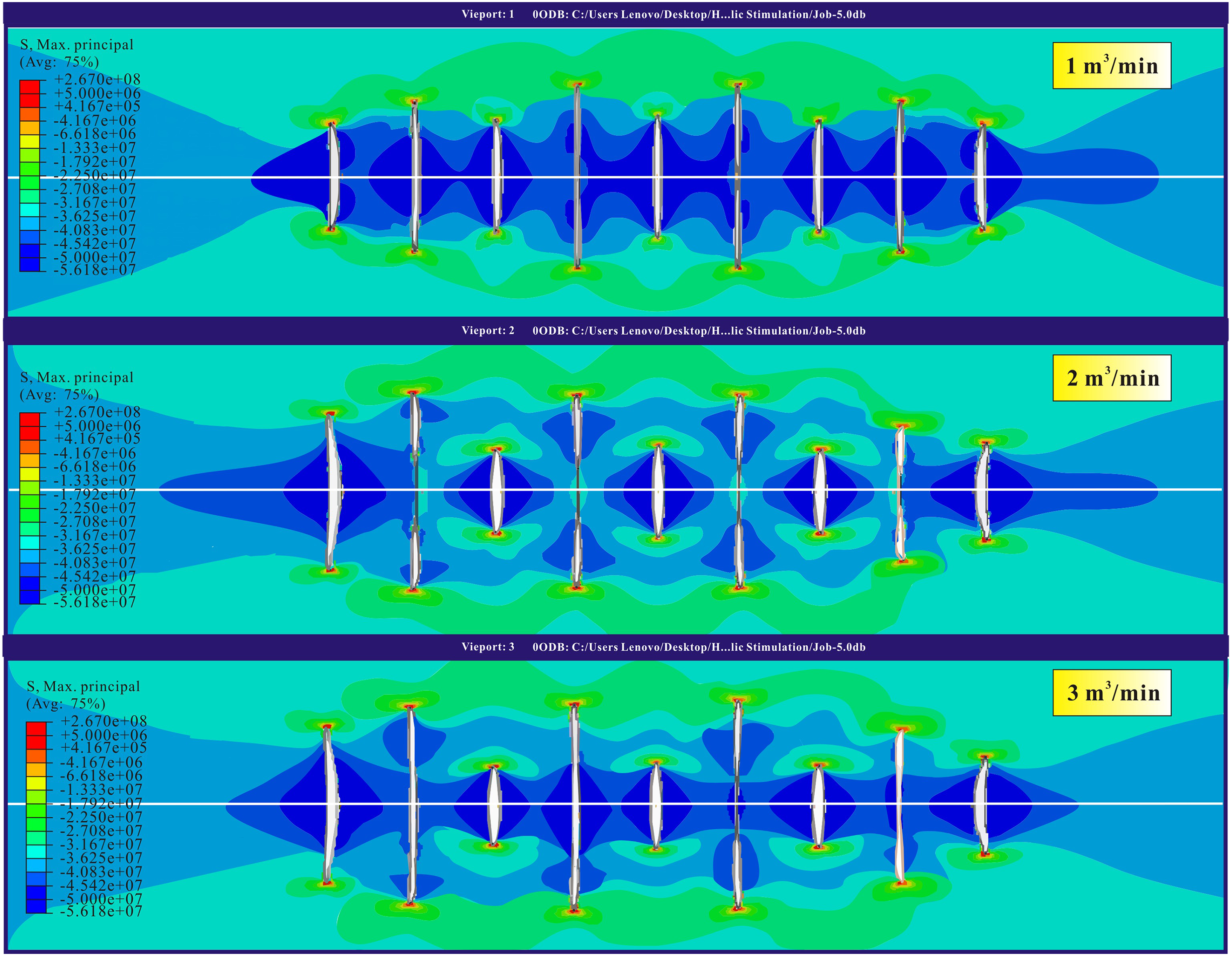
Injection displacement: Keeping the pulse frequency consistent (1.0 Hz), three levels of injection displacement of 1 m3/min, 2 m3/min, and 3 m3/min were set. Compared with the injection displacement of 2 m3/min, the length of fractures at both ends (L3, L5, L7, and L9) seriously disturbed by stress has been further increased at a lower injection flow rate of 1 m3/min. However, due to the low injection displacement, the fluid pressure in the fracture is relatively low, and the dominant fractures length, such as the perforation clusters of L2, L4, L6, and L8, are relatively short (Figure 10). The comparison of the stress nephogram by 2 m3/min and 3 m3/min shows that at higher injection displacements (3 m3/min), the dominant fractures, namely L2, L4, L6, and L8 perforation clusters have been further extended. This is because, compared with 2 m3/min (the amplitude of pressure = 24 MPa, maintain fracture expansion after the rock breakdown), higher injection rate (3 m3/min) will form a stronger pressure amplitude (35 MPa) in the reservoir, and higher-pressure amplitude will inevitably promote further expansion of the fracture (Figure 11). However, compared with the dominant fractures, the no-dominant fractures at both ends with stronger stress interference, that is, the fracture lengths of L1, L3, L5, L7, and L9 are significantly lower than those with low injection displacement (Figure 11). This is because, although the higher injection rate will increase the fluid pressure in the fracture, it will also further increase the stress shielding effect of the fracture. When the increased fluid pressure cannot overcome these additional stress-shielding effects, the fracture naturally cannot continue to propagate. Therefore, compared with the dominant fractures, the propagation of these non-dominant fractures disturbed by stress will be further limited. The results are consistent with the actual fracturing site, that is, higher injection displacement will promote the propagation of dominant fractures and inhibit the propagation of non-dominant fractures, thereby further aggravating the non-equilibrium development among perforation clusters. Pulse frequency: On the basis of keeping the same injection displacement (2 m3/min), the influence of pulse frequency on the fracture propagation of each perforation cluster was further analyzed. Under the different injection frequencies, the fracture propagation of each perforation cluster is mainly controlled by stress, which still shows that the dominant fractures are extremely developed, and the propagation of the non-dominant fractures is restricted (Figure 12).
Stress nephogram of multi-perforation clusters propagation (upper: A1; lower: C2).
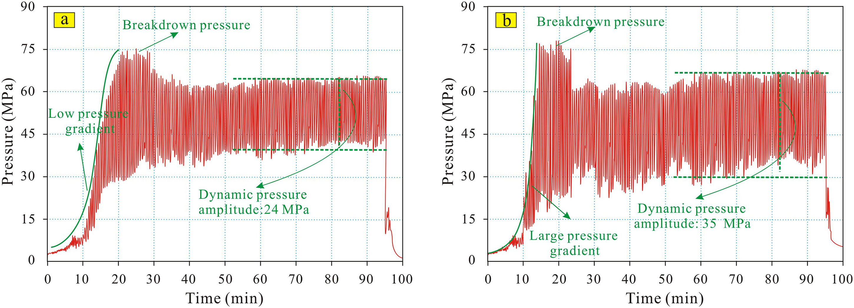
Comparison of injection pressure curves between different injection displacements (left: 2 m3/min; right: 3 m3/min).
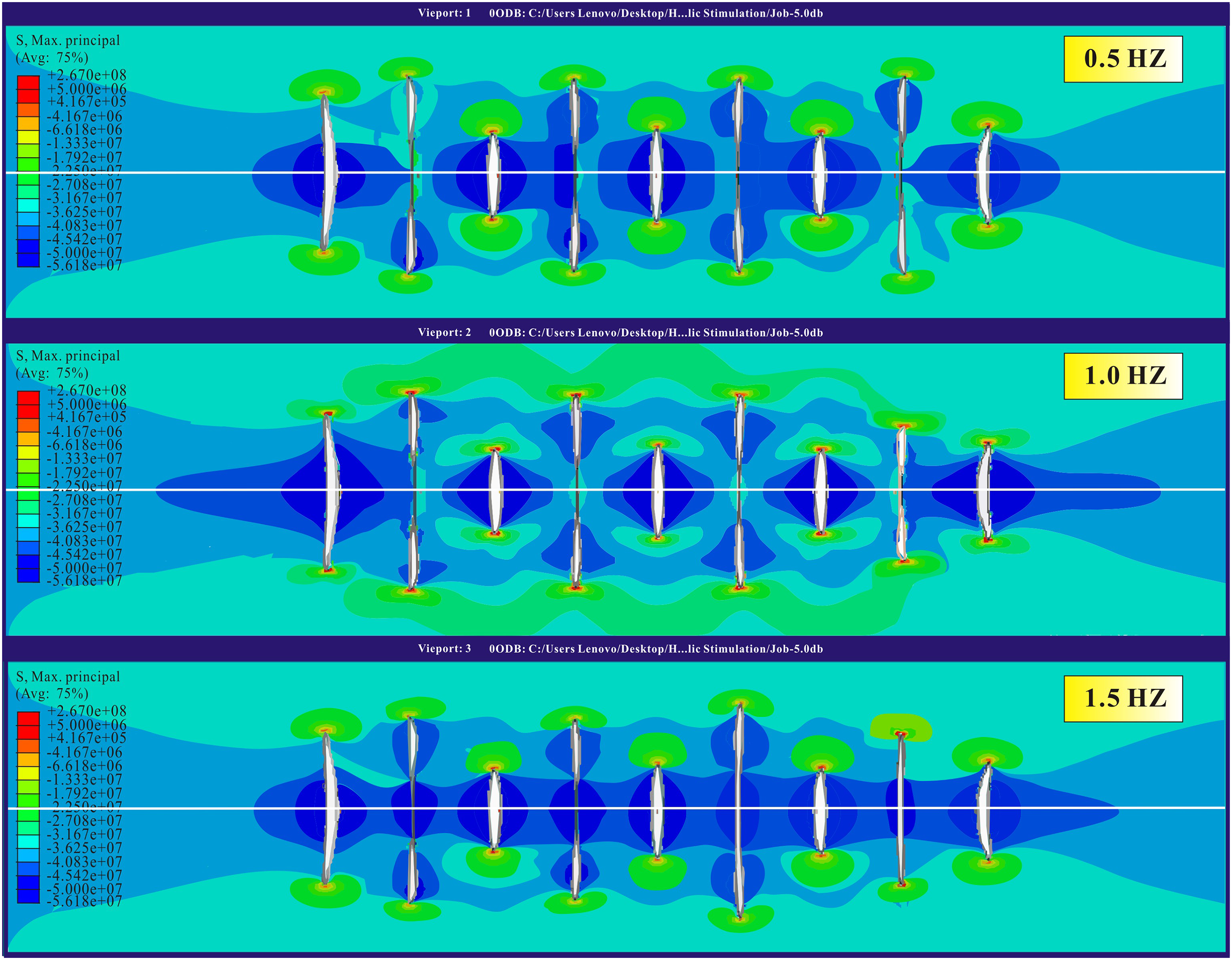
Stress nephogram of multi-perforation clusters propagation (upper: A1; lower: B1).
The change of pulse frequency during the pulse injection HF has a limited influence on the propagation of fractures in the shale gas horizontal well. However, it is worth noting that the fluid amplitude of low-frequency injection has strong attenuation resistance along the horizontal stage, and the low-frequency injection is beneficial to the propagation of the toe in the horizontal stage (Figure 12).
Compared to high-frequency fluid injection, the pressure amplitude generated by low-frequency has a strong anti-attenuation ability along the horizontal section, and at the toe of the horizontal section, the fluctuation amplitude of the fluid can still maintain a certain fluctuation range (Figure 13). Therefore, compared with the higher pulse frequency, the low-frequency injection is beneficial to the propagation of the toe in the horizontal stage.
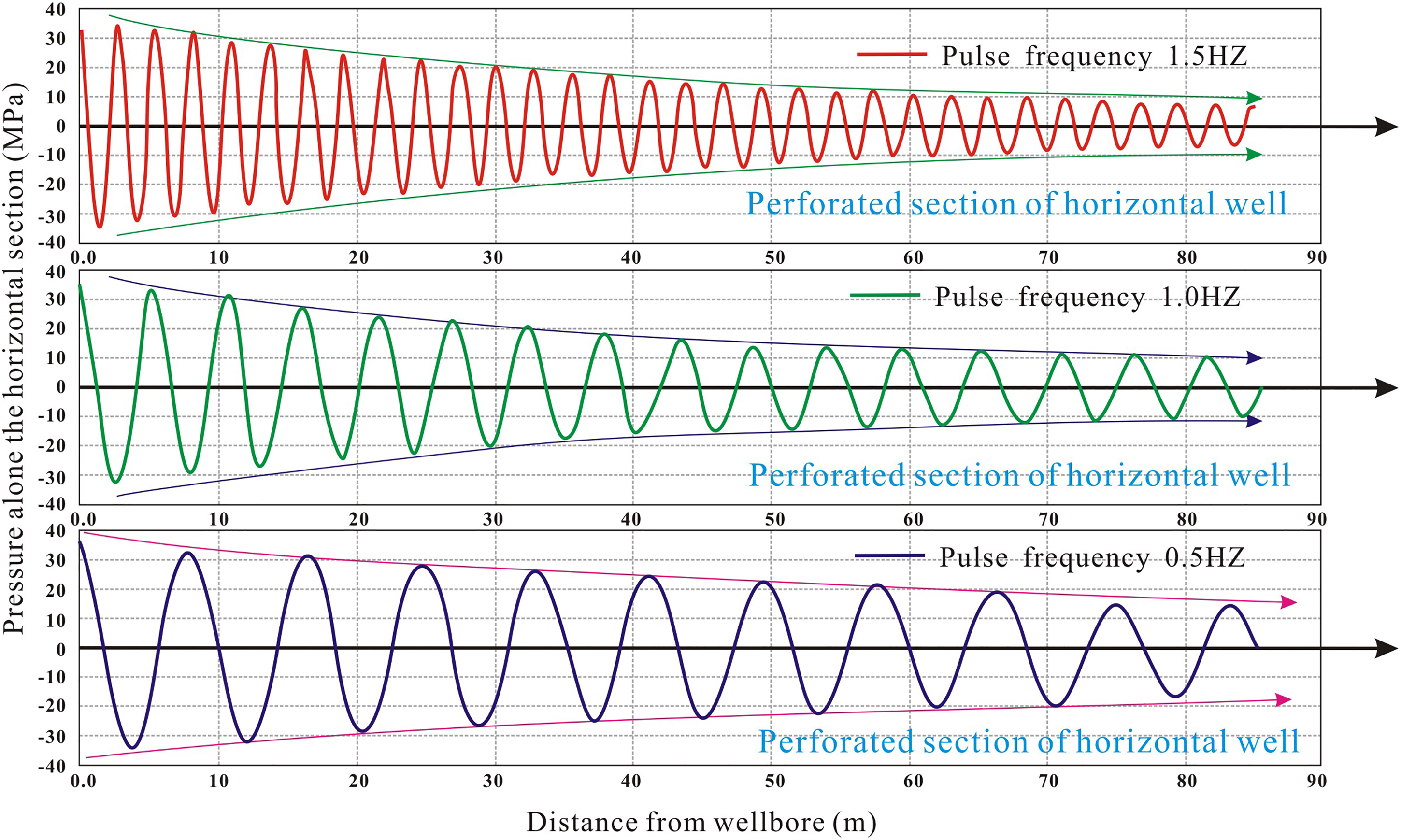
Propagation of pressure amplitude along horizontal section under different pulse frequencies.
Control method for multi-cluster fractures uniform crack and propagation
The pulse injection helps to improve the fracturing effect, but the method cannot completely overcome the stress interference effect. To achieve the goal of balanced propagation of each perforation cluster, the dominant fractures (L2, L4, L6, and L8) were temporarily plugged, and the application of temporary shielding technology in pulse injection HF was further explored (Figure 14).
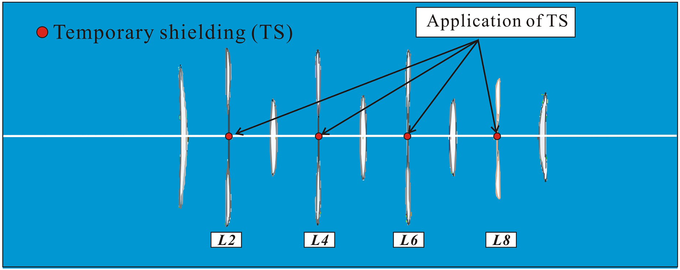
Application of temporary shielding technology in pulse fracturing model.
Since the fracturing fluid no longer enters the perforation cluster, the fluid pressure in the dominant fractures subside significantly. As the pressure of the dominant fractures subside, the compressive stress from the middle to both ends will also disappear. Additionally, after the dominant fractures were temporarily shielded, the fluid begins to re-enter the fractures at both ends, and the fluid pressure further increases. Coupled with the disappearance of compressive stress formed by stress interference, these non-dominant fractures have been greatly expanded (Figure 15).
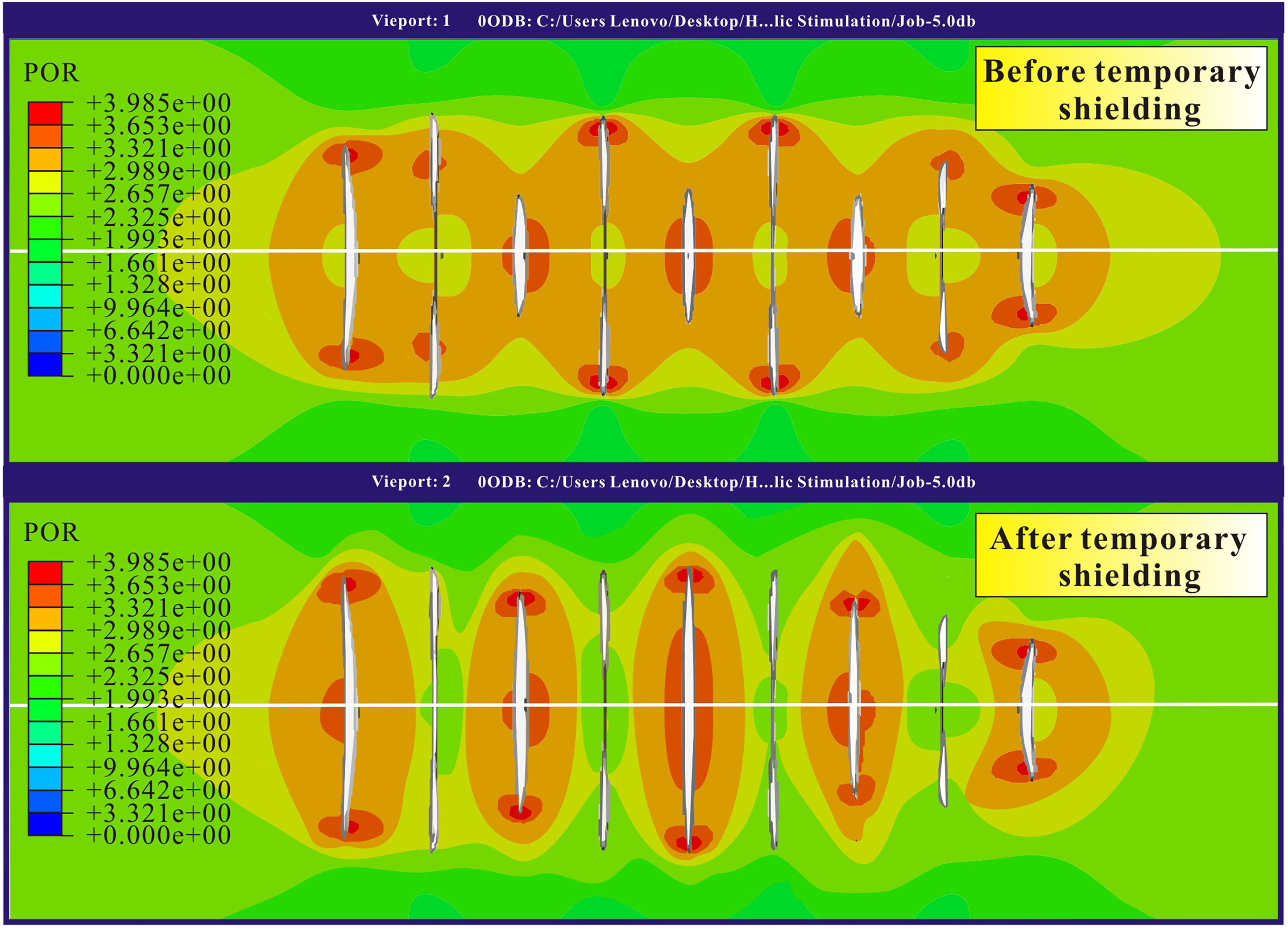
Fluid pressure of the multi-perforation clusters before and after temporary shielding.
After the dominant fractures were temporarily shielded, the fluid pressure of the non-dominant fractures disturbed by stress compression increased, and the hydraulic fractures have been further expanded. The non-dominant fractures, namely L1, L3, L5, L7, and L9, increased in length by 17%, 46%, 51%, 42%, and 5%, respectively (Figure 16).
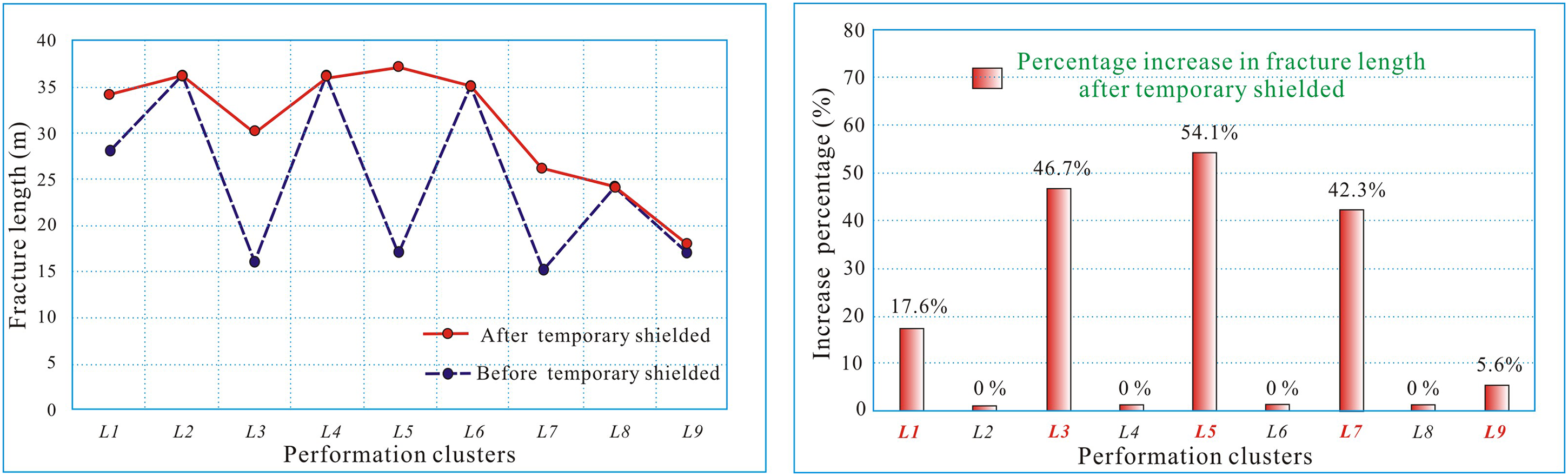
Comparison of fracture expansion before and after temporary shielding (left: line chart; right: histogram).
Thus, it can be seen that the reasonable application of composite temporary shielding agent combined with pulse injection technology in multistaged HF of horizontal wells can achieve balanced initiation and propagation of fractures in each perforation cluster, thereby improving the hydraulic stimulation effect of horizontal wells.
Conclusions
To evaluate the influence of pulse injection methods on the multi-fractures’ geometry and stress interaction in the multistage fracturing technology, a HF model coupling the fracturing fluid flow along the fracture and the rock deformation was adopted. For the first time, the effects of pulse injection methods on the initiation and propagation of multiple fractures were determined, and a new composite staged HF scheme suitable for horizontal wells with pulse-temporary shielding in shale reservoirs was further proposed. The main conclusions are as follows:
The pules-injection fracturing method and the contestant-injection fracturing method were compared. Compared with the constant injection method, the pulse injection can generate pressure waves, which increase the fluid pressure and promote the further propagation of fractures. However, this growth is not balanced, in which the fractures at both ends (L3, L5, L7, and L9) seriously disturbed by stress are almost unchanged. The effects of key pulse injection parameters (pulse displacement and pulse frequency) on the initiation and propagation of multiple fractures were determined. The results show that the pulse injection helps to improve the fracturing effect, but no matter how the pulse displacement and pulse frequency change, the pulse injection cannot completely overcome the stress interference effect and achieve the balanced development of each perforation cluster. The reasonable application mode of temporary shielding in multistaged fracturing of horizontal wells under the pulse injection HF was determined, and a new composite multistaged HF scheme suitable for horizontal wells with pulse-temporary shielding in shale reservoirs was proposed. The result shows that the application of composite pulse-temporary shielding can achieve balanced initiation of fractures in each perforation cluster.
Footnotes
Declaration of conflicting interests
The author(s) declared no potential conflicts of interest with respect to the research, authorship, and/or publication of this article.
Funding
The author(s) disclosed receipt of the following financial support for the research, authorship, and/or publication of this article: This study is jointly supported by the National Natural Science Foundation of China (No. 52174017), Open Fund of the Key Laboratory of Geothermal Resources of the Ministry of natural resources (No. KLDGR2022G05), and Open Fund of Hubei Key Laboratory of Drilling and Production Engineering for Oil and Gas, Yangtze University (No. YQZC202104).