
Abstract
Hydraulic fracturing is one of the most important technologies for shale gas production. Complex hydraulic fracture networks can be stimulated in shale reservoirs due to the existence of numerous natural fractures. The prediction of the complex fracture network remains a difficult and challenging problem. This paper presents a fully coupled hydromechanical model for complex hydraulic fracture network propagation based on the discontinuous deformation analysis (DDA) method. In the proposed model, the fracture propagation and rock mass deformation are simulated under the framework of DDA, and the fluid flow within fractures is simulated using lubrication theory. In particular, the natural fracture network is considered by using the discrete fracture network (DFN) model. The proposed model is widely verified against several analytical and experimental results. All the numerical results show good agreement. Then, this model is applied to field-scale modeling of hydraulic fracturing in naturally fractured shale reservoirs. The simulation results show that the proposed model can capture the evolution process of complex hydraulic fracture networks. This work offers a feasible numerical tool for investigating hydraulic fracturing processes, which may be useful for optimizing the fracturing design of shale gas reservoirs.
Keywords
Introduction
Hydraulic fracturing is a key technology for stimulating oil and gas wells to increase their productivity. Especially in shale gas production, the ultralow permeability of reservoirs requires a large fracture network to maximize well performance, and hydraulic fracturing has made it possible for commercial production by means of multistage fracturing of horizontal wells (Britt and Schoeffler, 2009; Jang and Lee, 2015; Mayerhofer et al., 2010; Shen et al., 2016, 2018b). Hydraulic fracturing is a typical hydromechanical coupling problem that involves the coupling of at least three processes (Adachi et al., 2007): rock mass deformation under the effect of fluid pressure, fluid flow within fractures and fracture propagation. In addition, different from conventional reservoirs, shale reservoirs contain plenty of natural discontinuities, including bedding planes, joints, faults, etc. Complex fracture networks instead of simple parallel fractures are understood to be stimulated by multistage fracturing as a result of the activation of pre-existing natural discontinuities. Thus, due to the complex coupling processes and strong interaction between hydraulic fractures (HFs) and natural fractures (NFs), the investigation of complex HF networks is a great challenge (Lecampion et al., 2018; Weng, 2015). Some analytical or semianalytical fracturing models have been developed in the past several decades, such as the PKN model (Nordgren, 1972), KGD model (Geertsma and De Klerk, 1969), pseudo-3D model (Advani et al., 1990), planar-3D model (Siebrits and Peirce, 2002), etc. Although the basic mechanism of hydraulic fracturing has been generally understood by using these models, complex HF networks cannot be predicted because these models are both based on the simple assumption of a bi-wing fracture. In addition to the above traditional models, laboratory testing is another rising method for investigating the fluid flow and fracture propagation within shale samples (Guo et al., 2020; Shen et al., 2019; Yang et al., 2020; Zou et al., 2016b). The HF network configuration could be observed by some advanced monitoring and scanning techniques (Li et al., 2018; Qian et al., 2020; Wang et al., 2020a, 2020b), but the fracture propagation processes are still very difficult to detect. In addition, it is very difficult to relate the experimental results to field operations (McClure and Horne, 2014). At present, the hydraulic fracturing operations still heavily rely on imprecise estimates of the stimulated reservoir volume derived from microseismic observations and through a highly inefficient “trial-and-error” strategy (Weng, 2015). Thus, to optimize fracturing operations and further promote shale gas recovery, there is an urgent need to develop more efficient approaches for predicting complex HF networks.
With the rapid development in recent years, numerical techniques have been regarded as reliable and flexible tools for predicting HF networks and other related problems (Liu et al., 2019; Weng, 2015). Compared to field monitoring and laboratory experiments, numerical simulation can capture the processes of HF network propagation, and all the details can be exported for analysis. A bridge between research and practice could therefore be built. Hence, the development of numerical models for hydraulic fracturing has drawn increasing attention from researchers and engineers (Dahi Taleghani et al., 2016; Lecampion et al., 2018; Weng, 2015). Generally, the commonly applied numerical methods for hydraulic fracturing can be classified into two groups in terms of the continuity hypothesis: continuum-based methods and discontinuum-based methods (Jiao et al., 2015). The most typical continuum-based methods for simulating hydraulic fracturing are the methods based on the finite element method (FEM), including the cohesive zone method (CZM) (Carrier and Granet, 2012), extended finite element method (XFEM) (Dehghan et al., 2017) and XFEM-based CZM (Feng and Gray, 2019). Special elements or enrichment functions have been successfully developed for FEM to realize the simulation of fracture propagation. As the mature framework of FEM is relatively easy to follow and there are many convenient FEM software packages, the above methods have been widely used to investigate hydraulic fracturing problems, such as fracture-height containment (Yue et al., 2019), fracturing-induced fault slip (Khoei et al., 2016), stress shadow effect (Salimzadeh et al., 2017), etc. However, in the case of two or more fractures intersecting with each other, because of the singularity of the fracture tip stress field, the solution process of the FEM will encounter mathematical difficulties (Jiao et al., 2015). In addition to the FEM-based methods, some new continuum-based methods, such as phase-field (Chukwudozie et al., 2019; Miehe and Mauthe, 2016), peridynamic (Ni et al., 2020; Ouchi et al., 2015), flow-stress-damage (Rui et al., 2018), and meshfree methods (Oliaei et al., 2014), have also been introduced to simulate hydraulic fracturing problems recently. These new methods show some advantages compared to conventional methods, but there are some obvious limitations because of the assumptions used to develop coupled models. In general, for continuum-based methods, considering the complex NF networks of shale, as well as the interactions of multiple fractures, modeling is still quite difficult at present.
Compared with continuum-based methods, discontinuum-based methods have inherent advantages in characterizing naturally fractured rock masses. In discontinuum-based methods, the rock mass is discretized as blocks or particles, between which fractures are represented by broken bonds and are supposed to develop automatically without remeshing (Choo et al., 2016). Thus, NFs can be explicitly represented, and the interaction of multiple fractures can be modeled without encountering mathematical problems (Jiao et al., 2015). The most commonly used discontinuum-based method for hydraulic fracturing is the explicit discrete element method (DEM), which is represented by several commercial programs, including UDEC, 3DEC and PFC. It is widely recognized that the DEM shows many advantages in dealing with NF networks and multiple fracture interactions (Damjanac and Cundall, 2016; Zhang et al., 2019). Significant progress has been achieved in simulating complex HF networks in recent years. For example, Nagel et al. (2013) investigated the configurations of three-dimensional (3D) HF networks in formations with highly-developed and random NF networks. Zou et al. (2016a) investigated the large-scale HF network initiated from multiple perforation clusters. Kwok et al. (2020) investigated the effects of joint characteristics on the behavior of shale formation during fracturing operations. In addition to explicit DEM, the finite-discrete element method (FDEM), a hybrid method of the DEM and FEM, has recently become another useful method for solving hydraulic fracturing problems (Lisjak et al., 2017; Yan et al., 2016). However, although the explicit DEM and FDEM have many advantages in simulating complex HF networks compared to continuum-based methods, some limitations still exist. Since the dynamic relaxation method (Jiao et al., 2004) is employed to explicitly solve the block motion, the use of numerical damping and a small time step cannot be avoided. DEM and FDEM suffer a lot from these two troublesome parameters, and the explicit procedure used by FDEM and DEM may show a reduced efficiency for quasi-static problems including hydraulic fracturing.
As a member of the family of discontinuum-based numerical methods, the discontinuous deformation analysis (DDA) method is another emerging method for hydraulic fracturing simulations. DDA is a fully implicit version of the DEM and was first developed by Shi (1988). As a theoretically rigorous numerical method, DDA has been one of the focuses in the discontinuous computing field since its development (Jiao et al., 2017). Similar to FEM, DDA establishes synchronous equilibrium equations by minimizing the total potential energy of the whole block system. The equilibrium conditions are automatically satisfied for quasi-static problems without the need to use the excessive iteration cycles used in the explicit DEM (Jing and Stephansson, 2007). In addition, similar to the explicit DEM, every element can move and deform independently so that complex discontinuous problems can be simulated without encountering mathematical difficulties. Moreover, elements with arbitrary geometry can be used for DDA calculations; thus, dense and complex NF networks can be easily represented in a DDA model. Because DDA retains the advantageous features of both FEM and explicit DEM, it is considered one of the highest-potential discontinuum methods in rock mechanics (Jiao et al., 2004). After development over the past three decades, DDA has been widely used to analyze discontinuous problems and its advantages in modeling naturally fractured rock masses have been widely recognized. Many DDA-based coupled models have been developed to investigate fracture seepage and solid deformation in naturally fractured rock masses (Chen et al., 2013; Jing et al., 2001; Kim et al., 1999). However, these studies did not consider the fracture propagation process. The applications for hydraulic fracturing have only appeared in recent years. Ben et al. (2012) first attempted to simulate hydraulic fracturing with DDA, but only a very simple example of bi-wing HF was simulated, and no verification example was given. Jiao et al. (2012) extended DDA for fracture propagation and developed a coupled model to simulate hydraulic fracturing (Jiao et al., 2015). Some simple verification examples were given in their work. Morgan and Aral (2015a) developed an implicitly coupled hydromechanical model for HF simulation based on DDA. They also made some attempts to simulate the interaction of HF and NF (Morgan and Aral, 2015b). Choo et al. (2016) proposed a hybrid FEM-DDA model for hydraulic fracturing, where the efficiency and accuracy of the original DDA can be improved. In general, although DDA has great potential for studying hydraulic fracturing processes in naturally fractured media, related research is still lacking. Previous studies have mainly focused on the implementation of coupled hydromechanical models and preliminary verifications. Only simple examples were introduced, and the simulations of complex HF networks in highly fractured rock masses have not been involved.
In this paper, a fully coupled hydromechanical model for complex HF network propagation is developed based on DDA. Compared with previous DDA-based models, this model realizes the simulation of complex HF networks in naturally fractured rock masses. The fully hydromechanical coupling processes are implemented by using an efficient iteration algorithm, and the NFs are considered by the discrete fracture network (DFN) model. In addition, the proposed model is widely verified against analytical solutions, classical hydraulic fracturing models and laboratory fracturing experiments, and all results show good agreement. Moreover, field-scale modeling of complex HF networks in a naturally fractured shale reservoir is conducted. The simulation results show that the proposed DDA-based numerical approach can capture the evolution process of complex HF networks, which is typically neglected in continuum-based methods and previous DDA-based models.
Fundamentals of DDA
DDA is a fully implicit form of the DEM for analyzing the motion of discrete rock blocks and was first developed by Shi (1988). DDA inherits some characteristics from both the FEM and explicit DEM. As shown in Figure 1, DDA treats the rock mass as an assemblage of rock blocks, which are regarded as homogeneous, isotropic and linearly elastic media. Every block can move and deform independently so that complex discontinuous problems can be simulated without encountering mathematical problems. The fundamental equations of DDA are derived from the principle of minimum potential energy. The penalty function method is used to meet the nonpenetration constraint of block contacts. The readers who are interested in the details of DDA can refer to the reference (Shi, 1988). Only a brief introduction is given here.
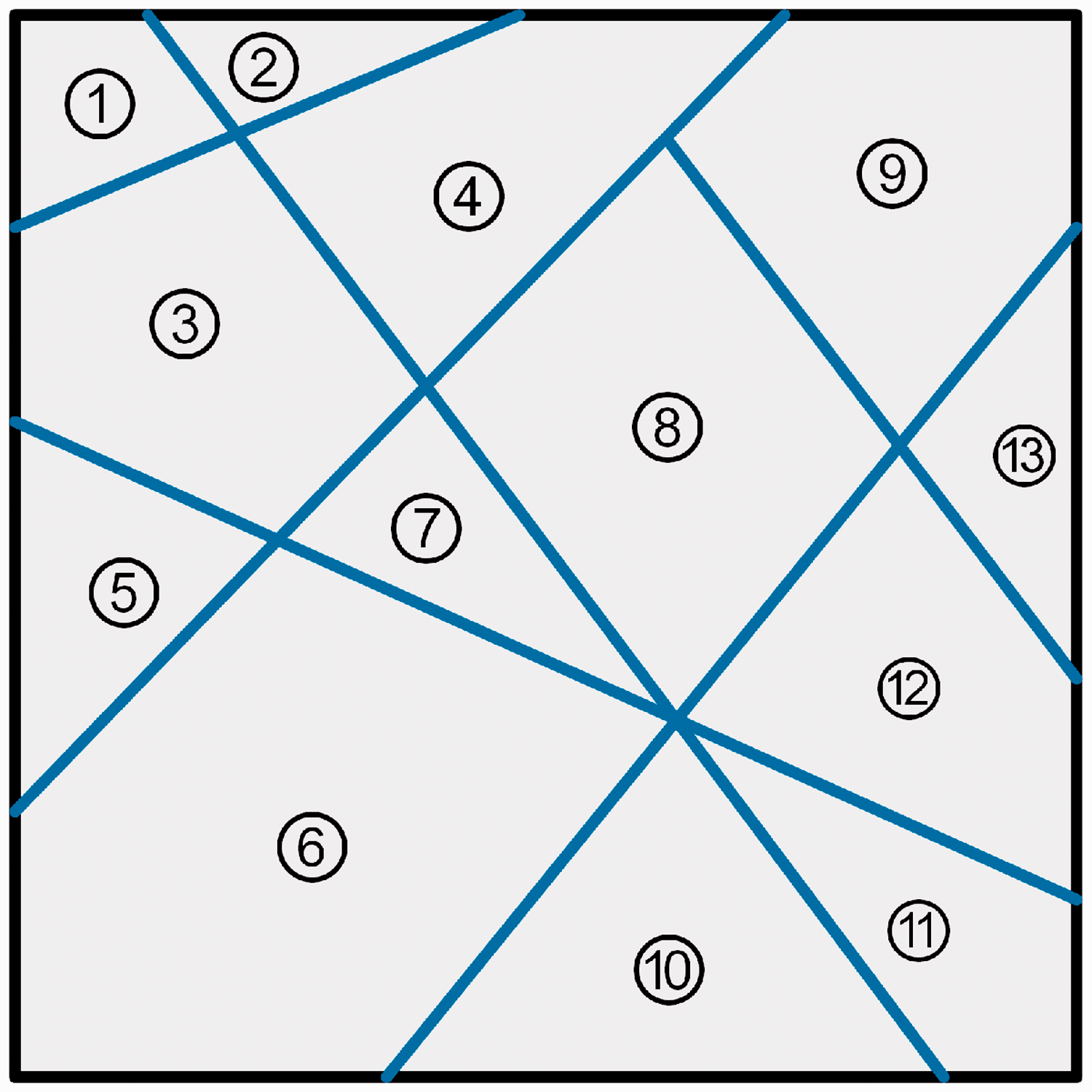
Typical block system of 2 D DDA. 1–11 represent the rock blocks, and the blue segments represent the joints.
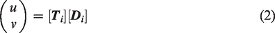
In DDA, each block element is assumed to have constant stresses and strains. In two-dimensional (2D) analysis, each block i has six degrees of freedom, which are mathematically expressed as follows:

Using a complete first-order approximation function, the displacement vector (u, v) of any point (x, y) within block i can be calculated by:

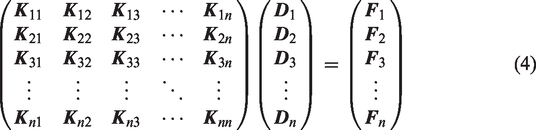
For a block system with n blocks, by minimizing the total potential energy done by the forces and stresses, the simultaneous equilibrium equations can be written as
In DDA, rock failure is initiated between blocks by either a tensile or shear stress. The fracture criteria consist of two parts. First, the maximum tensile strength criterion is used to determine the tensile failure along the normal direction of the block interface, which is written as


Hydraulic-mechanical model for DDA
In the hydraulic fracturing process, the fluid flow is influenced by the mechanical deformation, and conversely, fluid pressure acting on the fracture surfaces affects the mechanical deformation. As shown in Figure 2, the fluid flow in the fracture exerts compressive pressure on the walls of the fracture, which leads to an increase in the fracture aperture a. Meanwhile, the change in fracture aperture also changes the fracture conductivity, thus influencing the flow rate q and fluid pressure p.
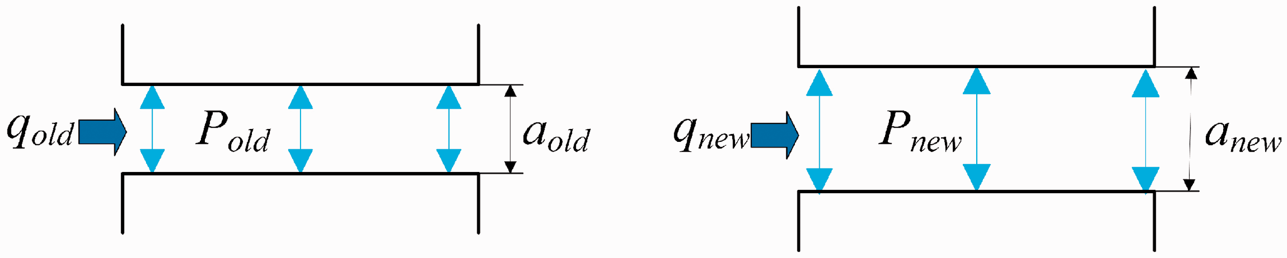
Hydromechanical coupling mechanism.
To implement the hydromechanical model into DDA, some assumptions are made to capture the basic idea of hydraulic fracturing and simplify the problem: (i) the rock matrix is impermeable; (ii) HFs are allowed to propagate along the block interfaces but cannot traverse the blocks; and (iii) the fluid flow within fractures is assumed to be laminar, viscous, and incompressible. Within these assumptions and the framework of DDA, the key points of this hydromechanical model are to simulate the fluid flow within fractures and consider the fluid pressure in DDA calculations. In addition, to simulate the complex HF network in shale reservoirs, the NF network should also be taken into account in the numerical model. Below, the fluid flow algorithm, the calculation of fluid forces acting on block boundaries and the implementation of the NF network are described in detail.
Fluid flow algorithm
Considering the characteristics of DDA, an efficient method for solving fluid flow within HFs is developed. The fluid network model (Figure 3) is established according to the typical block system shown in Figure 1. This model consists of flow channels and their intersections. The fluid flow channels are generated between blocks along the interfaces. They are connected by nodes (i, j, k, …, o) and their connection relationships are searched according to the schematics of blocks. Only the broken joints, corresponding to fractures, are taken into account in the fluid calculations. For a better illustration of the fluid flow calculation, a part of the fluid network with one intersection i and its surrounding flow channels (ij, ik) is detailed below.
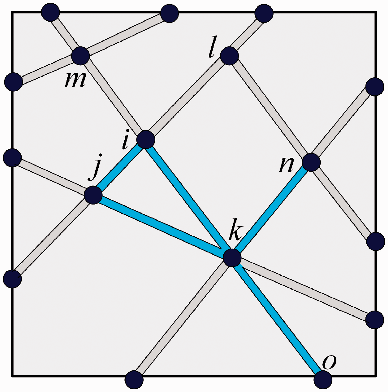
Fluid flow network of the coupled DDA model. The blue segments represent the broken joints that allow fluid flow, while gray segments represent the unbroken joints that do not allow fluid flow. The nodes (i, j, k, …, o) refer to the intersection points of flow channels, which are the vertices of blocks geometrically.
During the process of fluid flow, the principle of mass conservation should always be satisfied. The mass conservation for a single node i can be expressed as follows:

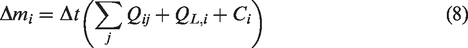
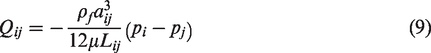
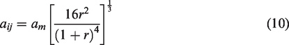
Under the assumption of viscous laminar flow, the mass flow rate between node i and node j obeys the cubic law:
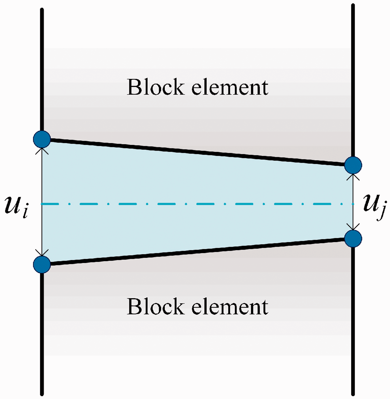
Normal displacement of two adjacent blocks.
where am = (ui + uj)/2, r = ui/uj, and ui and uj are the relative displacements at the two endpoints of block interface ij, respectively. Here, a minimum hydraulic aperture amin is set to avoid the fracture aperture being zero or negative. The equivalent aperture aij is set to amin in the case of
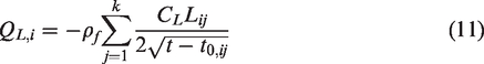
The leak-off effect is taken into account based on the classical Carter’s leak-off model (Settari, 1985). The mass rate of leak-off from node i into the rock matrix is expressed as
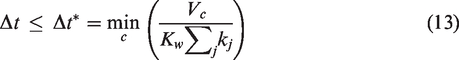
To maintain the numerical stability of this integration strategy, the hydraulic time step size Δt should be less than a critical value:
Calculation of fluid force acting on block boundaries
Similar to previous works (Jiao et al., 2015; Jing et al., 2001), the fluid pressure on block boundaries is treated as a linearly distributed loading. As shown in Figure 5, the fluid inside flow channel ij exerts compressive pressure on the lower boundaries of block 1 and upper boundary of block 2. pi (pix, piy) is the fluid pressure at node i, and pj (pjx, pjy) is the fluid pressure at node j. ξ (
Fluid pressure acting on block boundaries.
The potential energy of the fluid pressure acting on the boundary of block 1 is written as
By minimizing the potential energy of fluid pressure, the nodal load induced by the fluid pressure acting on the boundary of block 1 can be obtained as follows:
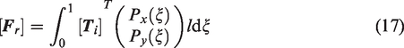
[
Implementation of the NF network
The NF network has a significant effect on the response of shale reservoirs to hydraulic fracturing. However, as the NFs in deep-buried shale reservoirs are highly random and unpredictable, the complete identification of the NF network is very difficult and almost impossible. The DFN model is adept at describing the random behavior of NFs. It starts with spatial statistics associated with a fracture network (fracture orientation, size, density, transmissivity, etc.) measured from cores, well tests, surface outcrops, etc., and these statistics are then used to generate realizations of fracture networks with the same spatial properties. Since the DFN model has been widely used in characterizing naturally fractured shale reservoirs (Weng, 2015), it is also used in this DDA-based model to characterize the NF network of shale reservoirs. The Poisson DFN model, also known as the Baecher model, is employed to generate fractures with random trace lengths and orientations. The fundamentals of the Poisson DFN model are beyond the scope of this paper but can be found in the reference (Baghbanan and Jing, 2007).
To implement the DFN model into DDA, the numerical model with generated NF networks needs to be meshed into block elements. The mesh quality is very important because it may greatly influence the convergence and computational efficiency of simulations. Here, the unstructured triangular grid is adopted to address the complex and dense pre-existing fractures within the model. The COMSOL Multiphysics software (Comsol, 2014) is very good at meshing the model containing numerous pre-existing fractures. It can maintain the complex geometry of the fracture network and avoid generating grids with bad quality. Thus, COMSOL is used to generate the block system for DDA calculations in this study. Then, the block interfaces corresponding to NFs are assigned a very small strength, while other block interfaces are assigned the strength of the intact rock. In addition, NFs are also assigned an initial fracture aperture and participate in fluid flow calculations. In this way, the interaction between newly-generated fractures and pre-existing fractures could be simulated.
The workflow
The workflow of the proposed hydromechanical model is shown in Figure 6. First, the reservoir model is established and the NF network is generated by a homemade DFN generator. Then, the model containing numerous pre-existing fractures is meshed in COMSOL, and a homemade interface program helps introduce the triangular grid from COMSOL to DDA. After that, the fracturing calculations can begin. An initial equilibrium under in-situ stresses and other boundary conditions should be obtained first, and then the fluid injection can start. The fluid pressure
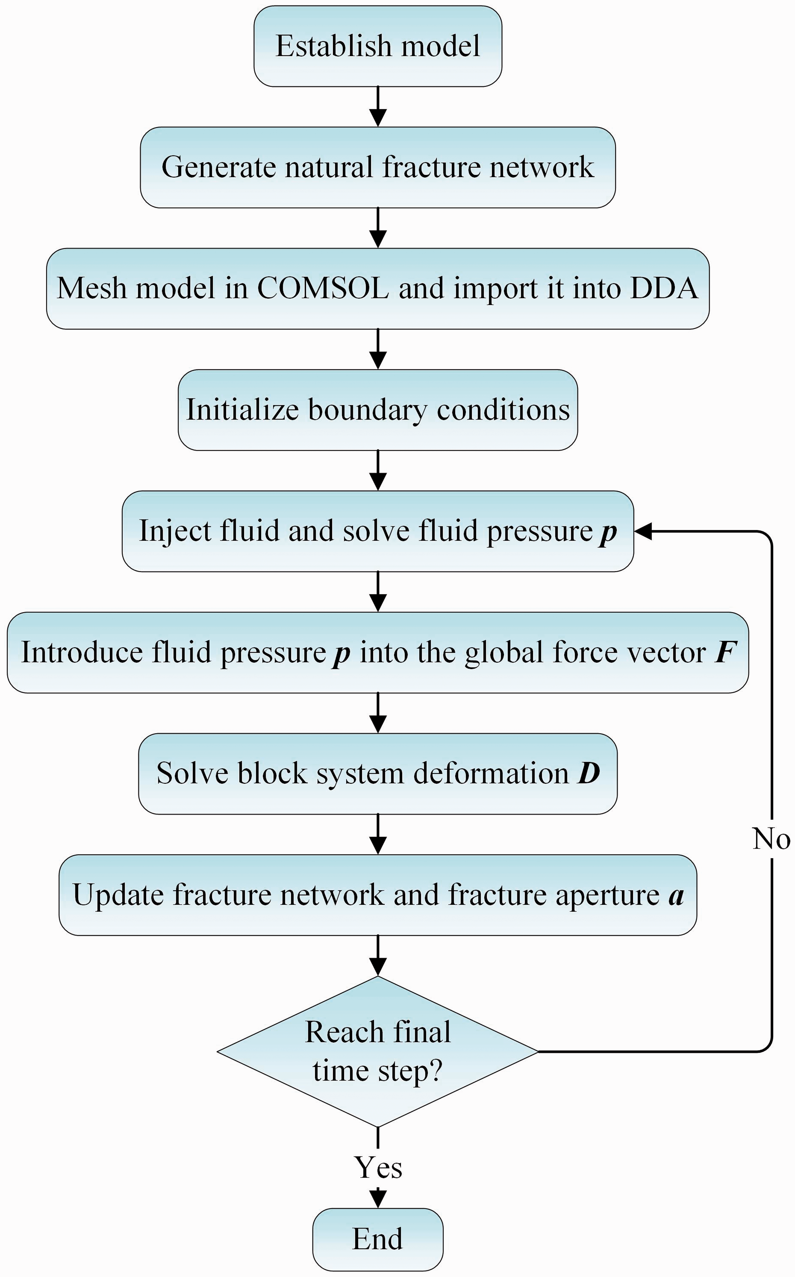
Workflow of the proposed hydromechanical model.
Model verification
In this section, the proposed model is widely verified against analytical and experimental results. Four examples are presented. First, the accuracy of DDA in calculating fracture aperture is tested by an analytical solution. Second, the fluid solvers are also tested by an analytical solution to examine the calculation of unsteady fluid flow in fractures. Then, the model is verified against the classical KGD model, by which the accuracy in simulating the propagation of a single HF is tested. Finally, the model is verified against laboratory fracturing tests, and the reliability in simulating complex HF networks is checked.
Fracture opening under constant pressure
This numerical example is developed to verify the accuracy of the model in calculating fracture aperture. As shown in Figure 7(a), a 4-m-long fracture is embedded in the center of the model, which is linearly elastic, isotropic and homogeneous. The vertical in-situ stress σv and horizontal in-situ stress σH are set to 7 MPa and 10 MPa, respectively. The two surfaces of fracture are subjected to a uniform and constant pressure, p0 = 10 MPa. Fracture propagation is not considered in this example. Under the loading of constant fluid pressure, the embedded fracture opens and becomes elliptical. The analytical solution for the fracture aperture is given by (Parker and Saunders, 1982)

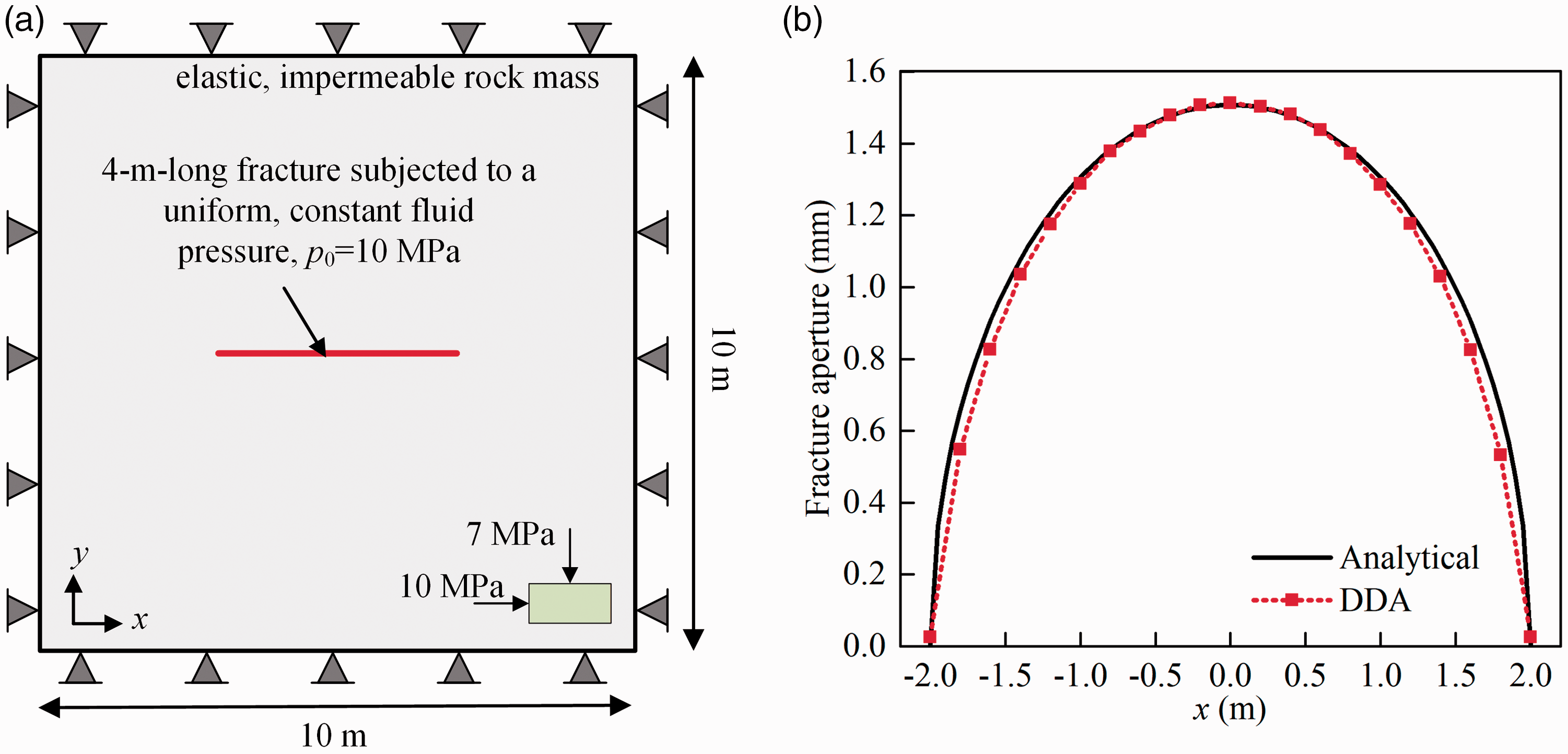
Fracture opening under constant internal pressure. (a) Model geometry and boundary conditions. (b) Comparison between analytical and numerical results of fracture aperture.
Unsteady flow in a single fracture
This example is developed to investigate the accuracy of the fluid algorithm in simulating the unsteady flow in a single fracture. As shown in Figure 8(a), a 1-m-long fracture is embedded in the center of the model. A constant fluid pressure p0 = 10 MPa is applied to the left end of the fracture. The fluid can only flow from the left to the right end of the fracture and cannot permeate into the model or flow out from the right end. The fracture is assigned a constant and uniform aperture, a = 0.03 mm. The analytical solution to this problem, which satisfies the above boundary conditions, can be expressed as (Jaeger and Carslaw, 1986)

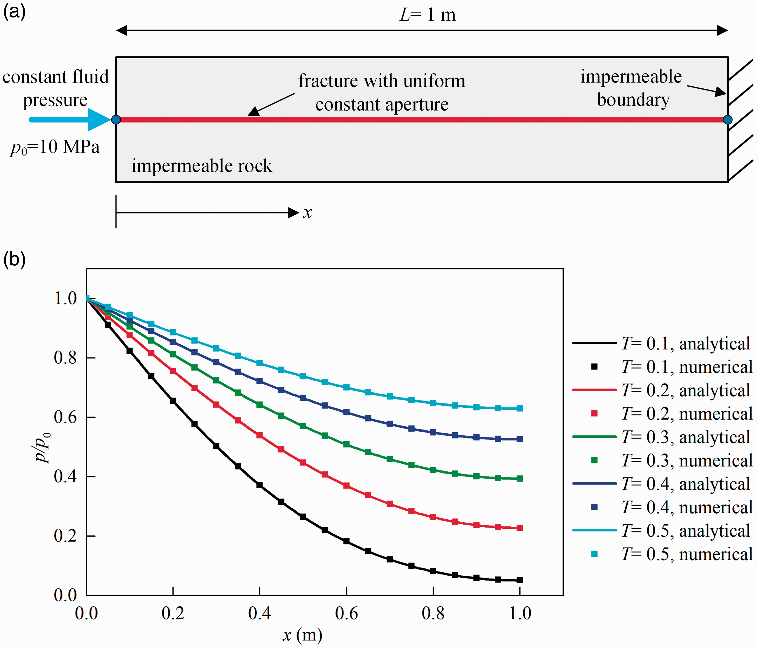
Unsteady flow in a single fracture. (a) Model geometry and boundary conditions. (b) Comparison between analytical and numerical results of fluid pressure distribution.
Verification against the KGD fracture model
This example is developed to verify the proposed model against the well-known KGD fracture model. As a classical method for numerical analysis of 2D hydraulic fracturing, the KGD model assumes that the rock mass is linearly elastic, homogeneous, isotropic and impermeable (Geertsma and De Klerk, 1969). The influence of fracture toughness is neglected, thus resulting in a viscosity-dominated regime of fracture propagation. According to the KGD model, the fracture half-length, fracture aperture and fluid net pressure at the injection point vary with time t as follows (Wasantha et al., 2017; Yew and Weng, 2014):
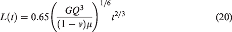
Based on the assumptions of the KGD model, a 2D plane-strain model is established (Figure 9(a)). The model is meshed by the unstructured triangular grid, in which the grid in the center of the model is refined to improve the accuracy. The following input parameters were used for simulations: G = 40 GPa, v = 0.24, Q = 0.0001 m3/m/s, and μ = 1 mPa·s. The vertical principal in-situ stress σv and horizontal in-situ stress σH are set to 7 MPa and 10 MPa, respectively. In addition, zero tensile strength was assigned to the block interfaces in the HF propagation direction (x-axis) to match the viscosity-dominated regime. The simulated fracture half-length, fracture aperture and fluid net pressure at the injection point were extracted and compared with the solution of the KGD model, which are shown in Figure 9(c) to (e). In general, the numerical results are consistent with the solution of the KGD model. Thus, the reliability of the proposed model in simulating the propagation of a single fluid-driven fracture is verified.
Verification against the KGD fracture model. (a) Model geometry and boundary conditions. (b) Model mesh. (c) Temporal evolution of fracture half-length. (d) Temporal evolution of fracture aperture at the injection point. (e) Temporal evolution of fluid net pressure at the injection point.
Verification against laboratory fracturing experiments
In this section, the proposed model is verified against the fracturing experiments conducted by Zhou et al. (2010). In their experiments, several 30 cm cubic cement samples were heated and cooled repeatedly to create random fractures inside. Then, the cubic samples with random NFs were fractured by injecting fluid into the central borehole under compressive confining stresses. For verification, two simulation cases were set up according to their experiments. The NF networks were developed based on the NFs observed in the surfaces of the samples, and the rock parameters used for simulations are also equivalent to those used by Zhou et al. (2010). In addition, as the true aperture size of NFs is very difficult to determine, a constant initial aperture of 0.1 mm is assigned to all NFs. The simulated HF network is compared with the observed fractures in the surfaces of the fractured samples, which is shown in Figure 10. A main fracture with several branches is formed under a large in-situ stress difference in case 1, and a radial fracture network is formed under a smaller in-situ stress difference in case 2. The simulated fracture network configurations are basically consistent with the experimental results despite some differences. It should be noted that the differences between numerical results and experimental results do not necessarily indicate errors in the DDA-based simulation, since the details of the complex NF network in the samples are impossible to obtain and the real working conditions cannot be fully considered in the simulations. In addition, some other researchers also used these two experiments to verify their numerical models (He et al., 2017; Wang et al., 2016), and our results shown in Figure 10 also agree well with their results. Therefore, the reliability of the proposed model in simulating the complex HF network in naturally fractured media is preliminarily verified.
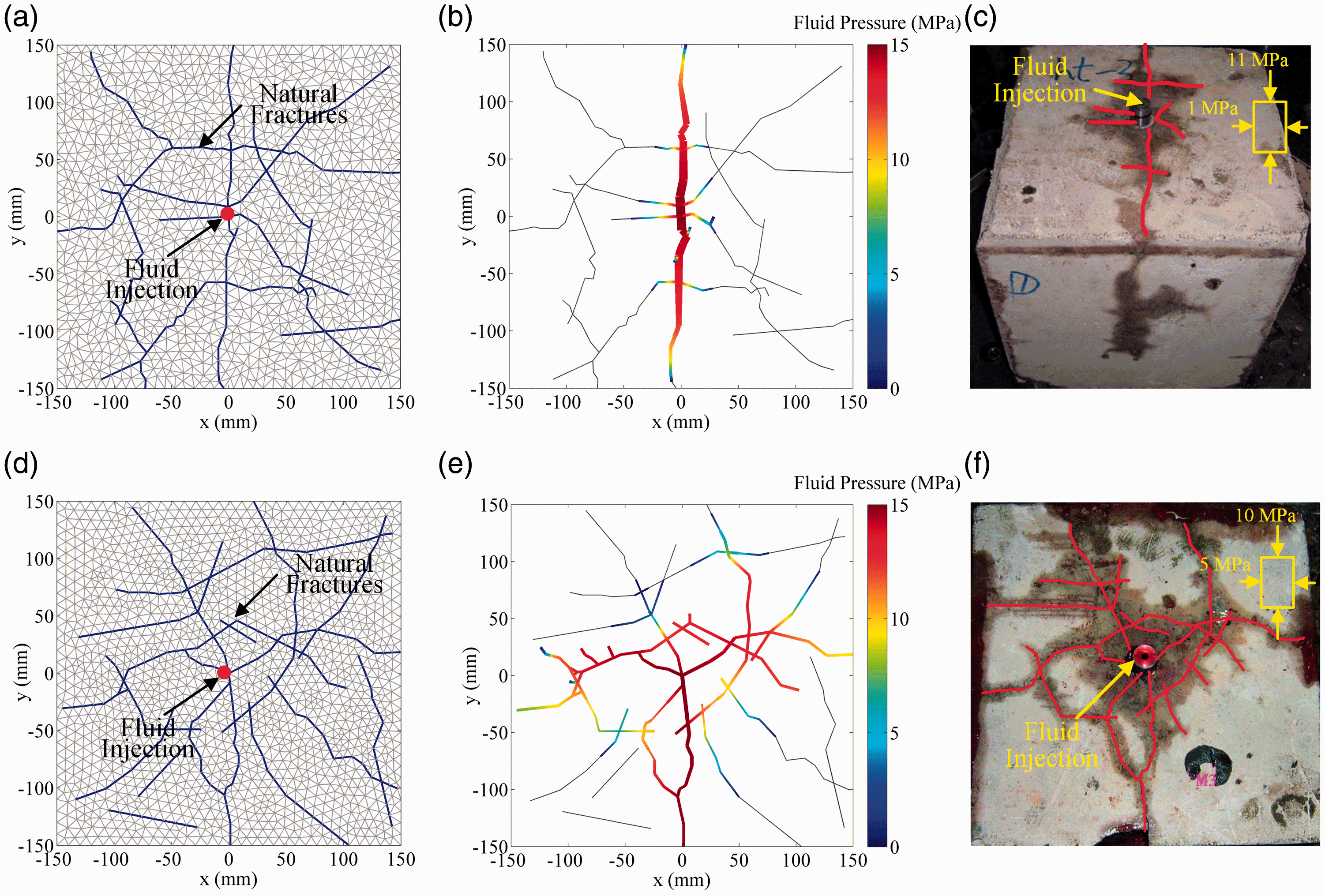
Comparison between numerical results obtained by this model and the experimental results of Zhou et al. (2010). (a) The numerical setting of case 1 (σ1-σ3 =10 MPa). (b) The numerical result of case 1. (c) The experimental result of case 1. (d) The numerical setting of case 2 (σ1-σ3 =5 MPa). (e) The numerical result of case 2. (f) The experimental result of case 2. In (b) and (e), the colored faces represent the stimulated HFs, while the gray faces represent the unaffected NFs. In (c) and (f), the stimulated fractures are marked by the red lines.
Hydraulic fracturing in naturally fractured shale reservoirs
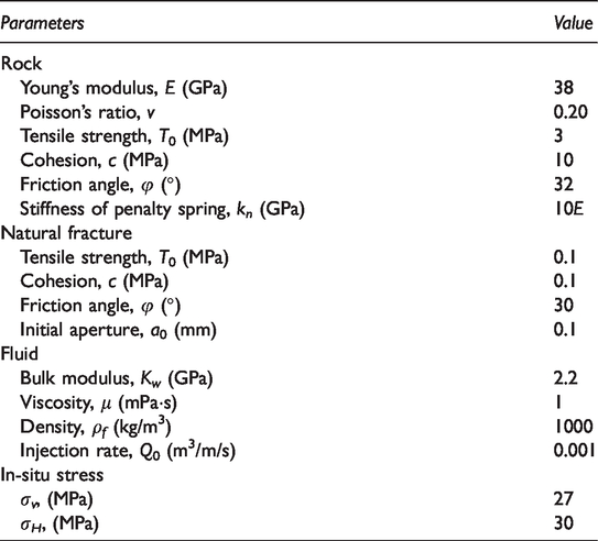
In this section, the proposed numerical model is used to simulate the evolution of complex HF networks in a naturally fractured shale reservoir. The setup of the basic model for simulations is based on the Silurian Longmaxi shale in the Sichuan Basin, which is now the most important gas-producing shale in China (Liu et al., 2013). The Longmaxi shale is characterized by a highly-developed NF system (Shen et al., 2018a; Wang et al., 2017; Xu et al., 2020). According to outcrop observations and core measurements, the NF networks in the Longmaxi shale reservoir mainly consist of bedding planes and high-angle fractures which are approximately perpendicular to the bedding planes (Fan et al., 2019). Figure 11(a) shows a Longmaxi shale outcrop in the Sichuan Basin, in which the bedding planes and high-angle fractures are clearly visible. It has been observed by microseismic monitoring that complex HF networks could be stimulated in the Longmaxi shale reservoir due to the existence of highly-developed NF networks (Liu et al., 2017). To simulate hydraulic fracturing in the Longmaxi shale reservoir, a 2D simplified geological model is developed according to the characteristics of the Longmaxi shale (Figure 11(b)). The dimensions of this model are 100 m × 100 m. To construct the complex NF system of the Longmaxi shale reservoir, bedding planes and high-angle fractures are both considered. The bedding planes are represented by a set of continuous NFs with a uniform spacing of 5 m. Since the deep-buried shale formation is mostly inclined, a dip angle of 30° is assigned to the bedding planes. In addition, the DFN model is employed to generate randomly distributed high-angle fractures. The minimum and maximum trace lengths of high-angle fractures are set to 5 m and 35 m, respectively, while the average trace length is set to 15 m. A minimum fracturing spacing of 2 m is also set because overly close NFs may greatly increase the amounts of block elements. Moreover, it is assumed that the generated high-angle fractures are all perpendicular to the bedding planes. In this way, the NF system is established. Then, this model is meshed by triangular blocks (Figure 11(c)). It is shown that the mesh quality is good, and the configuration of the NF network is well maintained. Then, the hydraulic fracturing process could be simulated. The fluid is injected in the center of the model at a constant rate. The input parameters used for simulations are listed in Table 1, in which the rock mechanical parameters of Longmaxi shale are based on the laboratory testing results by Heng et al. (2015) and Wu et al. (2016). The fracture parameters of the bedding planes and high-angle fractures are set be equivalent. In addition, the vertical stress σv is set to 27 MPa, and the horizontal stress σH is set to be slightly larger than σv (σH = 30 MPa) since the maximum principal stress of deep-buried shale reservoirs is typically in the horizontal plane. The results simulated by the proposed model are shown in Figure 12.
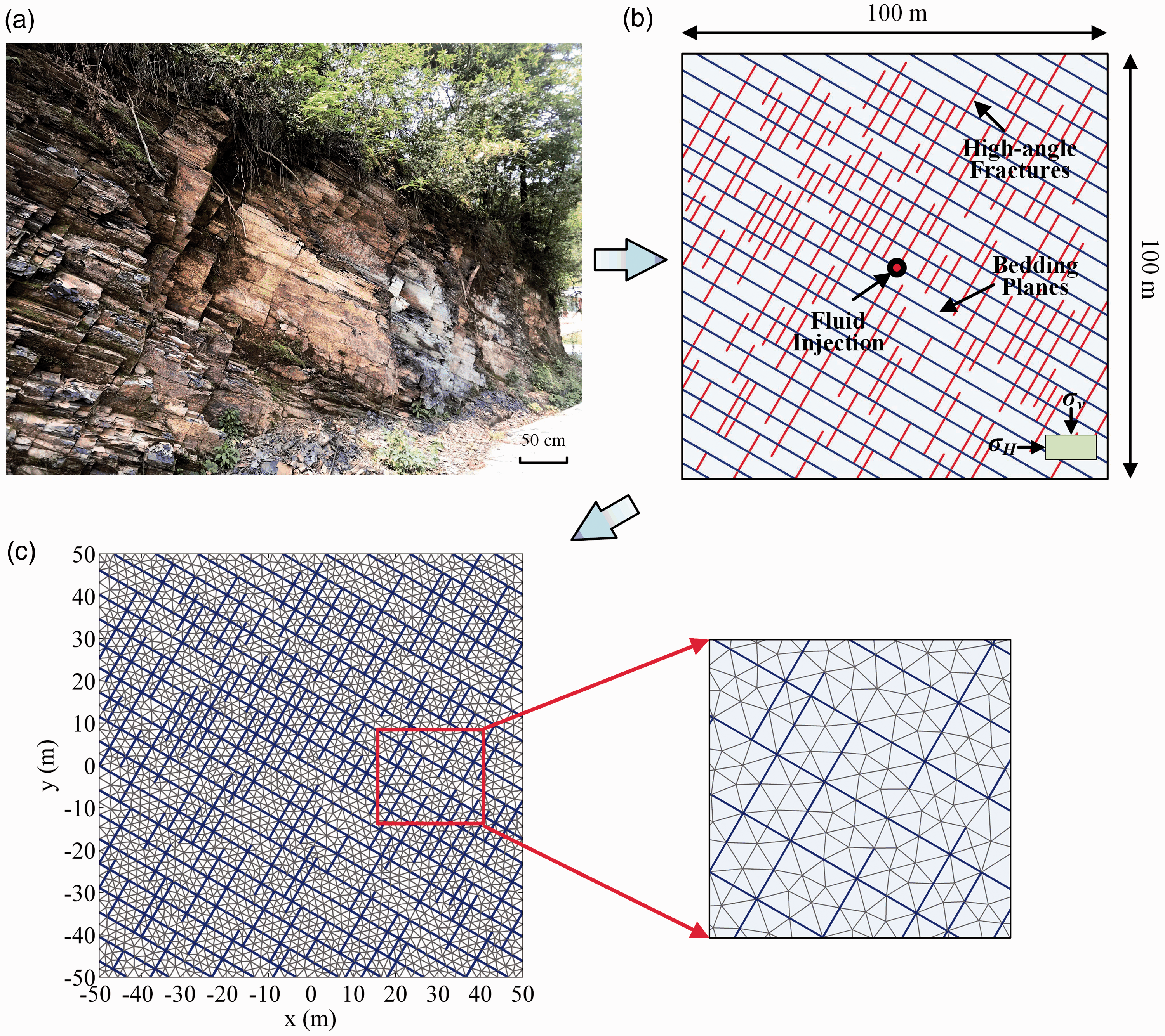
Model setup of a naturally fractured shale reservoir. (a) The outcrop of the Silurian Longmaxi shale located in the Sichuan Basin, China; the highly developed NF system consisting of bedding planes and high-angle NFs is visible. (b) 2 D simplified geological model of the naturally fractured Longmaxi shale reservoir. (c) Model mesh.
Input parameters for simulating hydraulic fracturing in the naturally fractured shale reservoir.
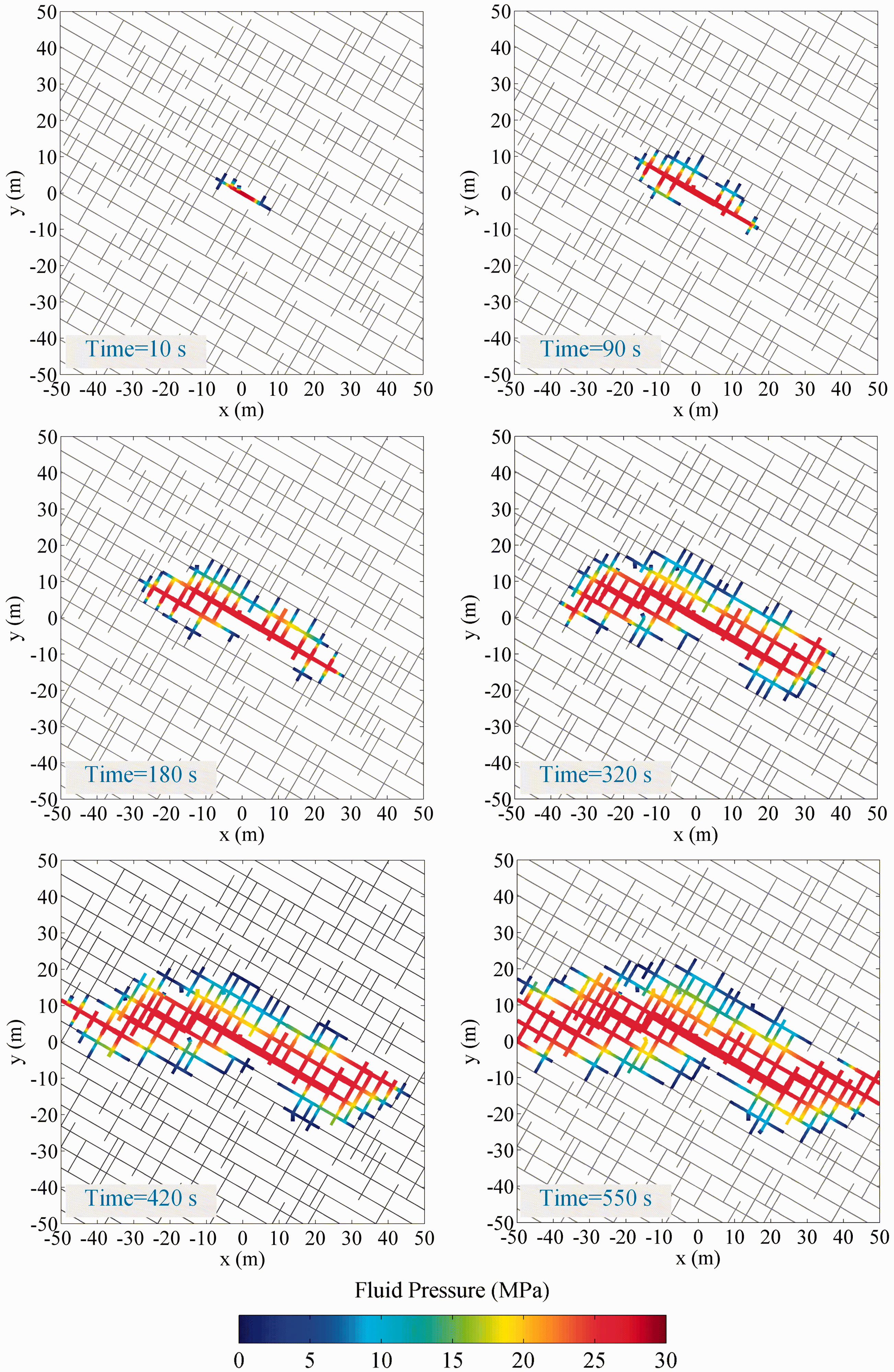
Evolution process of the fracture network and fluid pressure. The stimulated HFs and unaffected NFs are represented by colored lines and gray lines, respectively.
As highlighted in the sequence of illustrations in Figure 12, HFs tend to initiate from the injection point and propagate along the direction of maximum principal stress. In the early stage of fracturing, the HF mainly propagates along the bedding plane adjacent to the injection point. Then, due to the strong effect of in-situ stress, the main fracture turns toward the direction of maximum in-situ stress, and the connected high-angle fractures are opened. Since the high-angle fractures are well connected with several bedding planes, more bedding planes are then invaded by fluid, and more high-angle fractures connected to the activated bedding planes are opened. With time, more and more NFs are activated, and the HF network becomes very complex. It can be concluded from the above results that in-situ stress and the NF network both have significant effects on the formation of HF networks. The maximum principal stress controls the direction of HF network propagation, while the NF network determines the complexity and details of the fracture network configurations. It can be found in this example that almost all of the stimulated HFs are activated pre-existing fractures. In other words, when the shale reservoir is highly fractured, the HFs tend to propagate along pre-existing fractures rather than traverse the rock matrix. The main reasons are that the NF networks of the established model are very dense and well connected, and the in-situ stress difference used in this example is relatively small. This phenomenon is also consistent with the experimental results by Ma et al. (2017) and the field monitoring results by Liu et al. (2017). The highly connected NF network leads to a relatively large stimulated volume of reservoir despite the relatively small amount of intact rock fracturing. Thus, it is apparent that the production in the Longmaxi shale greatly benefits from the numerous NFs in the reservoir.
From a qualitative point of view, the above results show that the proposed simulation approach can capture the evolution process of complex HF networks, including fracture reorientation and interaction of HFs with NFs, which are typically neglected in most conventional numerical models based on highly idealized continuous rock mass representations. These phenomena are recognized to play a dominant controlling role in the hydraulic stimulation of shale gas reservoirs (Lisjak et al., 2017).
Discussion and conclusions
In this paper, a fully coupled hydromechanical model for simulating complex HF networks is developed based on DDA. Compared with several previous DDA-based fracturing models, the proposed model in this work realizes the simulation of complex HF networks. Comprehensive verification examples were given to verify the reliability of the model in simulating hydraulic fracturing. The first example was to check the correctness of the model in calculating the HF aperture. The second example was to verify the ability to predict the hydraulic pressure distribution in a single fracture. The third example was to check whether the model can accurately simulate the propagation of a single HF by comparison with the classical KGD fracture model. The last example was used to verify the ability to simulate complex HF networks by comparison with experimental results. All simulation results obtained by the proposed numerical model agree well with the analytical or experimental results, indicating that the proposed hydromechanical model can capture the main features of the hydraulic fracturing process. Then, the proposed model was used to simulate hydraulic fracturing in a naturally fractured shale reservoir. The modeling results show that the evolution process of complex HF networks can be captured by this model. This work indicates that DDA has great potential for studying hydraulic fracturing problems, especially for investigating the complex HF networks in highly fractured formations.
Compared with other commonly used numerical approaches for hydraulic fracturing, the DDA-based simulation tool described in this paper offers several advantages. The main advantage is the ability to consider arbitrary NF networks that are typically neglected in industry-standard and continuum-based approaches. A large number of fractures simultaneously propagating, branching and interacting can be simulated without encountering mathematical problems. Thus, this approach can be used for unconventional hydrocarbon reservoirs where natural discontinuities have significant effects on the hydraulic fracturing process. Second, since the formulation of DDA is parallel to that of the FEM, this approach shows better efficiency and stability in solving the static rock mass deformation induced by fluid pressure than conventional DEM approaches.
There are also some limitations in this DDA-based coupled model. First, the model is developed based on the assumption that the rock matrix is impermeable. Although the leak-off effect could be considered in the model, the resulting change in pore pressure in the surrounding media is not considered, which may significantly influence the pressure distribution within fractures. The second limitation is that the proposed model remains computationally expensive; thus, the number of block elements cannot be too large. This may impede further large-scale applications. Third, since the development of applicable 3D DDA codes remains far behind that of conventional DEM approaches, this work only presents a 2D model, which cannot capture the 3D nature of HF networks. Therefore, to overcome these limitations and use the DDA-based model for practical applications, our future work includes (i) implementing porous media flow into this DDA-based model; (ii) optimizing the structure of DDA and using the parallel computing technique to improve the computational efficiency; and (iii) extending the model to 3D.
Footnotes
Declaration of conflicting interests
The author(s) declared no potential conflicts of interest with respect to the research, authorship, and/or publication of this article.
Funding
The author(s) disclosed receipt of the following financial support for the research, authorship, and/or publication of this article: This work was supported by the Second Tibetan Plateau Scientific Expedition and Research Program (STEP) (No. 2019QZKK0904), the National Natural Science Foundation of China (No. 51734009), the Strategic Priority Research Program of the Chinese Academy of Sciences (No. XDB10030000), the Science Foundation of Key Laboratory of Shale Gas and Geoengineering, Institute of Geology and Geophysics, Chinese Academy of Sciences (No. KLSG201708), the Key Research Program of the Institute of Geology & Geophysics, CAS (No. IGGCAS-201903), and the Joint PhD Training Program of University of Chinese Academy of Sciences (UCAS).