
Abstract
Revealing the space-time evolution characteristics of overlying strata deformation and failure is the key for safe and efficient mining of steeply dipping coal seam. In this paper, based on the physical similarity simulation experiment and field measurement method, the non-uniform filling characteristics of gangue in gob and the roof migration law are comprehensively determined, the evolution characteristics and distribution patterns of the abutment pressure in the upper and lower sections, the distribution characteristics of the working resistance of the support, and the regional strata behavior law in the mining process are analyzed, and the technical measures for the stability control of the support in steeply dipping coal seam are put forward. Results shown: With the advancing distance increases, the accumulation range of gangue increases, and the inverted triangle airspace begins to appear repeatedly in the gob behind the support. In the deep gob, the angle between the gangue pile and the horizontal plane decreases continuously from the lower part to the upper part along the inclined direction. Horizontal displacement, vertical displacement and combined displacement of roof show an evolutionary trend of ‘increase – stability’. The peak displacement position moves from the upper part to the middle part of the working face, which is located at the hinge point between the broken block and the failure envelope surface. The evolution of abutment pressure of headgate and tailgate T-junction shows a trend of ‘increase – stability’. The peak and concentration coefficient at headgate T-junction are greater than tailgate T-junction. The load imbalance characteristics of the support in working face are obvious, and the basic characteristics along the inclined direction are the largest in the middle area, the second in the upper and the smallest in the lower area. The initial force and working resistance of support should be improved, and the position of the support should be adjusted in time in practical engineering. The results provide reference and guidance for practical production.
Keywords
Introduction
The steeply dipping coal seam refers to the coal seam with angle of 35°–55°, which is recognized as a difficult coal seam around world. Steeply dipping coal seams are widely distributed in major mining areas in China, with reserves of 180 ∼ 360 billion tons and production of 150 ∼ 300 million tons, accounting for 10 ∼ 20% and 5 ∼ 8% of China's coal reserves and production, respectively. More than 50% of steeply dipping coal seams are high-quality coking coal and anthracite (e.g., Wu et al., 2013, 2020).
Affected by seam angle, there are significant differences in strata behavior, strata migration law and support-surrounding rock relationship between steeply dipping coal seam and horizontal coal seam. Over the past three decades, a large number of scholars have studied from different aspects of longwall fully mechanized mining in steeply dipping medium thick coal seam, longwall fully mechanized caving mining in thick coal seam, and coal seam group mining under different mining methods of strata behavior(e.g., Luo et al., 2021; Sun et al., 2019; Wang et al., 2020; Yang et al., 2021), bearing capacity of gangue(e.g., Ding et al., 2022; Lv et al., 2022; Wei et al., 2021), space-time evolution characteristics of mining transfer paths(e.g., Chi et al., 2020; Luo et al., 2022a, 2022b, 2022c), disaster-causing mechanism of irregular random separation in stope space(e.g., Hu et al., 2020; Wu et al., 2021), surface subsidence(e.g., Huang et al., 2020; Yin et al., 2018), coupling mechanism and stability control of support-surrounding rock system under interaction of roof and floor(e.g., Liu, 2021; Shen et al., 2021; Wang and Jiao, 2016; Wang et al., 2018; Xie et al., 2021), mechanism of support and equipment downturn and surrounding rock disaster(e.g., Luo et al., 2018, 2022a, 2022b, 2022c). The existing research has solved the basic problems of safe and efficient mining of steeply dipping coal seam to a certain extent. However, it is very regrettable that there is no fully mechanized / caving face with an annual output of millions of tons in steeply dipping coal seams. The fundamental reason is that the roof deformation presents typical regional characteristics. When the motion strata of the roof changes, the interaction between the roof -support- floor also changes. The support is easy to produce no-load and partial load. The rotation, sliding and inter squeezing of the support occur frequently. In serious cases, the paralysis of the support system in the working face caused by the instability of the local support is easy to induce large area of surrounding rock disaster, resulting in a large number of casualties and economic losses. The existing research methods mostly use plane model to study the characteristics of roof deformation and failure in steeply dipping coal seam mining. It is considered that in steeply dipping coal seam mining, the caving gangue tends to slide along the working face, and the working face tends to show the non-uniform filling characteristics of lower filling, middle half-filling and upper empty (e.g., Xie et al., 2018, 2020, 2021; Yin et al., 2018).
In the process of research, the author found that in the mining of steeply dipping coal seam, an inverted triangle airspace would be formed behind the support. Compared with the deep gob, the gangue filling characteristics of the gob behind the support had more obvious influence on the disaster of surrounding rock of the working face and the stability control of the support. In this paper, based on the physical similarity simulation experiment and field measurement method, the non-uniform filling characteristics of gangue in gob and the roof migration law are comprehensively determined, the evolution characteristics and distribution patterns of the abutment pressure in the upper and lower sections, the distribution characteristics of the working resistance of the support, and the regional strata behavior law in the mining process of the longwall working face are analyzed, and the technical measures for the stability control of the support in steeply dipping coal seam are put forward.
Engineering background
The 2130 coal mine of Xinjiang Coking Coal (Group) Co., Ltd is located in the western part of the Ewirgol mining area, 130 km north of Urumqi City and 120 km east of Tokson County. The designed industrial reserves of the mine are 8.851 million tons, and the recoverable reserves are 6.847 million tons. The mine field has a strike length of 7 km, a north-south width of 1.5 km, and a mine field area of about 10.5 km2. The mine adopts the longwall fully mechanized mining, with a designed production capacity of 0.9 million t/year and a service life of 70 years. The geographical location of the mining area is shown in Figure 1.
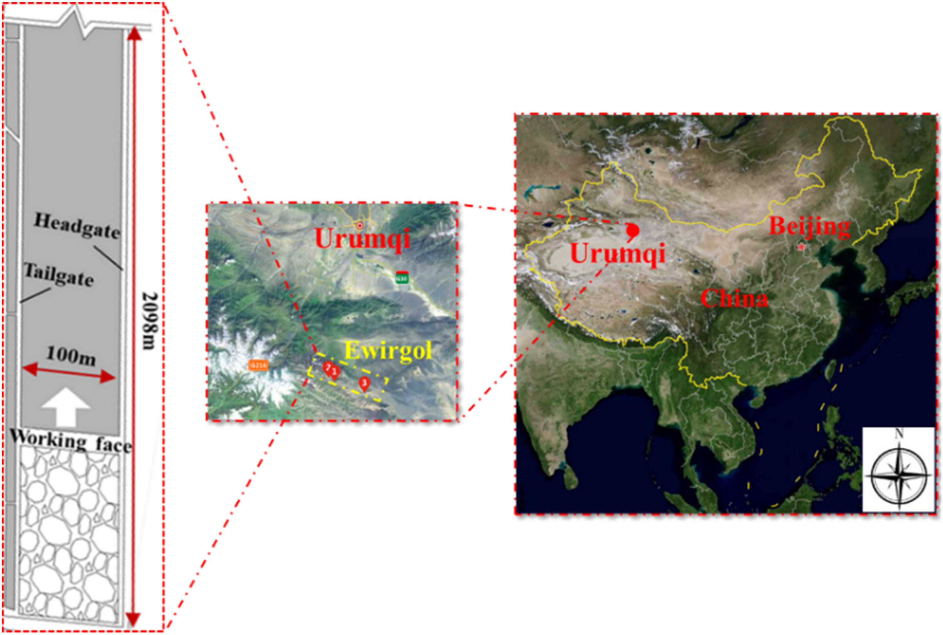
Location of mining area.
25,221 Working face is located in district 2 of the #5 coal seam. The mining elevation is +2047–2120 m, the strike length is 2098 m, and the inclined length is 100 m. The angle fluctuates within 36°–46° with an average of 45°. The coal bulk density is 1.35 t/m3. The seam is stable with a thickness of 3.58–9.77 m and average thickness of 5.77 m. The hardness coefficient f of the coal is 0.3–0.5.
Model test
Design of test
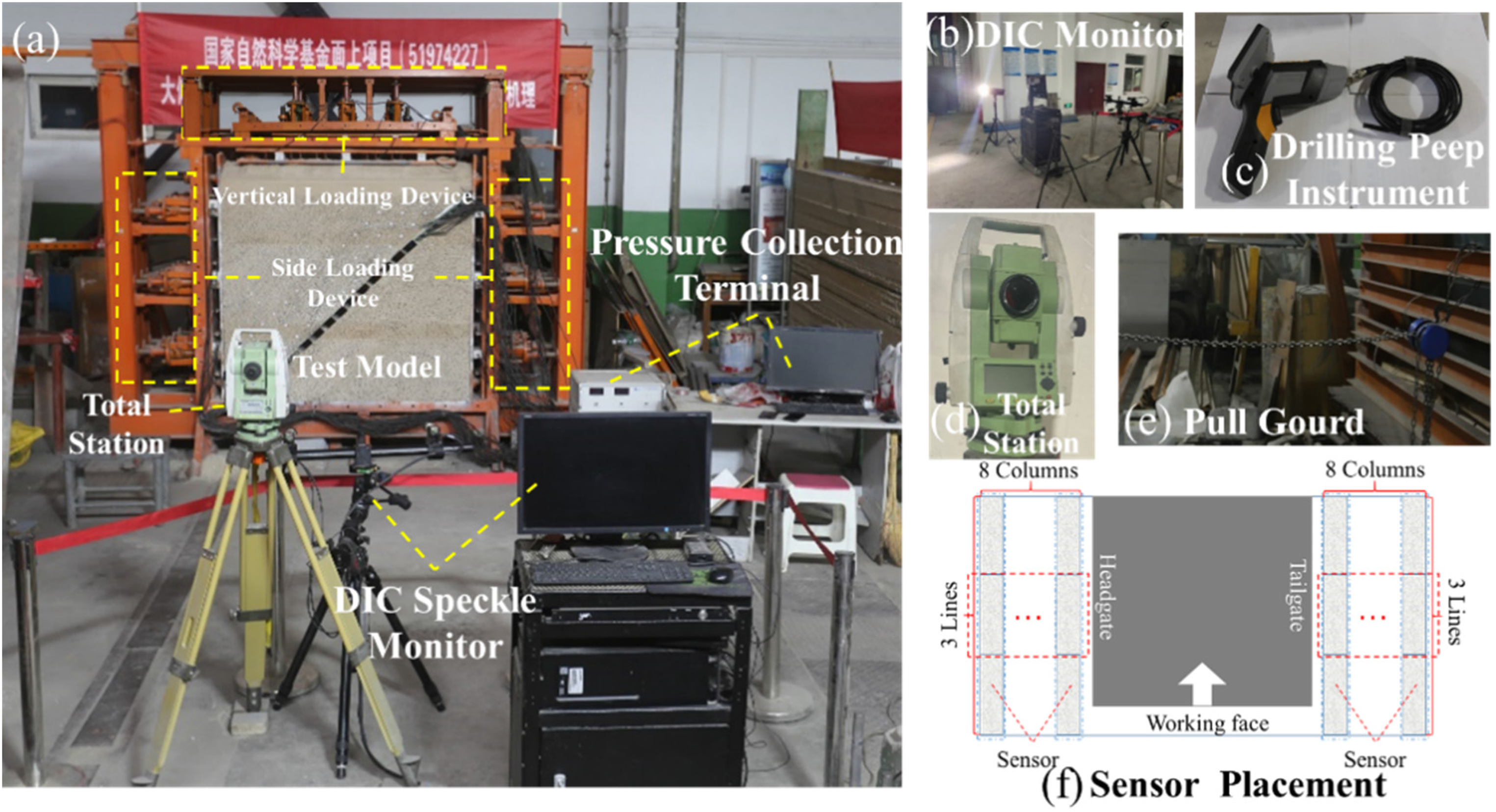
To understand space-time evolution laws of roof deformation and failure and non-uniform filling characteristics of gangue during the mining process of steeply dipping coal seams, a 1500 mm × 1500 mm × 600 mm model frame independently designed and developed by Xi’an University of Science and Technology was selected. The biggest difference between the model frame and the plane model is that: First, load constraints can be applied in both horizontal and vertical directions, which is more suitable for the stress conditions in the actual mining process. Second, it can advance a certain distance along the working face, which reflects the spatial and temporal evolution characteristics of surrounding rock deformation and failure to a certain extent. During the mining process, monitoring methods such as drilling peep instruments and pressure sensors were used to quantitatively characterize the deformation and failure of surrounding rock and the evolution characteristics of abutment pressure of steeply dipping coal seams. According to the physical and mechanical characteristics of coal and rock, sand and coal ash are selected as aggregate, gypsum and white powder are used as adhesive materials, and 8 ∼ 20 mesh mica powder is used as layered material. The physical and mechanical parameters of the model and their matching are shown in Table 1. According to the model size, the geometric similarity condition is determined as C l = 1:100. Other similarity constants are solved as follows (p represents the prototype, m represents the model):
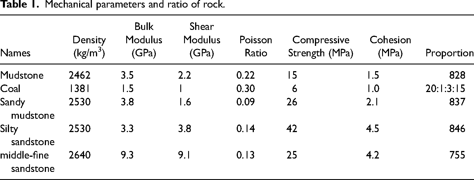
Mechanical parameters and ratio of rock.
Similar parameter of density:
Similar parameter of stress:
Similar parameter of load:
Similar parameter of time:
Equipment and plans
During the experiment, the hydraulic jack was used to compensate the vertical load of 0.6 MPa at the top of the model, and the hydraulic jack was used to compensate the horizontal stress of 0.3 MPa on the left and right sides of the model, and the displacement constraint was used at the bottom of the model. the prefabricated rectangular square steel (length × width × height = 600 × 100 × 50 mm) is pulled out by pressure gourd on the back of the model to simulate the working face advancing, and the advance distance is 2 cm / time. And the upper and lower section coal pillars are set to 50 cm. Three rows of displacement measuring points are arranged on the model surface along the inclined direction, numbered a–c, and the spacing of measuring points is 10 cm, and the row spacing is 10 cm. DIC digital speckle technique is used to measure the displacement variation of the model surface during micro deformation and failure. The instrument accuracy is 10−6 m. The drilling peep instrument was used to record the gangue pile structure inside the model during mining. PENTAXR-400NX total station is used to monitor the displacement and the accuracy is 10−3 m. At the upper and lower sections of the model, three lines and eight columns of CL-YB-137 C pressure sensors were arranged along the strike and inclination respectively. The length, width and height of the sensor were 20, 4 and 5 cm respectively, which were consistent with the thickness of the coal seam. The distribution characteristics of the abutment pressure of the surrounding rock of the working face were monitored in real time. Digital camera was used to record the failure of strata. The model and equipment layout are shown in Figure 2.
Test model.
Results
Space-time evolution characteristics of strata migration
The experimental results were as follows:
When the working face advances 10 cm, the roof breaks as shown in the red curve in Figure 3(a). The hanging length of the immediate roof is 77.5 cm, the caving height is 7 cm from floor, and the upper end tends to break the residual ladder length 4.5 cm. The gangue slips downward under the action of gravity field and fills the lower part of the inclination. The length of the ‘touching area’ is 18 cm, the length of the ‘non-touching area’ is 26 cm, and the length of the hallow surface is 56 cm. When the working face advances 15 cm, the main roof collapses. The caving gangue fills the gob further, and the filling range increases along the inclined direction. The main roof hanging length is 72 cm, and the caving height is 10 cm from floor. The collapse of the main roof intensifies the damage degree of the surrounding rock, and the roof broken residual ladder length is 3.8 cm at tailgate T-junction. The depth of broken residual structure generated at the tailgate T-junction is 10 cm, and the length of low immediate roof inclination is 5 cm. The filling of gangue in the middle and lower parts of the inclination is dense, the height of gangue accumulation is 9.5 cm, and the filling length is 90 cm. In the middle and upper part of the inclined, there is an inverted triangle surface in the gob behind the support, which with the angle length of 16.5 cm and the oblique edge length of 20 cm. The accumulation range of gangue on the floor extends further along the strike. The inverted triangle airspace is formed by the inverted triangle surface and the cavity area, as shown in Figure 3(b). When the working face advances 40 cm, the filling of gangue from upper to end along the inclined direction in deep gob shows the characteristics of dense to loose. The size of gangue block in the lower part of the inclination is graded with each other, and the filling is dense with a certain strength. The block is mainly presented as a pile structure, which is called a full-filled area. In the middle part of the inclination, the size of gangue is large, the filling is loose and the strength is low. This area is called complete-filled area. In the upper part of the inclination, the block presents an anti-masonry structure, and there is a cavity at the tailgate T-junction. This part is called partial-filled area, as shown in Figure 3(c). In the full-filled area, the angle between the gangue pile and the horizontal plane is 40°. In the complete-filled area, the gangue pile reaches the highest point and forms a repose surface under the action of gravity. Therefore, the angle between the gangue pile and the horizontal plane gradually decreases, with an angle of 37° in the middle and lower regions and 20° in the middle and upper regions. In the partial-filled area, there is an anti-masonry structure in the inclined upper gangue. One end of the caving roof is overlapped at the residual wall of the broken roof, and the other end is overlapped on the gangue accumulation body. The angle between the anti-masonry structure and the horizontal plane is 96°. In the gob behind the support, the gangue along the strike presents a hinged pile structure with the masonry lengths of 4.8 and 4.5 cm, respectively, as shown in Figure 3(c). When the working face advances 60 cm, the inverted triangle face begins to appear repeatedly in the gob behind the support. In deep gob, gangue pile is still mainly divided into full, complete and partial-filled areas. With the increase of caving height, the amount of gangue further increases. The hanging length of main roof is 40 cm, and the caving height is 16.5 cm from the floor. The filling range of gangue in deep gob is 95.5 cm along the inclined distance. In the full-filled area, complete-filled area and partial-filled area, the angle between the gangue pile and the horizontal line are 40°, 35°, 25°, respectively. The angle between the anti-masonry structure and the horizontal plane in this area is 97°. The length of the curved triangular plate generated within the roof of the gob is 40.5 cm along the strike and 19 cm along the inclined direction. The length of the right-angle side and the oblique side of the gob free face behind the support is 25.8 and 39.7 cm, respectively, as shown in Figure 3(d).
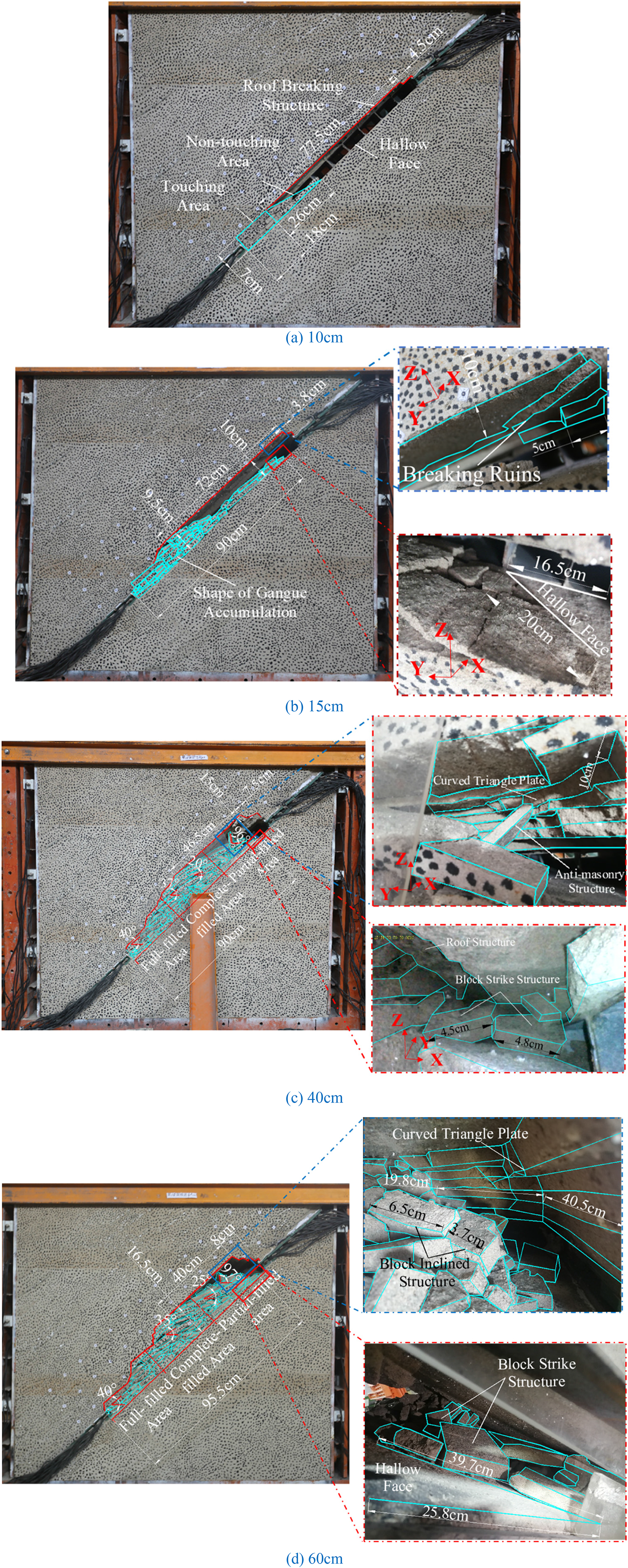
Characteristics of strata migration. (a) 10 cm, (b) 15 cm, (c) 40 cm, (d) 60 cm.
It can be seen that the non-uniform filling of caving gangue in gob is an obvious feature of steeply dipping coal seam mining different from horizontal coal seam. At the early stage of working face mining, the gangue slips downward under the action of gravity field after the immediate roof breaking, filling the lower part of the inclination. When the working face continues to move forward, the inverted triangle free face and the cavity area jointly constitute the ‘inverted triangle airspace’ in the gob behind the support. In order to quantitatively the space-time evolution characteristics of the deformation and failure of overburden, the DIC monitoring technology is further studied below.
DIC monitoring results
Digital Image Correlation (DIC) is an optical method based on non-contact image. Digital image is used to obtain the full-field displacement and strain response of the structure. It has been applied to rock mechanics tests (e.g., He et al., 2018; Pan et al., 2018). DIC uses the industrial camera to obtain the speckle image of the object surface, and then analyzes the image based on the algorithm to extract the deformation information of the three-dimensional coordinates, displacement and strain field of the measured structure surface. DIC obtains the displacement of the measurement point Pi (i = 1, 2, 3) by calculating the displacement difference of the center point of the sub-region before and after the image deformation, as shown in Figure 4.
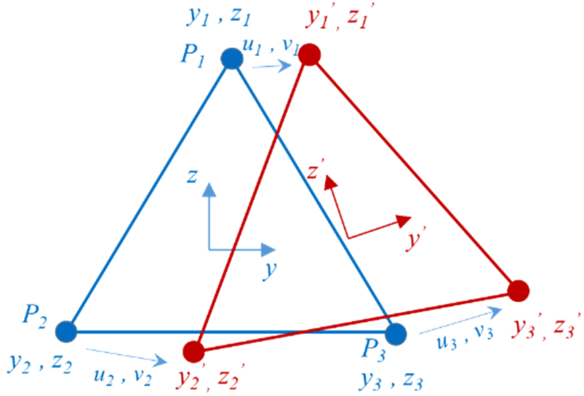
Principle of digital image correlation strain calculation.
DIC is essentially a derivation of displacement, and the change of measurement points in subspace can be represented by gradient matrix F (e.g., Su et al., 2018):

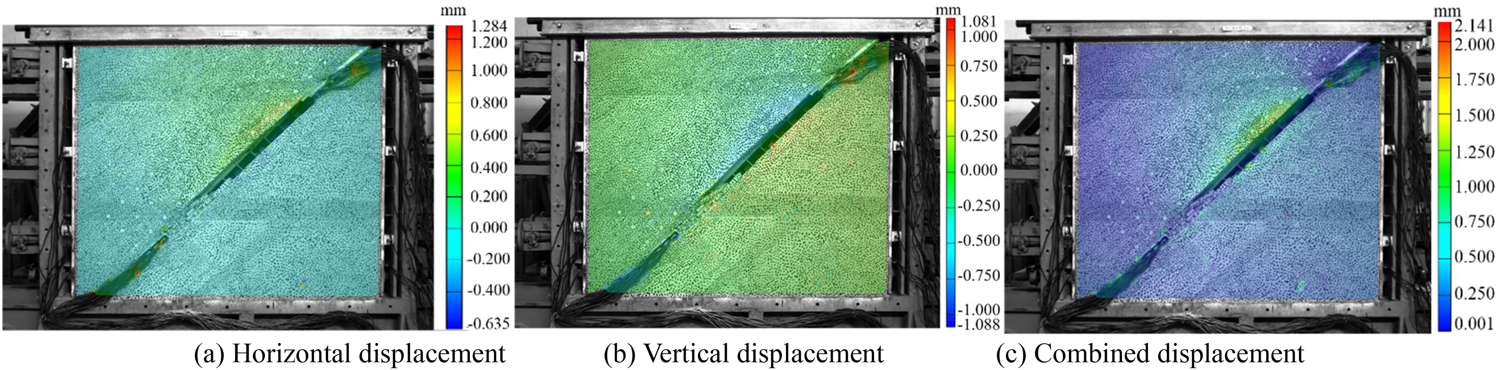
Displacement of surrounding rock with advancing 10 cm. (a) Horizontal displacement (b) Vertical displacement (c) Combined displacement.
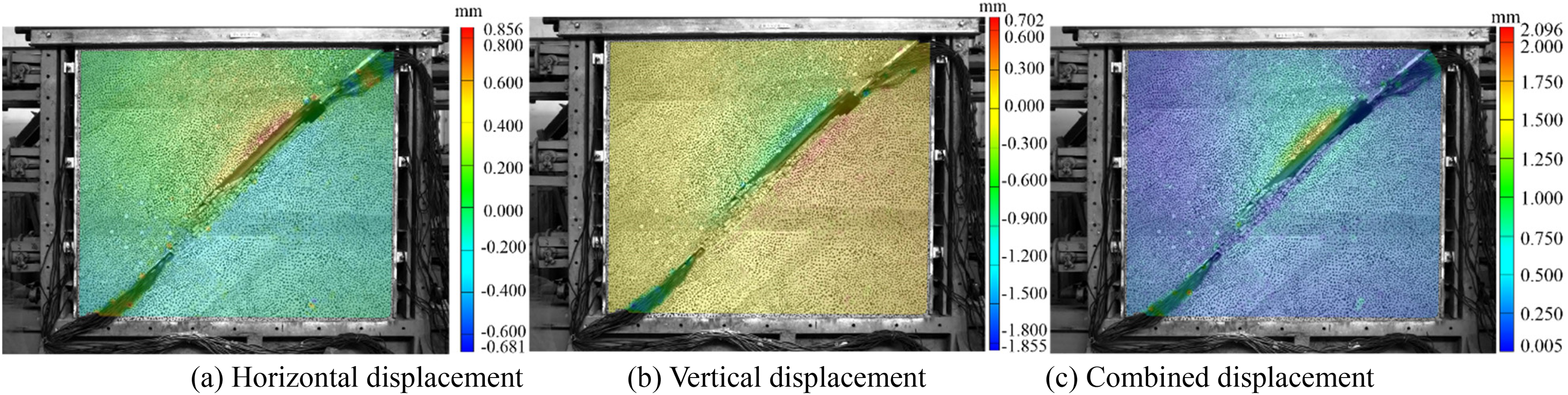
Displacement of surrounding rock with advancing 15 cm. (a) Horizontal displacement (b) Vertical displacement (c) Combined displacement.
Displacement of surrounding rock with advancing 45 cm. (a) Horizontal displacement (b) Vertical displacement (c) Combined displacement.
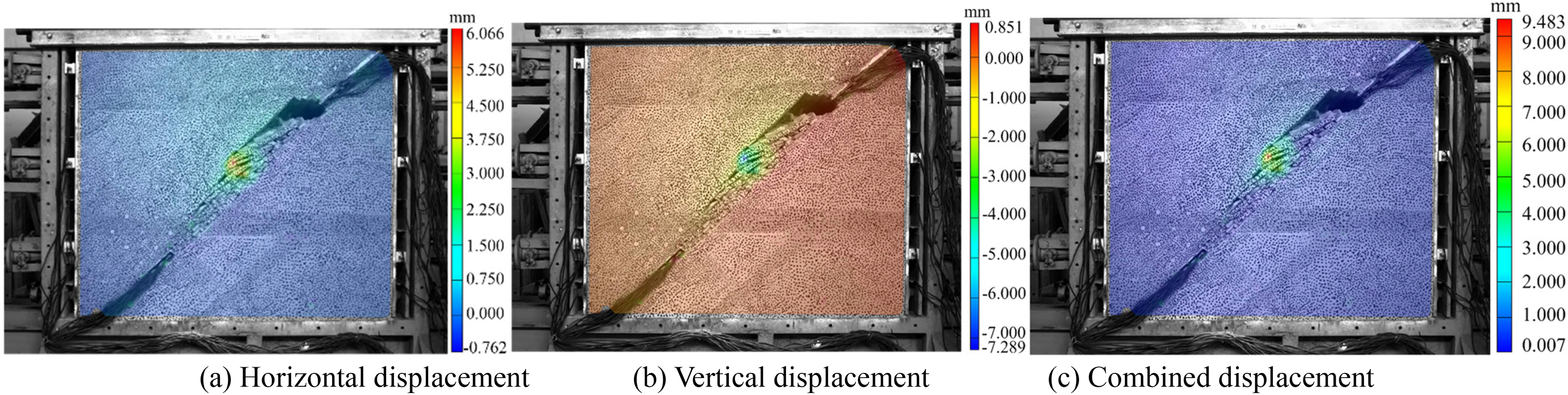
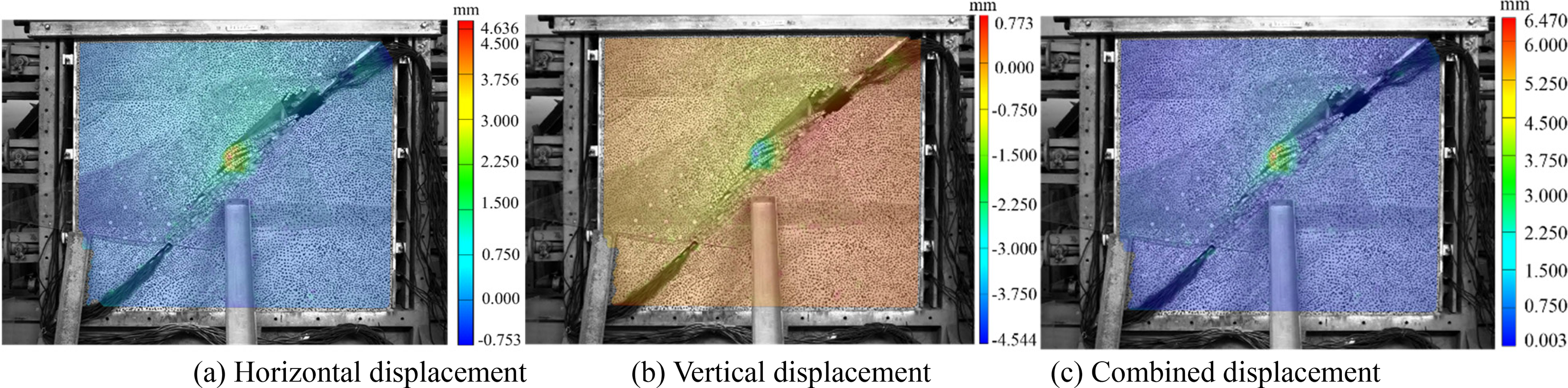
Displacement of surrounding rock with advancing 60 cm. (a) Horizontal displacement (b) Vertical displacement (c) Combined displacement.
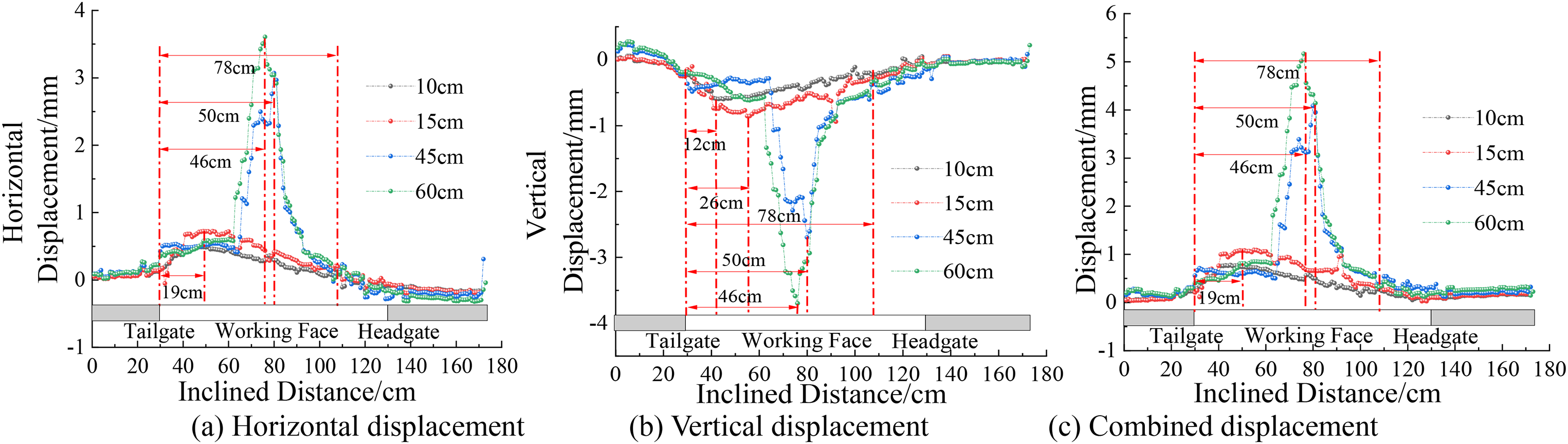
Displacement evolution law of surrounding rock. (a) Horizontal displacement (b) Vertical displacement (c) Combined displacement.
Figures 5–9 shows:
With the advancing, the horizontal, vertical and combined displacement of surrounding rock shows an increasing-stable evolution trend. The peak position moves from the upper part to the middle part of the working face, which is located at the hinge point between the broken rock and failure envelope surface. When the advancing distance are 10, 15, 40, 60 cm, the peak horizontal displacements are 0.44, 0.72, 3.07, 3.61 mm, the peak positions are 19, 19, 50, 46 cm from tailgate T-junction, the increase are 63.64%, 326.39%, 17.59%, respectively. The peak values of vertical displacement are −0.59, −0.79, −2.7, −3.7 mm, respectively. The peak positions are 12, 26, 50, 46 cm away from tailgate T-junction, and the increase are 33.9%, 241.77%, 37.04%, respectively. The peak values of combined displacements are 0.77, 1.08, 4.09, 5.17 mm, respectively. The peak positions are 19, 19, 50, 46 cm away from the tailgate T-junction, and the increase are 40.26%, 278.7%, 26.41%, respectively. When the advancing distance is small (10 cm, 15 cm), the horizontal, vertical and combined displacement of the roof is located in the upper part of the working face, and is within the range of 78 cm from tailgate T-junction. The lower area is affected by filling of gangue, and the deformation and failure of roof are small. With the increase of the advancing distance, the breaking degree of the overburden strata increases, and there is a cavity area in the upper part of the inclination. Inside the broken envelope surface of the roof, the phenomenon of gangue hinge is obvious, and the horizontal, vertical and combined displacements of the roof are large. Outside the broken envelope surface, the suspended roof tends to be the main bearing structure, and the roof deformation degree is smaller than that at the hinged position.
From the above analysis, it can be seen that the formation level of roof arch shell structure increases gradually from bottom to top along the inclined direction of working face, and the stability is also gradually weakened. The vault evolves to the high level, and the arch foot on both sides further shifts to both sides of the tailgate and headgate. The abutment pressure is selected as the quantitative eigenvalue of the evolution law of roof structure.
Evolution characteristics of abutment pressure of surrounding rock
Abutment pressure refers to the vertical pressure acting on coal seam, rock and gangue in the range of surrounding rock stress redistribution after mining, which is a quantitative representation of the internal stress transfer evolution of surrounding rock asymmetric bearing structure. The CL-YB-137C sensor embedded in the upper and lower sections of the working face is used to monitor the evolution characteristics of the abutment pressure of the working face in the process of advancing, as shown in Figures 10–13:
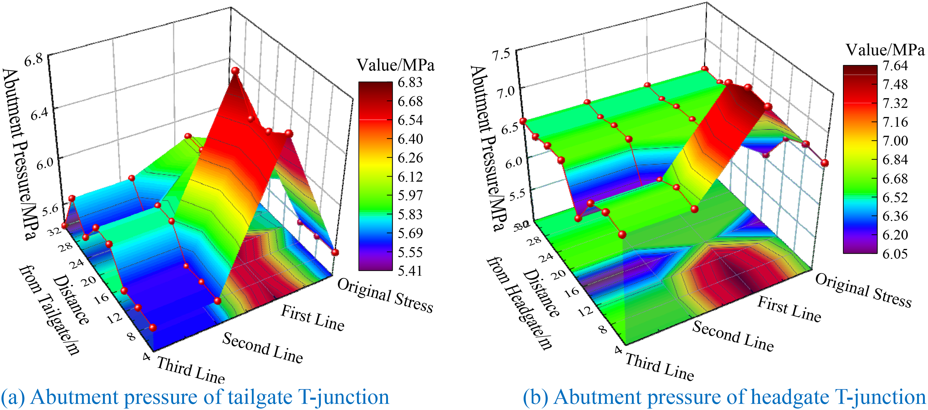
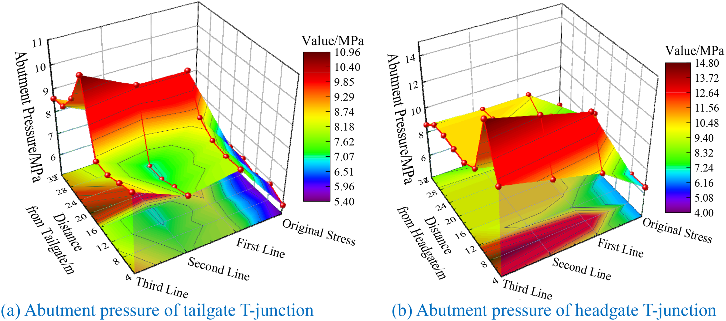
Abutment pressure of surrounding rock with advancing 10 cm. (a) Abutment pressure of tailgate T-junction (b) Abutment pressure of headgate T-junction.
Abutment pressure of surrounding rock with advancing 15 cm. (a) Abutment pressure of tailgate T-junction (b) Abutment pressure of headgate T-junction.
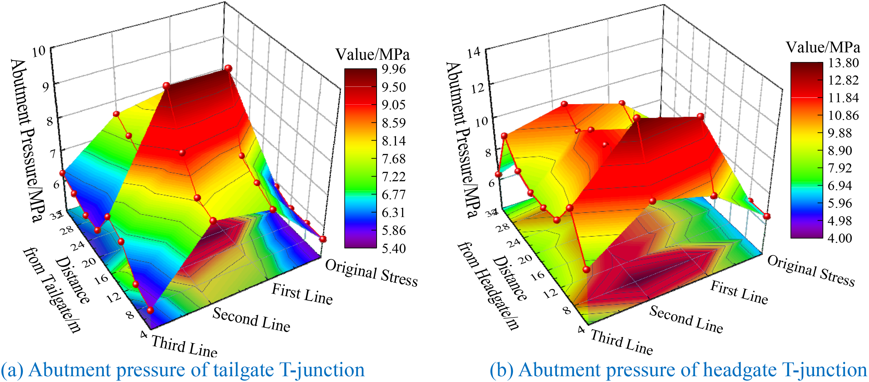
Abutment pressure of surrounding rock with advancing 40 cm. (a) Abutment pressure of tailgate T-junction (b) Abutment pressure of headgate T-junction.
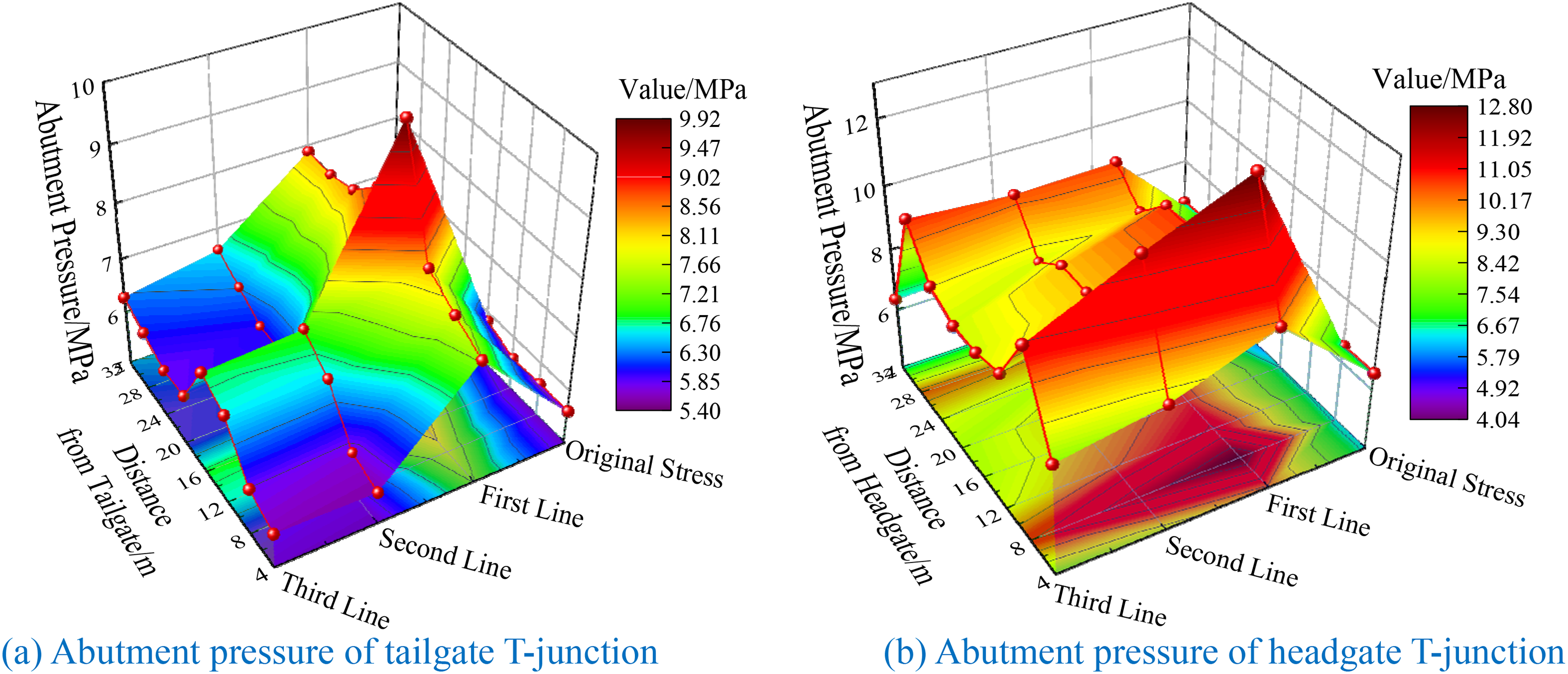
Abutment pressure of surrounding rock with advancing 60 cm. (a) Abutment pressure of tailgate T-junction (b) Abutment pressure of headgate T-junction.
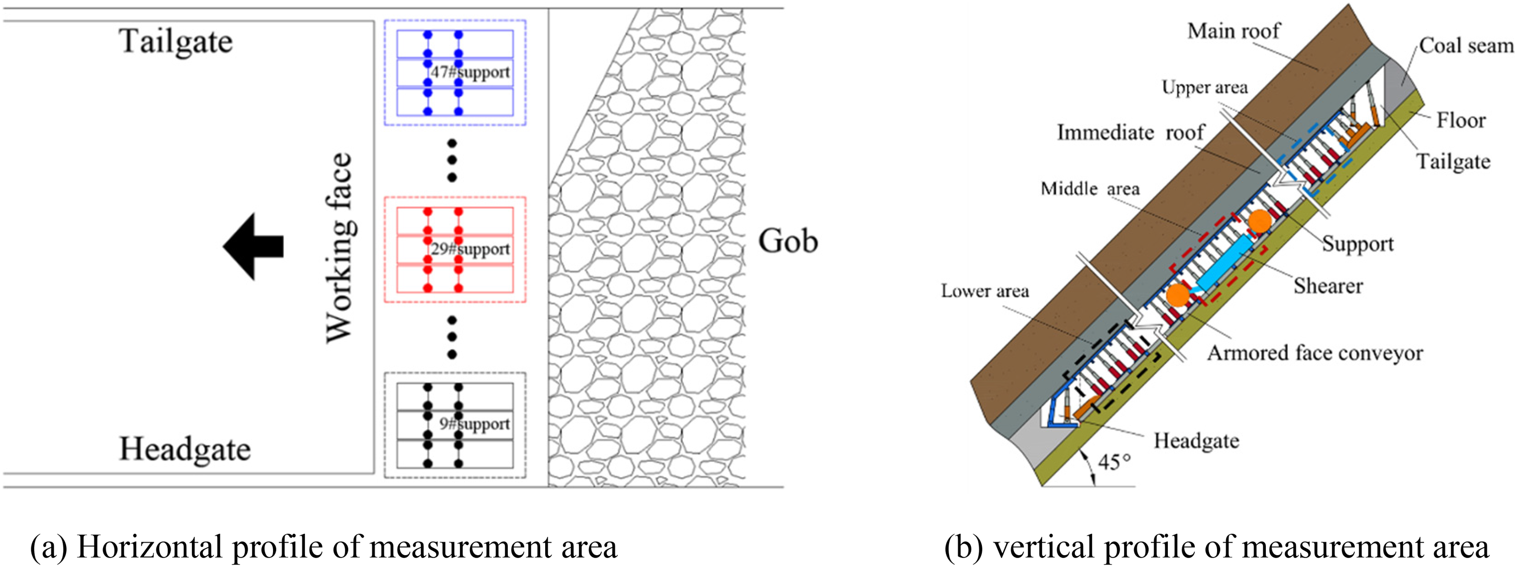
Layout of measurement area. (a) Horizontal profile of measurement area (b) vertical profile of measurement area.
Figures 10–13 shows:
The abutment pressure at the tailgate and headgate T-junction presents different evolution characteristics in the mining process of steeply dipping coal seam. The evolution of abutment pressure at the T-junction shows an ‘increase-stability’ trend. The peak value and concentration coefficient of abutment pressure at headgate T-junction are greater than those at tailgate T-junction. When the working face advances 10 cm, the abutment pressure on both sides of the working face increases slightly, and the abutment pressure at T-junction of the advanced working face is basically unchanged compared with the original stress. At the tailgate T-junction, the peak value of abutment pressure increases to 6.82 MPa, the concentration coefficient is 1.17, and the peak position is 16 cm away from the T-junction. At the headgate T-junction, the peak value of abutment pressure increases to 7.63 MPa, the concentration coefficient is 1.15, and the peak position is 8 cm away from the T-junction. When the working face advances 15 cm, the abutment pressure on both sides of the working face changed greatly. At the tailgate T-junction, the peak value of abutment pressure increases to 9.92 MPa, the concentration coefficient is 1.7, and the peak position is 16 cm away from the T-junction. At the headgate T-junction, the peak value of abutment pressure increases to 12.79 MPa, the concentration coefficient is 1.93, and the peak position is 8 cm away from the T-junction. When the working face advances 40 cm, mining effects spread to the second row of sensors. At the tailgate T-junction, the peak value of abutment pressure increases to 9.95 MPa, the concentration coefficient is 1.71, and the peak position is 16 cm away from the T-junction. At the headgate T-junction, the peak value of abutment pressure increases to 13.85 MPa, the concentration coefficient is 2.08, and the peak position is 8 cm away from the T-junction. When the working face advances 60 cm, mining effects spread to the third row of sensors. At the tailgate T-junction, the peak value of abutment pressure increases to 10.87 MPa, the concentration coefficient is 1.88, and the peak position is 16 cm away from the T-junction. At the headgate T-junction, the peak value of abutment pressure increases to 14.56 MPa, the concentration coefficient is 2.23, and the peak position is 8 cm away from the T-junction. In the process of working face advancing, the increments of the concentration coefficients of abutment pressure at tailgate T-junction are 45.3%, 0.5% and 9%, respectively. The increments of concentration coefficients of headgate T-junction are 67.83%, 7.77% and 7.21% respectively. After unloading failure of the rock strata inside the failure envelope surface, the undamaged rock strata with bearing capacity outside the failure envelope surface transfer the roof stress to the surrounding rock. The spatial structure of stope overburden strata has the asymmetry of geometric shape and the non-uniformity of stress distribution, which evolves and tends to be dynamic and steady in the process of working face advancing, which also reveals the mechanism of abutment pressure showing an ‘increase-stability’ evolution trend.
The movement of the roof under the action of its self-weight and overlying strata load is inevitable and active, while the load and behavior response of the support are passive. When the movement strata of the roof changes, the interaction relationship between the roof – support – floor also changes. Affected by the angle of seam, the working resistance of supports in different regions presents typical regional characteristics.
Field monitoring
Layout of measurement area
In order to lay the foundation for the safe and efficient production of the subsequent working face, the mine pressure observation for nearly four months was carried out at 25,221 working face of a mine in Xinjiang coking coal group, as shown in Figure 14. The mining processes at 25,221 working face adopt a fully mechanized large-height mining method with the following process flow: cutting coal downward → clearing floating coal upward→ pushing conveyor → moving support. According to the special geological conditions of the mine, the working resistance of the support was finally determined to be 6500 kN; to counter this, 60 ZZ6500/22/48 shield supports and 3 ZZG6500/22/48 transition supports were used. The mining pressure on the working face was observed with a KJ377 pressure dynamic system.
Monitoring method
The KJ377 mining pressure dynamic monitoring system was used to observe the mining pressure. The system is mainly composed of ground equipment (server, UPS, serial server) and underground equipment (communication substation, support pressure sensor, etc.), as shown in Figure 15. KJ377 can not only realize the computer dynamic simulation display detection parameters and alarms on the ground but also display data and alarms on site. And KJ377 system software can conduct specialized data analysis through mathematical models of rock pressure theory.

Layout diagram of mining pressure monitoring system.
Monitoring results
Field monitoring results are shown in Figure 16:
The average working resistance of the #9 support is 3505 kN, while the maximum working resistance during periodic weighting is 5400 kN, with a standard deviation of 767.12 kN, and the load distribution on the front and back legs of the support is more uniform, and the load on the front leg is larger than that on the back leg. The load ratios of the back to the front legs are 90.9%, 85.71%, and 90% before, during, and after the periodic weighting, respectively, and the average load ratio is 88.87%. The average working resistance and maximum working resistance during periodic weighting of the #29 support are 6422 and 9390 kN, respectively, with a standard deviation of 1358.17 kN. The load distribution on the front and back legs of the support is relatively uniform, and the load on the back leg is greater than that on the front leg. The load ratios of the back to the front legs are 105.15%, 108.57%, and 112.5% respectively, and the average load ratio is 108.74%. The average working resistance and maximum working resistance during periodic weighting of the #47 support are 4985 and 6481 kN, respectively, with a standard deviation of 1088.07 kN. And the load distribution on the front and back legs of the support is uneven, and the load on the back leg is much smaller than that on the front leg. The load ratios of the back to the front legs are 60.61%, 45.45%, and 47.62% respectively, and the average load ratio is 51.23%.
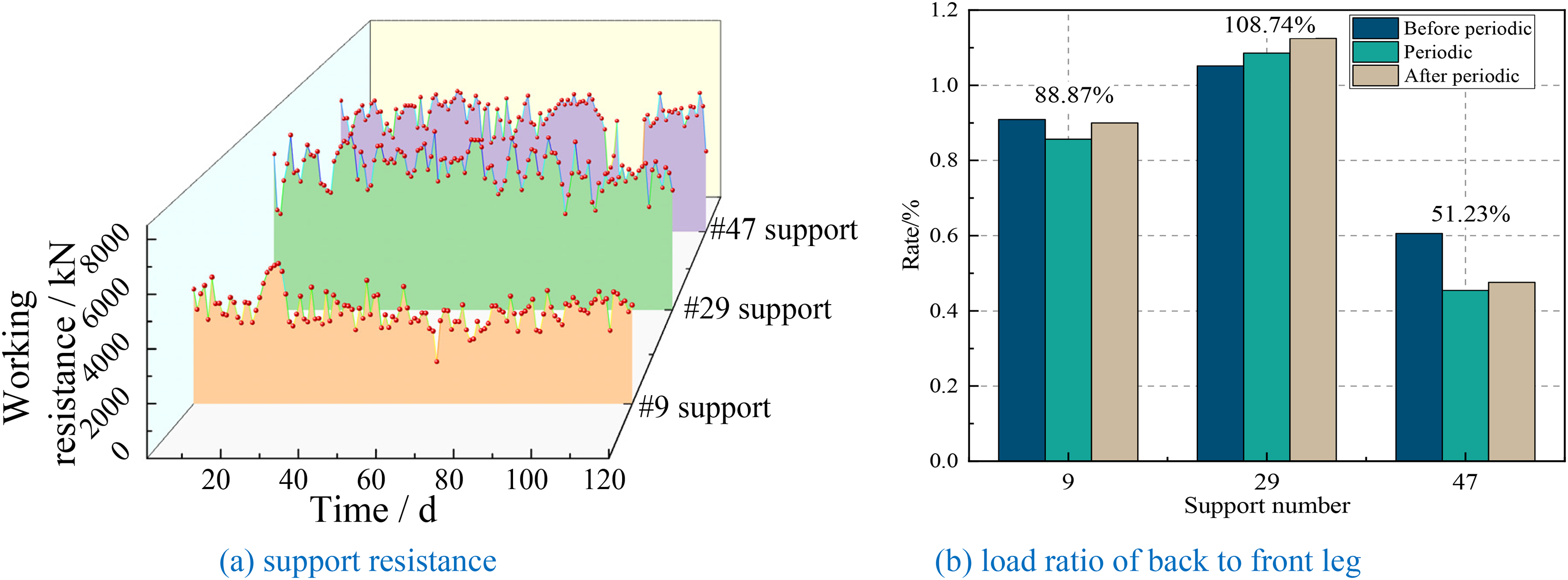
Support resistance and load ratio of back to front legs in different areas. (a) support resistance (b) load ratio of back to front leg.
Discussion
Characteristics of regional strata behavior
Combined with section ‘Results’ and ‘Monitoring results’, affected by the non-uniform filling effect of caving gangue, the space-time evolution characteristics of roof macroscopic structure are shown in Figure 17. In the mining of steeply dipping seam, the movement of gangue is a ‘time + space’ process. Not only the immediate roof falling with the support moving but also the main roof and overlying strata falling in the middle and upper part falling along the working face tendency-filling to the lower part. A non-uniform filled zone with full, completed and partial-filled area is formed in the deep gob where the overlying strata are fully collapsed, and an inverted triangular airspace is formed on the floor gob in upper part behind support, as shown in Figure 17(a). Compared with the deep gob, the gangue filling characteristics of the gob behind the support have more significant influence on the surrounding rock disaster and stability control of the working face.
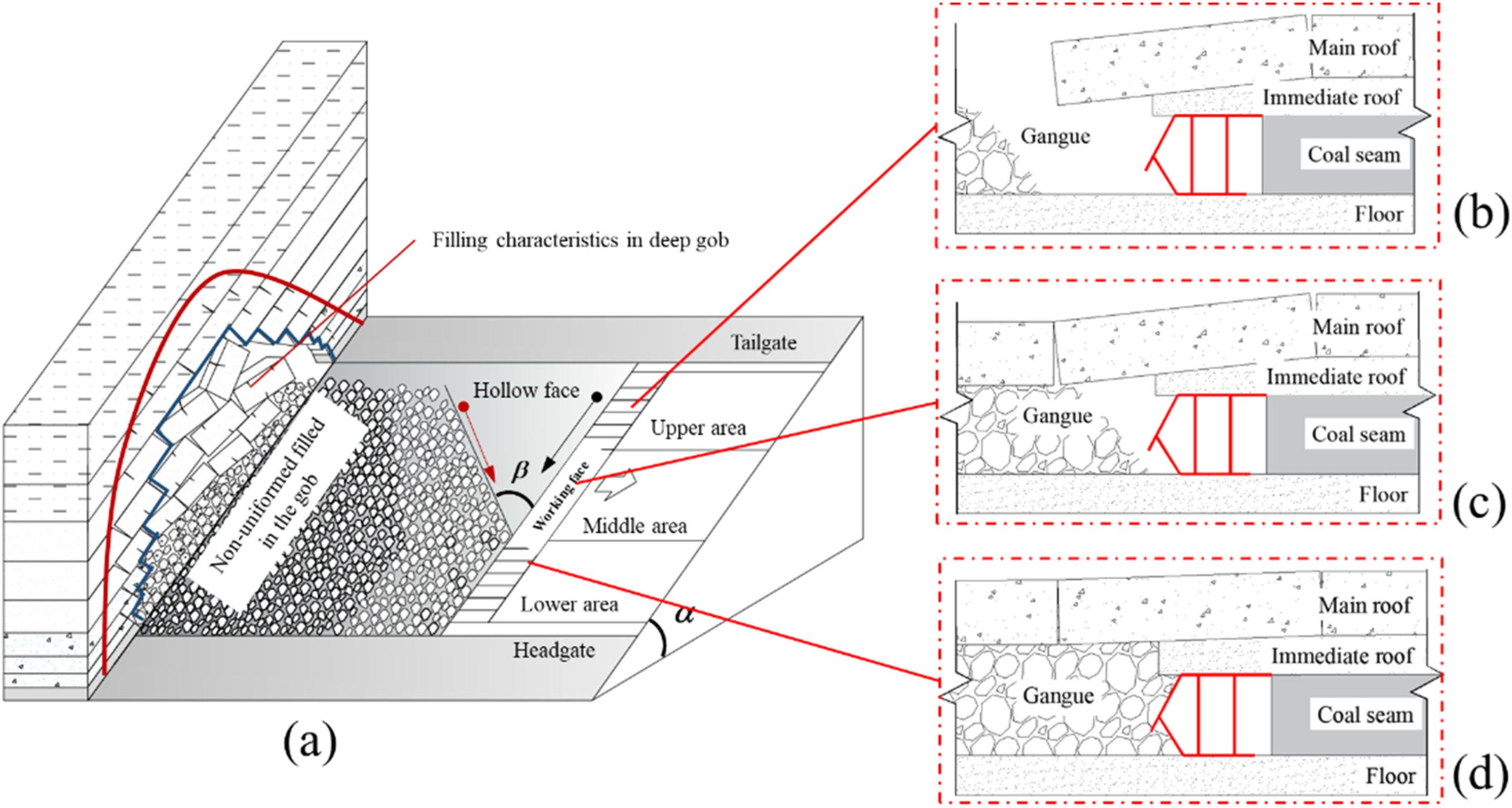
Three-dimensional asymmetric failure migration diagram of strata in longwall mining of steeply dipping seam.
Anti-rotation and anti-skid device diagram of support.
In the upper part of the working face, the filling amount of gangue in the gob behind the support is small, and the filling gangue is relatively far away from the support. There is no gangue constraint behind the main roof, and the broken and collapsed main roof rolls (slides) to the middle and lower areas of the working face, and cannot form a hinged rock beam structure along the strike. The residual immediate roof above the support canopy is short, and the loading position is at the front of the canopy, resulting in the load of the front leg greater than that of the back leg of the support. The cutting and rotary amplitude of the main roof in the strike and dip direction is much larger and in the process of working face advancing, it is easy to occur rotary instability and form empty area, as shown in Figure 17(b).
In the middle part of the working face, the gob behind the support is in a semi-filling state, and the filling density is weaker than that in the lower area. The main roof forms a hinged beam structure along the strike, but its stability is weaker than that in the lower area. The support is susceptible to impact load, and the large rotation of the main roof will make the load point of the roof on the support move backward slightly. Therefore, the load of the back leg is slightly larger than that of the front leg of the support, and the load values of the two columns are large. The ‘support-surrounding rock’ system has poor stability, as shown in Figure 17(c).
In the lower part of the working face, the gangue filling is full and the compactness of the filling body is large. The length of the main roof suspension beam is long, the subsidence and rotation are small, the strength of the mine pressure is small, and there is even no obvious periodic pressure characteristics. The roof collapse in this area is not sufficient, and there is no obvious ‘three zones’ feature, as shown in Figure 17(d).
Technical measures of support control
Scientific and reasonable support working resistance and strict support control technology is the key to ensure the stability of ‘support-surrounding rock’ system:
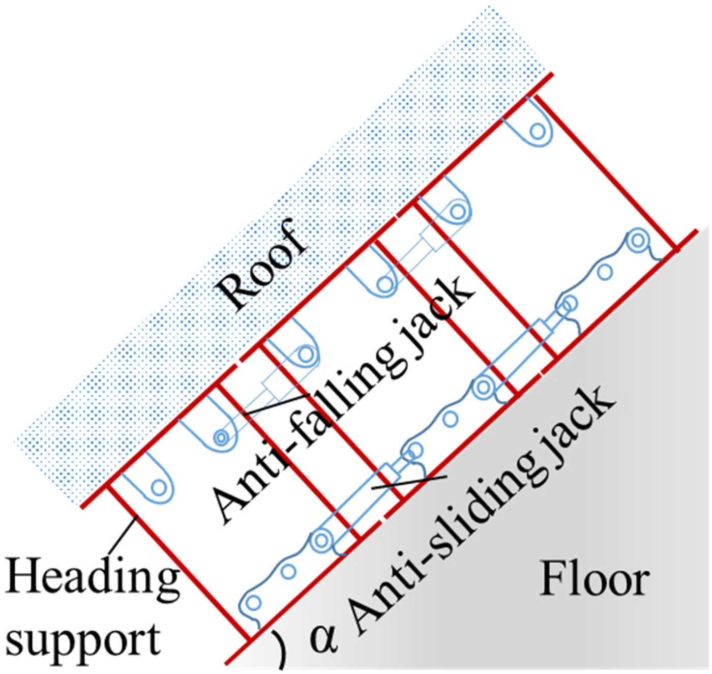
Set heading support to improve the stability of working face support system. In general, the heading support is arranged at headgate T-junction to easily control the support sliding and adjust the direction of the support. Add an anti-falling jack between the adjacent top beams and an anti-sliding jack between support bases to adjust the direction of the support and keep it consistent with the mining direction, as shown in Figure 18. Increase the initial force and working resistance of the support to maximize the liquid supply pressure of the pump station. Phenomenon of distortion, sinking and squeezing caused by support slide should be adjusted in time. Strengthen the investigation of damaged parts of the support, timely replace the damaged leg, unqualified pipeline and sealing ring, failure safety valve, etc., to ensure that the support runs under normal resistance. Under the premise of ensuring that the support has sufficient strength for the roof, a large number of high-strength plates should be used to meet the strength requirements of the support, and the weight of the support is reduced as much as possible to improve the stability of the support and reduce the difficulty of adjustment. Increase the base area as much as possible and reduce the pressure on the floor to reduce the damage of the support to the floor. The flexible canopy structure of the support is reformed, and the flexible canopy is rigidly fixed with the fixed canopy to reduce the control top distance and prevent the flexible canopy from bowing. In the mining process of steeply dipping coal seam, due to the angle of seam exceeds the natural repose angle, there are problems such as sliding (rolling) and splashing of coal gangue. In order to ensure safe production, the following protective measures are taken: a gangue net is established along the inclined direction of the working face, a gangue curtain is installed on every 10 sets of supports in the front beam of the hydraulic support, and a safety protection room is established between the front and rear columns of the support. Gangue net structure and application are shown in Figure 19. Arrangement of intelligent mining pressure monitoring instrument to carry out all-round continuous dynamic monitoring of mining pressure and forecast the roof weighting time of working face. Designate a special person on the working face periodic pressure real-time tracking observation statistics, including pressure step, pressure intensity, duration and other parameters, in order to accurately grasp the law of mining pressure behavior. Strengthen the training and management of workers on the operation of the support, strictly implement each control detail of the support, and strictly prohibit the control of the support in violation of the operation process (such as the insertion of the guard plate into the coal wall) to ensure the quality completion of each process.
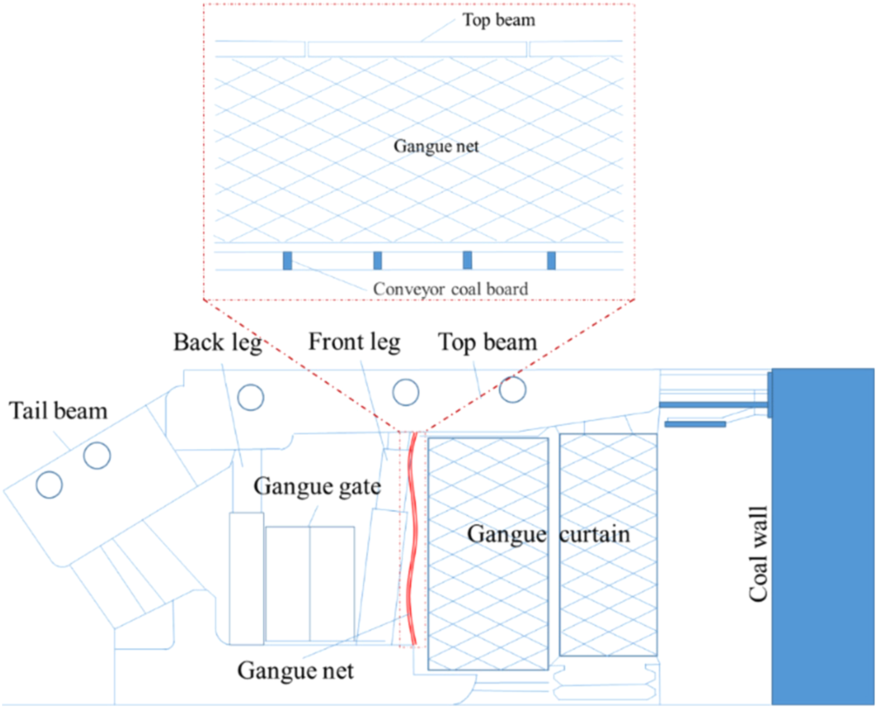
Gangue net structure and application.
Conclusions
Under the action of angle-gravity field, the immediate roof gangue slips downward and fills the lower part, and the inverted triangle hollow face begins to appear on the floor. As the working face continues to advance, the hollow face and the cavity area formed an ‘inverted triangular airspace’ in the gob behind the support. Gangue filling presents regional characteristics of ‘fully-filled, complete-filled and partial-filled’ in deep gob. The angle between the gangue pile and the horizontal plane decreases continuously from the lower part to the upper part of the working face, except for the anti-masonry structure.
When the advancing distance of the working face is small, the peak distribution of horizontal, vertical and combined displacement of the roof is in the middle and upper part. The deformation and failure of the roof in the lower part is less affected by gangue filling. With the increase of advancing distance, the breakage degree of surrounding rock increases, and the cavity area appears in the upper part. The hinged phenomenon of gangue inside the breaking envelope surface is obvious, and the horizontal, vertical and combined displacements of the roof are large. Outside the failure envelope surface, the deformation degree of the upper suspended roof as the main bearing structure is smaller than that of the hinged position.
The evolution of abutment pressure at the T-junction shows an ‘increase-stability’ trend. The peak value and concentration coefficient at headgate T-junction are greater than those at tailgate T-junction. The unbalanced load characteristics of the support are obvious. The variation range of support load in the lower part of the working face is small, and the variation range of support load in the upper part of the working face is large.
Increase the initial force and working resistance of the support to maximize the liquid supply pressure of the pump station and adjust the support position timely to improve the stability of support. Intelligent mining pressure monitor should be arranged to carry out all-round continuous dynamic monitoring of mining pressure on working face. Effective measures should be taken to accurately grasp the law of pressure during the period of pressure.
Footnotes
Acknowledgement
The authors would like to extend their sincere appreciation to the 2130 coal mine of Xinjiang Coking Coal Group Co., Ltd and Qinghai Transportation Planning and Design Institute Co., LtD for data collection.
Declaration of conflicting interests
The author(s) declared no potential conflicts of interest with respect to the research, authorship, and/or publication of this article.
Funding
The author(s) disclosed receipt of the following financial support for the research, authorship, and/or publication of this article: This work was supported by the National Natural Science Foundation of China, (grant number 51974227, 52274139, 52204151, 51974230, 52174126).