
Abstract
Roof regeneration in coal mining occurs when the remaining bottom slice of thick coal is re-mined. In view of the challenges of roof fall and instability support of a regenerative roof in the mining of steeply dipping coal seams, combined with the geological and engineering conditions of the working face in the Panbei Coal Mine, the mechanism of the instability of the regenerative roof and support is studied, and control countermeasures are proposed. Based on the comprehensive combination of the measurement of the roof structure, physical simulation, numerical simulation, and theoretical analysis, the cementation and compaction degree of the regenerated roof were described. The caving and sliding law of the regenerated roof after bottom slice mining was explored, and the model of support dumping and sliding instability under the roof fall state was established. The results obtained yielded three main findings. Firstly, the compaction degree of the regenerative roof is higher than that of the middle part of the working face, and the compaction degree of the upper part of the working face is the smallest. Secondly, the overburden structure instability of the bottom slice underwent six stages. The fracture of the cantilever beam and the slippage of gangue are the reasons for the enhancement of the acoustic signal at each stage. Finally, the upper part of the stope was identified as the crucial zone in the prevention and control of the support instability. A moving method of metal mesh with pressure and roof scraping was developed, and the support anti-overturning and anti-skid jack was set up to effectively control the stability of the support and roof fall, for safe and efficient mining of a steeply dipping coal seam under a regenerative roof.
Keywords
Introduction
In recent years, with the saturation of conventional coal mine resources, increasingly, steeply dipping coal seams (SDCS) with a dip angle of 35°–55° and complex enrichment conditions are being mined (Wu et al., 2014), particularly, in China (Tu et al., 2015; Yun et al., 2017). Many scholars have carried out systematic research on the mining technology of SDCS (Bodi, 1997; Deb et al., 2017), for example, top-coal caving mining and staggered arrangement roadway layout mining were successfully applied to SDCS (Wang et al., 2017b; Wang et al., 2017c; Zhao et al., 2017). Affected by the dip angle of the coal seam, after the coal seam is extracted, the surrounding rock of the stope forms an asymmetrical spatially stepped slump. After the rock stratum breaks down, a piled structure with inclination and anti-propensity is formed (Gao, 2004; Liu et al., 2015; Lv et al., 2019; Tu et al., 2017; Wu et al., 2010; Xie et al., 2018). The abutment pressure of the stope presents a “Spoon-like” stress arch form in the SDCS, which is affected by non-uniform filling of the meteorite and the self-weight of the overlying strata (Kulakov, 1995; Yang et al., 2015a,b; Yin et al., 2010). Moreover, the rib spalling in the SDCS has multiple localized and alternating evolutions. The middle of the working face tends to be a high-incidence area of the rib spalling, which is consistent with the asymmetric loading of the surrounding rock of the stope (Luo et al., 2018; Yao et al., 2017; Zhang and Wu, 2019). The anti-overturning and anti-skid of the support in the SDCS are its main technical challenges during ground pressure control. Through the establishment of a mechanical model of the support instability, the revelation of the mechanism of the mechanical instability, the unsymmetrical breakdown characteristics of the load, and the distribution of the abutment pressure, a series of anti-skid measures for the support were formulated (Lin et al., 2004; Wang and Jiao, 2016, 2017a; Wu and Yu, 1999; Yang et al., 2018).
The above research results provide the theoretical guidance on the characteristics of the surrounding rock of the stope and the stability of the support in the SDCS. However, the difference between the occurrence conditions and the mining method leads to significant changes in the characteristics of the roof of the SDCS. Among them, regeneration roof control is one of the technical challenges of surrounding rock control in SDCS mining. The main focus of the previous research on a regenerative roof is on the establishment of the mechanical model of the large deformation of the surrounding rock of the roadway, the influencing factors of the large deformation of the roadway, the determination of the key parts of the large deformation of the roadway, and the modification of the roadway support system (Ma and Wang, 2019; Wang et al., 2017d, 2019). However, there are few studies on the surrounding rock failure characteristics of the stope under the regenerative roof. Particularly, there are few studies on the characteristics of the falling and slipping of the surrounding rock in the SDCS stope.
As mentioned above, this paper focuses on the surrounding rock failure characteristics of the stope in the mining process of SDCS under the regenerated roof. Field measurement, physical simulation of acoustic emission monitoring, numerical simulation, and theoretical analysis were combined with borehole observation to explore the failure features of surrounding rocks in SDCS under the regenerated roof. The failure characteristics of the regenerated roof and the support instability mechanism were revealed. The stability control measures of the surrounding rock support were implemented, and good economic benefits were obtained. The findings of the present paper provide theoretical and technical guidance for safe stoping under similar engineering and geological conditions.
Project overview
Geological conditions
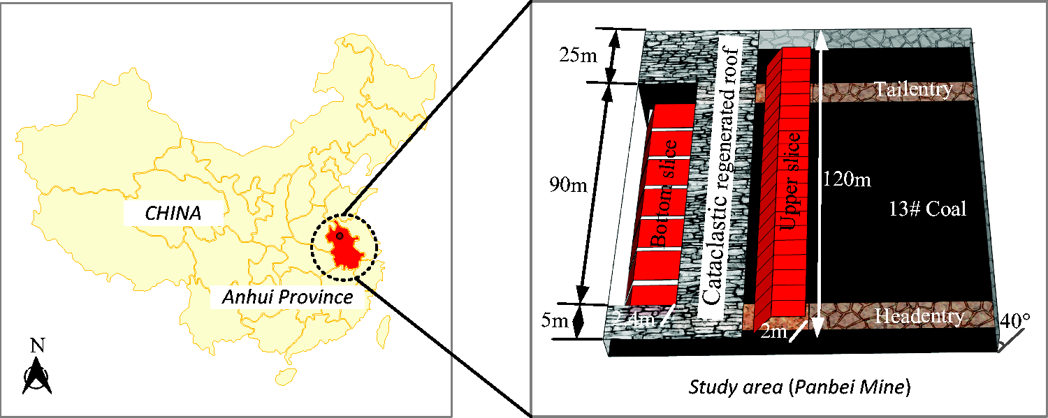
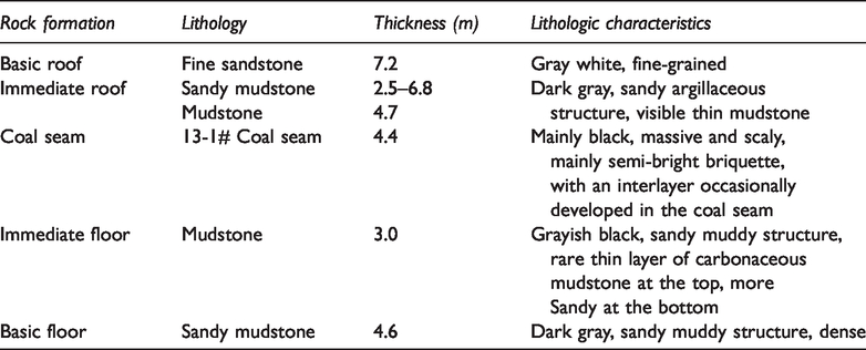
Panbei Coal Mine is located about 30 km northwest of Huainan City, Anhui Province, China. The administrative division is under the jurisdiction of Panji District of Huainan City. The mining area is 7.5 km long and 1.3–2.7 km wide, with an area of about 15.0 km2. The location map is shown in Figure 1. The elevation of the Coal seam 13# is –375 to –495 m, average dip of the coal seam is 40°, and average thickness is 4.4 m. The coal seam has a stable occurrence. The immediate roof is mostly mudstone and sandy mudstone with a thickness varying between 2.5 and 6.8 m (with an average of 4.7 m); the main floor is mudstone with an average thickness of 3.0 m. The lithologic characteristics of the coal seam and roof and floor are shown in Table 1.
Working face layout.
Lithologic characteristics.
Layout of working face and roadway
The 1212(3) working face is the first mining face of the No. 13 coal seam in Panbei Coal Mine, which is divided into an upper slice and a lower slice. The upper slice was mined in 2013, with an inclined length of 120 m and a mining height of 2 m. The bottom slice working face under mining has an inclined length of 90 m and a mining height of 2.4 m. It is arranged in the inclined lower area of the goaf in the upper slice. Specifically, the bottom slice head entry is 5 m away from the upper slice head entry, and the tail entry is 25 m away from the upper slice tail entry, as shown in Figure 1. Long wall slicing mining and fully mechanized coal mining technology for stoping were adopted. During the mining period, the No. 13 coal seam was damaged at the top of the roof and the front of the frame recurrently, which led to the collapse and sliding instability of the support. The safe mining of coal resources has been seriously affected.
Field observation, physical simulation, and numerical simulation
Borehole observation
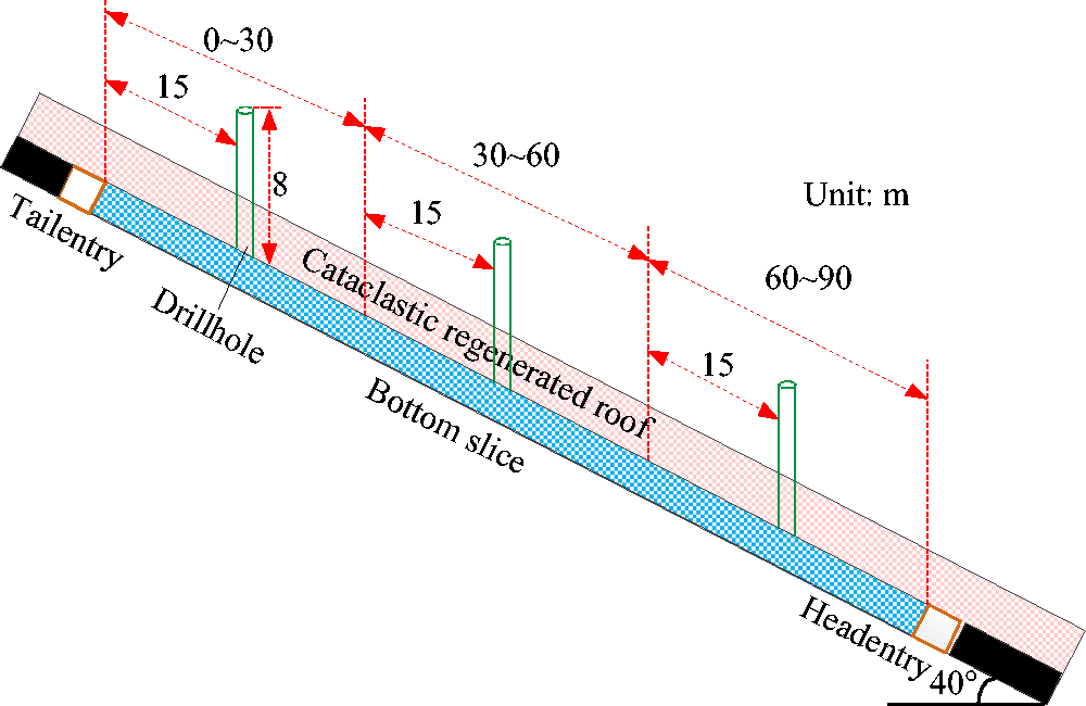
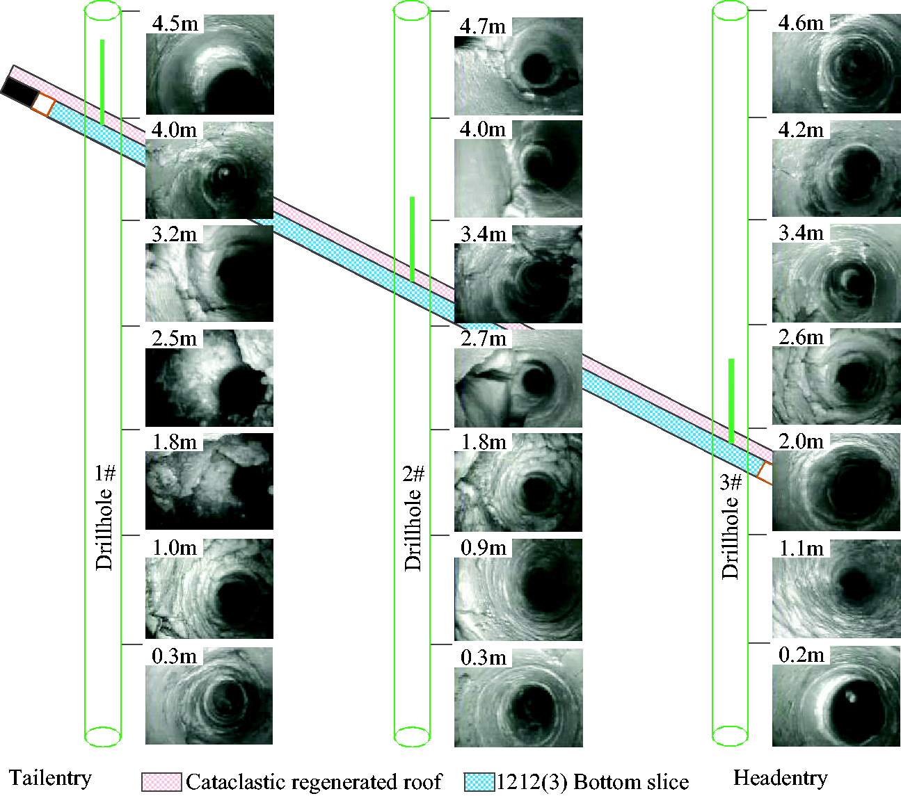
To determine the degree of cementation and compaction of the regenerated roof in the bottom slice, three boreholes were drilled in the roof of the bottom slice. These three boreholes, with a zero-inclination angle to the vertical axis, were numbered 1# to 3#, and had the same depth and diameter (8 m and 32 mm, respectively). Due to the influence of dip, roof caving after mining of the top slice exhibited asymmetrical features (the degree of caving of the upper part was larger than that of the bottom part). For this reason, the roof in the bottom slice also had zoning features. All drilled boreholes were representative of the actual enrichment status of the roof in the bottom slice: borehole 1# was 15 m from the entity coal side of the tail entry, borehole 2# was 45 m from the entity coal side of the tail entry, and borehole 3# was 75 m from the entity coal side of the tail entry. A TYGD10 stratum borehole monitor was used for the field measurement of borehole wall deformation, which made it possible to measure the surrounding rock deformation near the borehole walls, as shown in Figure 2.
Borehole layout.
Physical simulation
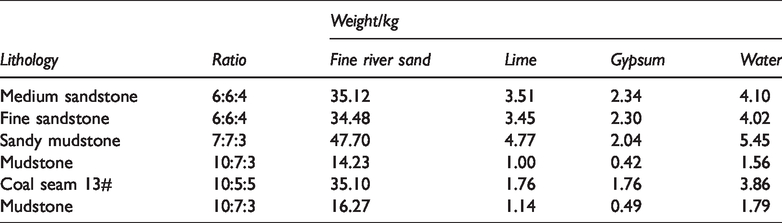
A physical simulation was performed to study the caving and slip of the regenerated roof. The dimensions of the physical simulation model were as follows: length × width × height = 2.0 m × 0.2 m × 2.0 m. Fine river sand was used as aggregate, gypsum and lime as the cementing agent, and water as the binding agent. For brevity, the details on preparation ratios and molding process are omitted and can be found elsewhere (Ghabraie et al., 2015; Zhu et al., 2011). The mechanical parameters with different lithology in the bottom slice are shown in Figure 3, and the ratios of similar materials are listed in Table 2.
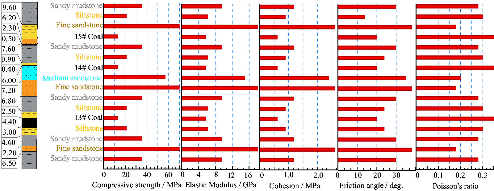
Strata histogram and physical and mechanical parameters.
Ratios of similar materials with different lithology.
The dip angle of the simulated coal seam is 40°, and the thickness is 4.4 cm. The thickness of the immediate roof (1), immediate roof (2), main roof, and immediate floor are 2.5, 6.8, 7.2, and 3.0 cm, respectively. In the simulation model, different colors are applied to distinguish the roof and floor plates of different lithology. Moreover, to monitor the elastic wave released in the process of roof fracture, an acoustic emission probe was embedded in the model. Similar conditions satisfied by the design and layout of the simulation model are shown in Figure 4, where subscript p and m in formulas indicate the prototype and model, respectively.
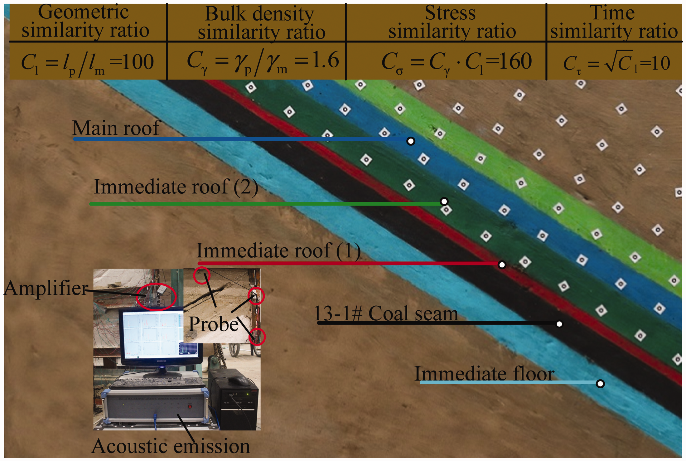
Physical model.
In the SDCS working face, the sequence of coal mining is from top to bottom, and the order of the hydraulic support motion is from bottom to top. The collapse and sliding of the overlying roof occur in the stage of moving support. To truly reproduce the roof collapse characteristics of the SDCS working face, the coal mining sequence of physical simulation test is from bottom to top. In the physical simulation, the excavation step is 10 cm, and totally nine excavations are carried out, with each excavation time being about 1 min. The acoustic emission monitoring time is from the bottom slice excavation and ends when the overlying rock reaches a stable state.
Numerical simulation
The commercial FLAC3D software package was used for simulation analysis of coal seam mining. The constitutive Mohr–Coulomb model with dimensions X × Y × Z = 200 m × 10 m × 170 m was constructed. The model has totally 10 layers of lithology, which can meet the requirements of numerical simulation. A vertical displacement constraint was imposed at the bottom of the model, and horizontal displacement constraints were applied to the four sides of the model, and a stress boundary at the top of the model. The burial depth of the coal seam was taken as 440 m, and the stress of the overlying strata in the upper part of the model was 8.75 MPa. The model scheme is shown in Figure 5.
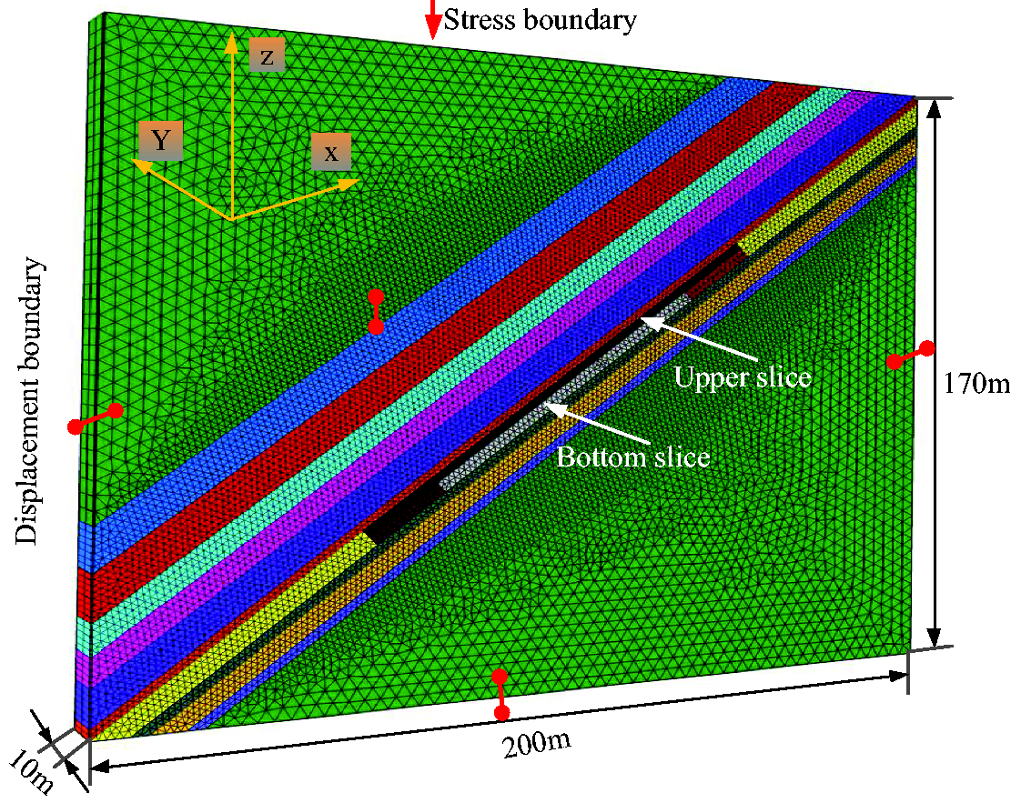
Numerical simulation model.
Analysis of observation and simulation results
Description of the borehole wall
Because of the effects of slicing mining and coal seam dip, the walls of the three boreholes under study fractured to various degrees, as shown in Figure 6. Nine grades of borehole wall integrity were defined, based on the borehole wall imaging at different heights. Grade 1 indicated the highest integrity, and grade 9 exhibited the highest fracturing degree of the surrounding rocks of the borehole wall. The integrity of the surrounding rocks of the three boreholes of the bottom slice at different heights is shown in Figure 7. Analysis of Figures 6 and 7 shows that
Morphology of borehole walls at different heights.
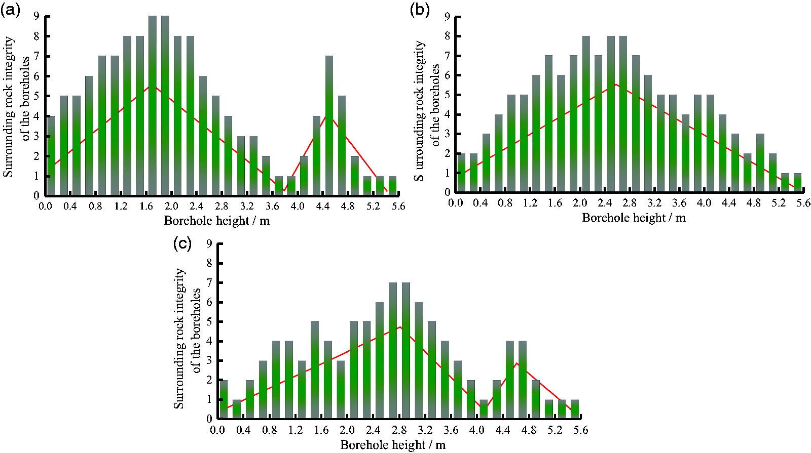
Statistics of the borehole wall integrity: (a) Surrounding rock integrity of the borehole1#; (b) Surrounding rock integrity of the borehole2#; (c) Surrounding rock integrity of the borehole3#.
The fracturing degree of the surrounding rocks at borehole 1# at 0.1–2.0 m increased with height and decreased at 2.5–4.5 m with a lower integrity degree. Below and above the height of 4.5 m, the fracturing degree of surrounding rocks differed considerably. The surrounding rocks fractured to greater extent below this height, while those above it were intact.
The surrounding rocks at borehole 2# were more compact than those at borehole 1#. The fracturing degree of the surrounding rocks at 0.9–2.1 m increased with height, and the integrity degree was lower at 2.7–4.7 m. The surrounding rocks fractured to a higher degree, when compared to borehole 1# at this height.
The compaction degree of surrounding rocks at borehole 3# at 0.1–2.0 m was higher than that at boreholes 1# and 2#. The integrity grade of the surrounding rocks at 2.0–2.6 m was higher, and the surrounding rocks were more fractured. However, beyond 2.6 m, the integrity grade exhibited a drop.
Results of physical simulation
As can be seen from Figure 8, after the top part was excavated, the fallen bodies located within 2.5 m of the working surface portion were relatively broken. At 2.5 m, a large separation layer appeared. The surrounding rock was relatively complete from 2.5 to 4.7 m. At 4.7 m, a smaller separation layer appeared, and cracks occurred at individual locations. The slump of the bottom part was small, and at 3.0 m, the fragments increased. The surrounding rock was relatively complete from 3 to 4.5 m.
Fracture characteristics of surrounding rock in stope.
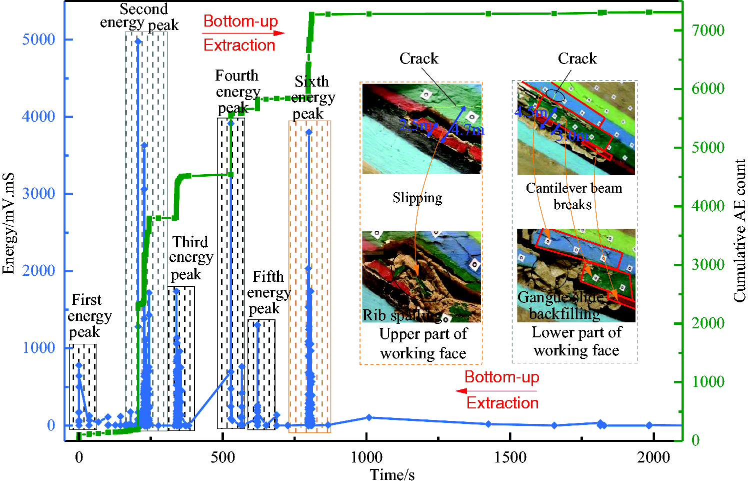
According to the time similarity ratio, the extraction of the bottom slice began when the overlying strata stabilized. Combined with the regular pattern of Acoustic Emission (AE) energy and cumulative AE ring-down count, the failure of the regeneration roof experienced six stages in the process of coal seam excavation from bottom to top.
At the first stage, after the top slice stoping, the cantilever beam (red part) of the cemented regenerated belt in the bottom part of the bottom slice was fractured. Upon the AE signal detection, this fracture manifested itself as the first energy release peak with a small intensity. With the upward excavation, the gangue slipped and filled the goaf. After the upper slice excavation, the high-level cantilever beam (green part) formed after the high-level direct top fracture broke, forming a second energy peak with the highest signal intensity. The fractured rock in the second stage slid downward to the goaf, forming a third acoustic energy peak. In this stage, the free space above the stope for rock movement increased. As a result, after the excavation of the top slice, the main roof of the crack that developed along the larger crack broke down, and the fourth energy peak was detected by acoustic emission. The signal strength was weaker than that of the second-stage fault energy peak, and a new cantilever beam (blue part) structure was formed in the overlying strata. The falling gangue continued to slide. The filling of the lower part of the working face was relatively dense, and the filling height was close to the middle and lower parts along with the coal seam dip. Therefore, the fifth energy peak was weaker than the third one. When the upward excavation reached the upper part of the stope, under the action of mining-induced stress and overburden stress, the regenerative roof above the coal pillar continued to slide without any support, and an acoustic emission appeared at the sixth energy peak, whose strength was next to that of the second energy peak.
Results of the numerical simulation
In the numerical simulation, after excavating the upper and lower layers successively, the change characteristics of the roof stress are shown in Figure 9, which is shown as follows:
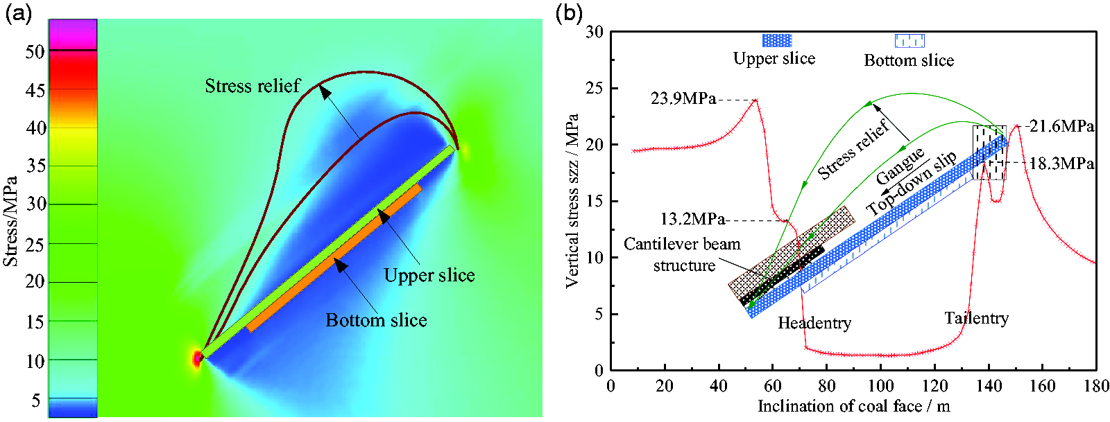
Support pressure along the dip direction: (a) the numerical simulation nephogram and (b) results of numerical simulation.
Because of a 2-m mining height in the top slice, this arch was formed at a lower horizon, in the immediate roof (2).
After the bottom slice stoping, the height of the arch in the upper part of the working face increased. In contrast, the arch in the lower part of the working face remained unchanged due to a continuous gangue filling.
With the bottom slice mining, the stress of the upper coal rock mass in the stope was “double peak,” and the stress value increased from 18.3 to 21.6 MPa. The stress release of the coal and rock mass in the lower part of the stope was relatively gentle, and the stress value increased from 13.2 to 23.9 MPa.
Comparison of the engineering site and simulation results
According to the shape of the surrounding rock in the field, the structural characteristics of the regenerated roof were consistent with the structural features of the regenerated roof reproduced by physical simulation. The numerical simulation results showed that the upper part of the bottom slice mining stope was susceptible to slip under high-stress conditions, which was consistent with the physical simulation of the excavation at the upper part of the stope midsole layer. The physical simulation results reproduce the structural characteristics of the regenerated roof better, as follows:
In the upper 0–0.5 m and lower 0–2.0 m ranges of the bottom slice, the degree of compaction and cementation were better. Within a range of 1.8–2.5 m in the upper part and 2.2–3.0 m in the lower part of the bottom slice, the rock mass sizes were larger, the degree of compaction and cementation were less appropriate, and the separation layer appeared at 2.5 m in the upper part of the regenerative roof. Within the range of 3.0–4.7 m and lower 3.0–4.5 m of the bottom slice, the surrounding rocks in the upper part were more intact.
According to the above analysis, the degree of compaction of the regenerated roof was in the order of the lower, middle, and upper parts of the working face, exhibiting the characteristics of asymmetric compaction. After the upper slice was extracted, the cantilever structure was formed in the lower rock strata of the working face. During the extraction of the bottom slice, the cantilever beam of the surrounding rock was broken, and the gangue slid downward. Acoustic emission revealed energy peaks, and the cumulative ringing showed a gradual increase. Furthermore, the degree of damage to the rock mass increased, causing the damage of the compacted layer in the lower area of the bottom slice to intensify, and the rock fragmented into smaller blocks, which easily fell between the frames. The caving of the compacted layer in the lower zone provided a free space for the upper rock strata with better integrity. When these rock masses were broken into irregular vermiculite and slid along the top beam of the supports to the lower part of the working face, the support was unstable after being pushed by the large gangue.
Support mechanical model and its verification
Stress of the support in the roof fall state
Under the condition of roof leakage at the working face, the damaged and regenerated roof falls from the support. It provides a free space for the upper large block gangue to slide. Under the action of gangue pushing, the support easily falls. At this instance, the support is subject to the lateral compression of the gangue, and the calculation formula of the lateral thrust Fc of the support is

During stoping, when the counterforce of the working resistance W moved within the rectangular area of the support base, the stability of the support changed. When the counterforce moved to a critical position, the support was in the stress equilibrium under the joint action of working resistance P, lateral force Fc, gravity G, and the floor counterforce W. On this basis, the critical mechanical model for support toppling was built, as shown in Figure 10.
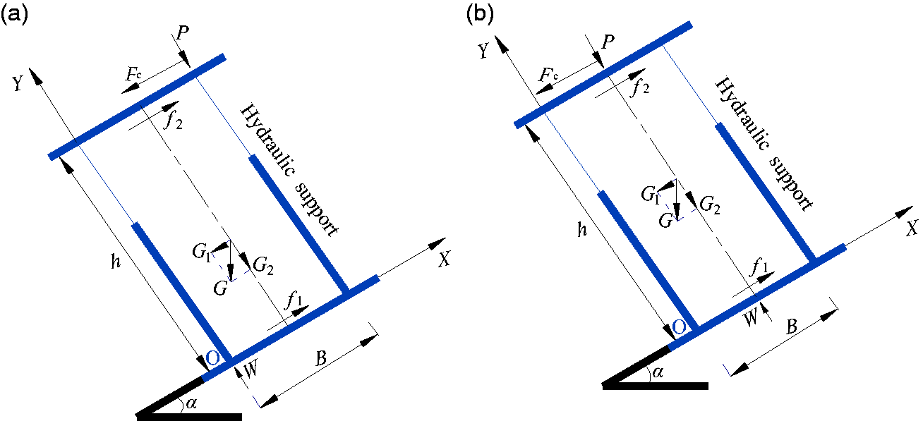
Stress of support in roof fall state: (a) support toppling mode and (b) support sliding mode.
According to the moment balance conditions, the floor counterforce W acted at point O, and the support was in a critical state of toppling (see Figure 10(a)). At this instance, the following relation is valid

The support showed a trend of sliding along the dip direction of the working face under the joint action of lateral stress Fc and gravity G. The support was in a critical state of sliding, as shown in Figure 10(b).
Then

Verification of the support mechanical model
Combined with the geological conditions of the Panbei mine, the support type, and parameters, take α = 40°, γ = 25 kN/m3, H = 4 m, Lz=5 m, B = 1.5 m, h = 2.4 m, μ = 0.37, g = 240 kN. Taking the above specific values into equations (1)–(3), it is found that the lateral thrust Fc of the support is 482 kN, and the minimum working resistance required for the support not to topple or slide is 504 kN and 768 kN, respectively.
In order to analyze the stability of the bottom layer support, before taking the stability control measures, the working resistance of 15# supports in the lower part of the stope, 34# supports in the middle of the stope, and 51# supports in the upper part of the stope were measured, as shown in Figure 11. Based on the working resistance of the support on-site, we can observe the following from the stress analysis of the support:
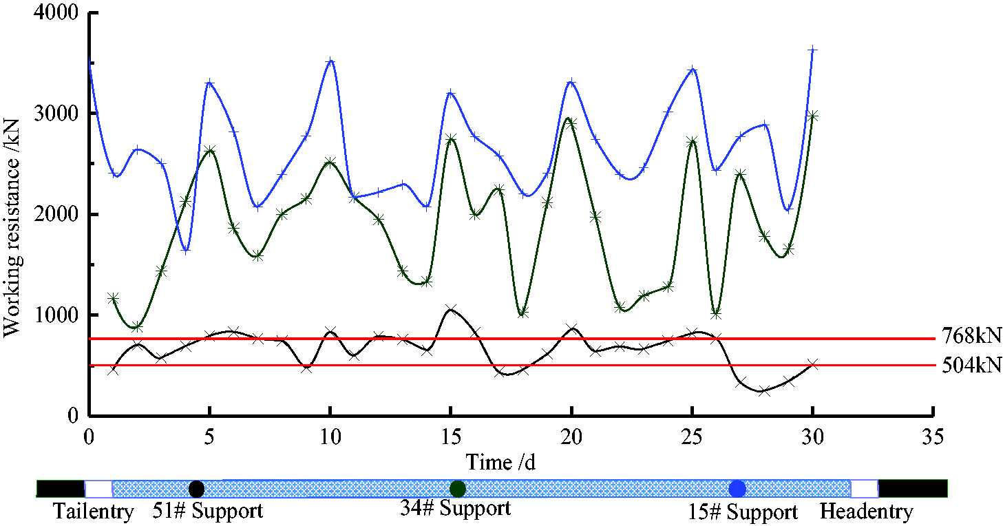
Working resistances of supports installed at different positions in the bottom slice.
The working resistances of the supports in the middle and bottom parts of the working face were higher than those in the upper part, and the largest one was observed in the bottom part. The support load along the dip direction showed an asymmetrical distribution, and the working resistance of support in the upper part was generally lower than the minimum working resistance (787 kN) needed to prevent the support instability. Therefore, the upper part of the working face was the critical region for stability control of the support system.
To prevent caving of the fractured roof in the bottom slice, advancing support with pressure technology was used. During this process, the friction factors (f1, f2) between the support, roof, and floor, respectively, should be alleviated. The respective values were introduced, and the critical value needed for advancing the support with pressure technology was calculated as μ(P+G2)+μP=0.37×(787 + 158) +0.37 × 787=640.8 kN.
For the bottom slice, ZZ6400/18/38 shield supports were used, and the maximum support force was 395.8 kN, which failed to satisfy the requirements for advancing support with the pressure technology. As the supports retreated in this process, the caving of the fractured roof seemed inevitable. Therefore, control measures for the fractured roof should be developed for the stoping.
Field application
Support-surrounding rock stability control
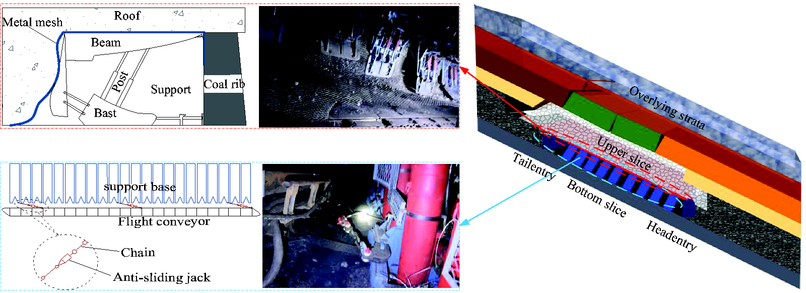
In the extraction of the bottom slice, a metal mesh was integrally laid between the support top beam and the regenerated roof. A double metal mesh was placed on the upper surface of the working face to control the broken roof. A 5.0 m×1.0 m metal mesh made of 10# iron wires with diamond-shaped holes (0.04 m×0.04 m) was laid on the working face along the dip direction. The lap of the metal mesh, along with the strike and dip directions, should be larger than 0.2 m. For the connecting metal mesh, 16# iron wires were used. The metal mesh with diamond-shaped holes, which was used to prevent caving of the fractured roof, was laid on the roof beam and perpendicular to the coal wall. The supports were advanced with pressure and roof scraping from bottom to top. During the advancing process, the “lower drop and pull faster” was achieved, and the exposed regenerative roof was supported in time to reduce the broken roof and prevent the supports from slipping and protect them from the impact of the falling rock. The bottom slice support was provided with an anti-rolling jack for every 10 sets. The stability control countermeasures of support-surrounding rock are shown in Figure 12.
Stability control of support-surrounding rock.
Effect of field application
After adopting the abovementioned countermeasures for the stability control of the regenerative roof and the support, the working resistance of the support was measured when the working surface advanced from 469 to 515 m, as shown in Figure 13. It can be seen from the analysis that the working resistance of the support presents the following characteristics: the largest in the lower part of the working face, the second in the middle part, and the smallest in the upper part. The working resistance of the supports in each area changed synchronously with a small change range, which is stable between 2000 and 4000 kN. The on-site support pressure data indicate that the implementation of the above methods and techniques has achieved good results, effectively controlling the stability of surrounding rock and supports, and improving the safe mining conditions.
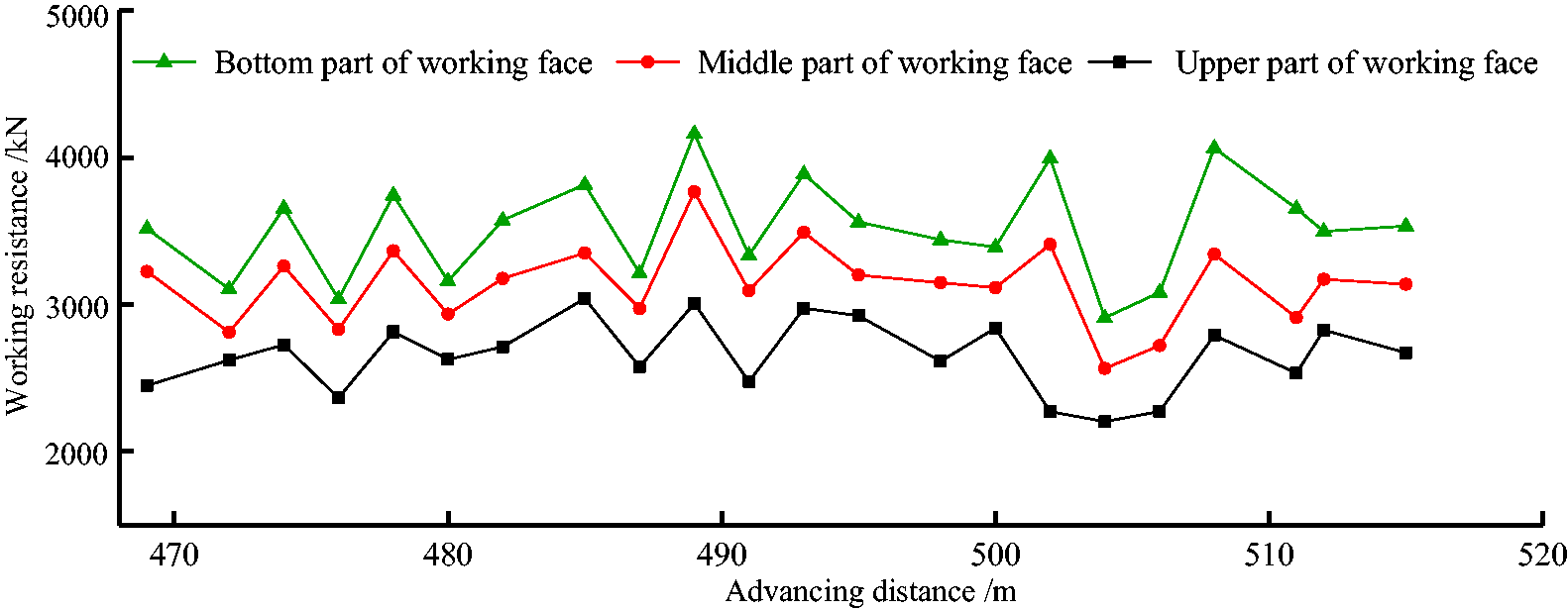
Working resistance of the support.
Conclusions
According to the borehole observations and physical simulation results, after the extraction of the top slice, the degree of compaction of the roof was in the lower, middle, and upper parts of the working face sequentially. The shape of the roof after excavation exhibits an asymmetrical feature, consistent with the SDCS. Moreover, after the top slice is extracted, the rock mass below the working face forms a cantilever beam structure. In the process of bottom slice mining, the regenerative roof experienced six stages of breaking and instability evolution. The fracture of the cantilever beam and the slip of the vermiculite are the causes of the enhancement of the acoustic emission signals at various stages. Among them, the acoustic emission signal of the cantilever beam fracture has the highest concentration. The degree of damage to the rock mass increased, causing the regenerated roof to break, forming a small block of vermiculite, which falls easily between the supports. At the SDCS working face, the mechanical model of the support is established under a state of roof fall, and the nature of support instability is shown. In addition, a formula for calculating the minimum working resistance required to maintain the stability of the support is derived. According to field measurements of ground pressure, the support in the upper part of the working face is crucial to damage prevention and control. Laying a metal mesh and a method of moving supports with pressure were used to prevent the regenerative roof from falling. Moreover, the method of setting the anti-falling and anti-skid jacks on the supports was adopted, and the supports realized combined anti-slip prevention at the SDCS working face.
Footnotes
Authors’ Contribution
All authors contributed to this paper. Xiaolou Chi prepared and edited the manuscript, and provided technical guidance for the field. Qiang Fu revised and reviewed the manuscript and processed the results of numerical simulation during the research process.
Data availability
The data used for conducting classifications are available from the corresponding author upon request.
Declaration of conflicting interests
The author(s) declared no potential conflicts of interest with respect to the research, authorship, and/or publication of this article.
Funding
The author(s) disclosed receipt of the following financial support for the research, authorship and/or publication of this article: Ke Yang supports the funds needed for the publication of the article. We acknowledge the financial support for this work, provided by the National Natural Science Foundation of China (Grant No. 51634007) and the graduate innovation fund project of Anhui University of Science and Technology (2019CX1003).