
Abstract
Directional rupture is one of the most important and most common problems related to rock breaking. The goal of directional rock breaking can be effectively achieved via multi-hole linear co-directional hydraulic fracturing. In this paper, the XSite software was utilized to verify the experimental results of multi-hole linear co-directional hydraulic fracturing., and its basic law is studied. The results indicate that the process of multi-hole linear co-directional hydraulic fracturing can be divided into four stages: water injection boost, hydraulic fracture initiation, and the unstable and stable propagation of hydraulic fracture. The stable expansion stage lasts longer and produces more microcracks than the unstable expansion stage. Due to the existence of the borehole-sealing device, the three-dimensional hydraulic fracture first initiates and expands along the axial direction in the bare borehole section, then extends along the axial direction in the non-bare hole section and finally expands along the axial direction in the rock mass without the borehole. The network formed by hydraulic fracture in rock is not a pure plane, but rather a curved spatial surface. The curved spatial surface passes through both the centre of the borehole and the axial direction relative to the borehole. Due to the boundary effect, the curved spatial surface goes toward the plane in which the maximum principal stress occurs. The local ground stress field is changed due to the initiation and propagation of hydraulic fractures. The propagation direction of the fractures between the fracturing boreholes will be deflected. A fracture propagation pressure that is greater than the minimum principle stress and a tension field that is induced in the leading edge of the fracture end, will aid to fracture intersection; as a result, the possibility of connecting the boreholes will increase.
Keywords
Introduction
Fossil fuel, such as coal, oil and natural gas, plays an important role in the existing energy system. Hydraulic fracturing is a common technology to explore and exploit these fossil fuels (Guo et al., 2020; Hou et al., 2014; Liu et al., 2018, 2019a, 2019b; Zheng et al., 2015). When the actual propagation direction of hydraulic fracture cannot meet engineering requirements, it is necessary to control the propagation direction. When the hydraulic fracture propagates along a specific direction, the process is called directional hydraulic fracturing. At present, directional hydraulic fracturing is necessary during the directional pre-cracking of the hard roof of a coal seam (Huang et al., 2017; Huang et al., 2018a; Lin et al., 2016; Wang et al., 2019; Yu et al., 2019), the weakening and caving of hard roof coal (Huang et al., 2015, 2018b), the prevention and control of rock bursts (Dou et al., 2009; He et al., 2012; You et al., 2017), roadway retention along the void, roadway formation using the top-cutting method, permeability improvement of methane-bearing coal seams and shale oil and gas reservoirs (Huang and Lu, 2018; Li et al., 2019; Lu et al., 2019).
There are still many unviewable or invisible regions in the underground environment, and the realization of a high connection rate and the precise control of the propagation direction of hydraulic fractures in coal and rock masses have become the key goals of conventional hydraulic fracturing. As we know, the in-situ stress is complex and it has an important influence on the hydraulic fracture geometrie. This influence can also effectively result in transverse and longitudinal hydraulic fractures and reorientation of hydraulic fractures (Guo et al., 2018a; Guo et al., 2019; Hou et al., 2016; Xu et al., 2005). However, scholars have always been studying methods for guiding and controlling the propagation direction of hydraulic fractures. These methods include (1) directional hydraulic fracturing technology guided by guide grooves (Deng et al., 2016, 2018; He et al., 2018; Zhang et al., 2018), wedge-shaped grooves are cut along the axial or radial direction of the borehole, and due to the stress concentration, the hydraulic fracture propagates along the wedge-shaped grooves. Due to the limitation of the stress concentration around the fracture tip of the groove depth, the initiation and propagation of directional fractures are strongly affected. Furthermore, (2) for directional hydraulic fracturing by water jet pre-slotting (Huang et al., 2018a, 2018b; Lin and Shen, 2015; Lin et al., 2015; Liu et al., 2015; Zou and Lin, 2018), a pre-slot is cut via water jet slotting along the desired direction around the borehole, and then hydraulic fracturing is performed. As a result, the hydraulic fracture first propagates along the pre-slot. However, after the formation of hydraulic fractures, the fractures will turn due to the comprehensive influence of in situ stress, mining and other factors, and the range of directional fracturing is very limited. For (3) directional hydraulic fracturing guided by control holes (Cheng et al., 2018; Zhai et al., 2012; Zhao et al., 2018), which act as auxiliary free surfaces, are placed to create a weak surface in the coal body. This method can effectively avoid stress concentration and reduce local stress to promote orientation and accelerate expansion of hydraulic fractures. As a result, the hydraulic fracture expands in the desired direction. For (4) directional hydraulic fracturing guided by a non-uniform pore pressure, the pore water pressure gradient guides the propagation of the tip of hydraulic fracture. When the pore water pressure of the control borehole is determined, the direction of hydraulic fracture propagation will shift to the control borehole in which the water is injected. The higher the pore pressure of the control borehole, the higher the stress intensity factor at the tip of the hydraulic fracture and the higher its deflection angle. Additionally (5) directional hydraulic fracturing controlled by combined boreholes (Cheng et al., 2018) was proposed based on the guidance of the control borehole and non-uniform pore pressure. Fracturing boreholes are arranged along the desired direction, resulting in the directional propagation of hydraulic fracturing. Multi-hole collaborative hydraulic fracturing can achieve the directional propagation of hydraulic fractures and improve the range of directional fracturing. At present, the fracture propagation laws of the first four types of directional hydraulic fracturing have been studied to some extent. However, the fracture initiation and propagation laws of multi-hole directional hydraulic fracturing are still being explored and perfected; thus, further in-depth study is necessary.
At present, multi-hole linear cooperative hydraulic fracturing is used to arrange multiple fracturing boreholes in the desired direction. These fracturing boreholes play a guiding role in pressure relief and the directional propagation of hydraulic fracture. Then water is simultaneously injected into all the fracturing boreholes with equal or unequal displacement, which can achieve the directional propagation of hydraulic fracturing in a short time. The more the fracturing boreholes, the better the effect of directional propagation, and the larger the range of directional propagation (Cheng et al., 2018; Guo et al., 2018b; Liu et al., 2019a; Liu et al., 2019b; Zhai et al., 2012). The effect of multi-hole co-directional hydraulic fracturing was investigated via laboratory experiment by Xinglong Zhao et al. However, the initiation and dynamic propagation processes, the spatial morphology and the propagation mechanism of multi-hole linear co-directional hydraulic fracturing remain to be studied (Zhao et al., 2018).
In this article, XSite software with water flooding displacement as boundary conditions is utilized to study the initiation and dynamic propagation processes and the spatial morphology of multi-hole linear co-directional hydraulic fracturing to determine if the change of the ground stress field is induced by the propagation of the hydraulic fracture. The mechanism of fracture reorientation, which is induced by change of the ground stress field, is analysed. Additionally, several indices, such as water pressure change, number of micro fractures and initiation pressure of hydraulic fracturing, are analysed. The results provide theoretical support for guiding engineering practice.
Principle of numerical simulation with XSite software
XSite is a powerful three-dimensional hydraulic fracturing numerical simulation program based on the Synthetic Rock Mass (SRM) and lattice methods. It currently has a functionality that allows simulation of fluid injection into one or multiple boreholes each with one or multiple clusters. The injected fluid can be Newtonian or power-law, and can contain proppant. Hydraulic fracturing in a homogeneous, non-homogeneous or jointed medium can be simulated. Arbitrary and, if desired, non-uniform stress field (i.e. varying from one layer to another), defined by magnitudes and orientations of the principal stresses, can be initialized in the model. It can generate data on micro seismicity associated with both formation of microcracks and slipping on the pre-existing joints. It resolves general hydraulic fracture interactions, including propagation in naturally fractured reservoirs with deterministically or stochastically generated discrete fracture networks (DFNs). The models are used to conduct fully coupled hydro-mechanical simulations.
Lattice method
Based on the Distinct Element Method (DEM), with particles and contacts replaced by nodes and springs, respectively, nodes with masses are arranged quasi-randomly and, connected by normal and shear springs that, can fail in a brittle manner (i.e. micro-cracks). Micro-cracks may coalesce to form macro fractures with a propagation criterion based on the fracture toughness. Spring elastic/strength parameters are calibrated automatically based on the fracture toughness and unconfined compressive and tensile strengths. Pre-existing joints are represented by the smooth-joint model that accurately predicts slip and the opening/closing of joints. Thousands of pre-existing joints (DFN) can be included.
The lattice used in XSite is a quasi-random assembly of nodes connected by nonlinear springs. Node locations are derived from the centroids of a packed assembly of spheres. The resulting array of centroids is provided to the user of XSite as a built-in data set. Different resolutions and material properties are derived from the original data set by scaling. XSite is well-suited for the direct simulation of highly nonlinear behaviour such as fracture, slip and the opening/closing of joints. Thus, the law of motion for translational degrees of freedom consists of the following central difference formulae for each node (Itasca, 2011)
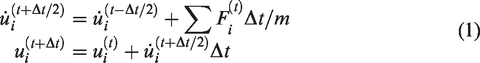
After all nodes have been visited (by applying equation (1) to each one), a scan of all springs is performed. If a spring is unbroken, then the following calculations are performed at time t (time superscript omitted for clarity)

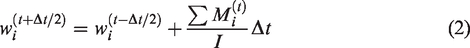
Here, the superscript “rel” denotes “relative”, and “A” and “B” denote the two nodes connected by the spring
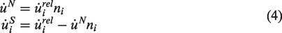
Here, “N” denotes “normal”, “S” denotes “shear”, ni is the unit normal vector, and the Einstein summation convention applies to repeated indices. The normal and shear forces are updated as
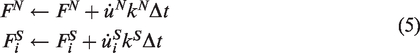
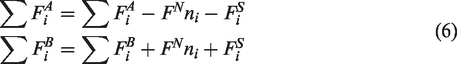
For a regular spring (part of the intact rock material), the vector ni is the unit normal from node A to node B, i.e.
As soon as the gap becomes zero, the spring calculation reverts to that of equation (5). Thereafter, the spring separates again (g > 0, FN = 0) when the normal force becomes greater than zero. For a spring that is part of a joint segment, the shear force is limited to the maximum frictional force when the normal force is compressive (FN<0)
If
Criteria for fracture propagation
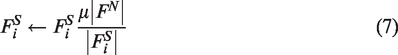
A criterion for fracture propagation based on energy principles in general, and the J-integral, was investigated and implemented in XSite. The main advantage of using a criterion based on the J-integral is that it is resolution-independent and allows systematic application.
The energy release rate can be evaluated using the J-integral (Huang, 1999). The contour integral J is defined as follows:
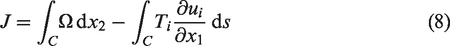
The J-integral has interesting properties (Parker, 1981). In the case of a closed contour, J = 0. Also, the J-integral taken along an unclosed contour between unloaded crack surfaces is path-independent. In General
The stress intensity factor, KI, is derived from
Flow model
The flow in the fractures, both pre-existing (specified as the model input) and newly created (by breaking the lattice springs), is solved within the network of fluid nodes connected by the pipes (one-dimensional flow elements). The fluid pressures are stored in the fluid nodes that act as penny-shaped microcracks located at the broken springs or springs intersected by the pre-existing joints. Flow rates are calculated for each flow pipe. As the microcracks are created, due to breaking of the lattice springs as dictated by the forces in the lattice, the code automatically creates new fluid nodes and connects them, using flow pipes, based on spatial relation with the existing flow network.
It is assumed that the pipe width (in the joint plane) is equal to its length. The flow rate along a pipe, from fluid node “A” to node “B”, is calculated based on the following relation


Clearly, when the pipe is saturated, s = 1, the relative permeability is 1. Dimensionless number β is a calibration parameter, a function of fluid resolution, used to match conductivity of a pipe network to the conductivity of a joint represented by parallel plates with aperture a. The calibrated relation between β and the fluid resolution is built into the code for discrete values of fluid resolution in a tabular form. The code linearly interpolates for β between the discrete table values.
The evolution of the flow model with time is solved using an explicit numerical scheme. The pressure increment, ΔP, during the flow timestep, Δtf, is calculated as
The code has the option to allow negative pressures. These are necessary to match the conditions of the exact solutions (with no lag) used for the validations.
Fluid/mechanical coupling
A new coupled fluid-mechanical scheme, Mechanical Incompressible Fluid (MIF), to model the mechanisms associated with hydraulic fracturing and/or fluid injection in pre-existing joints has been proposed by Peter Cundall. After testing, it was implemented in HF Simulator. The new scheme is applicable to situations in which the rock compressibility is much larger than that of the fluid. One of the main advantages of this scheme is the larger (both mechanical and flow), explicit timesteps required for numerical stability. In the new scheme, a stable timestep is proportional to rock compressibility multiplied by the discretization length, which is orders of magnitude greater than the stable timestep in the current schemes, proportional to fluid compressibility multiplied by fracture aperture. (The rock and fluid compressibilities are roughly of the same order of magnitude, but the fracture aperture is typically orders of magnitude smaller than the discretization length.) The scheme and its effects on timesteps are described again briefly in this section.
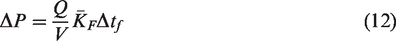
Consider an element of rock that includes a single joint. The element has the dimension of the lattice resolution, R, and the joint is represented mechanically by the SJM, in which the unit normal vector is taken as that of the through-going joint plane rather than the normal vector linking the two associated nodes. Figure 1 illustrates the mechanical arrangement in the normal direction. The stiffnesses have units of [force/displacement]. The entire discussion in this section is in terms of one-dimensional stiffnesses. Thus: kF = KFA/a, where KF is fluid bulk modulus, A is the apparent area of the joint element (in the order of R2, where R is the lattice resolution or discretization length) and a is the joint aperture; and kR = KRA/R, where KR is rock bulk modulus. Because R ≫ a, typically kF≫kR.
Schematic of lattice element with embedded fluid-filled joint, normal direction.
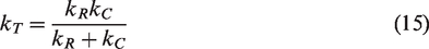
The combined joint normal stiffness, kC, is (kJ + kF) , and the total element stiffness, kT, is
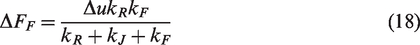
The increment in force, ΔF, for the element, due to an incremental total relative displacement, Δu, is

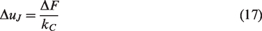
The increment in fluid force is Δ FF = ΔuJkF, which (after some substitution) becomes
If kF≫kR, then the fluid pressure increment approaches

Thus, the fluid pressure increments depend only on lattice spring stiffness. Because the stable timestep is inversely proportional to maximum stiffness in the model, this means that the stable mechanical timestep for hydro-mechanical simulation is practically the same as for uncoupled simulations. In the current schemes, the pressure increment is proportional to apparent fluid stiffness, resulting (because kF≫kR) in reduction of the mechanical timestep in the coupled calculations by orders of magnitudes compared to the timestep in uncoupled calculations.
The apparent fluid modulus (used in the flow part of the model and affecting the stable flow timestep) also is changed as a result of the new algorithm. Consider a fluid “displacement” increment, ΔuF (derived from a flow imbalance, ΣQ, in the joint), which is imagined to be injected in series with the fluid spring, kF, at each fluid timestep. The increment in fluid force is, then
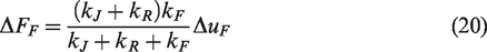
The pressure increment is ΔP = ΔFF/A, which approaches

In the limit kF≫kR

The joint spring carries the total force, which affects the force balance and the motion. However, the effective stress is considered in assessment of slip or opening of the joint. If, in the MIF scheme, the aperture is increased by 2, the timestep is divided by 8. To prevent a prohibitive decrease of fluid flow timestep, there is an upper bound to the apparent fracture aperture. Note that this limit applies to the flow resistance—not the fluid storage volume.
The stable mechanical step is typically smaller than the stable fluid step. In the MIF scheme, uniform density scaling is applied by giving the mechanical timestep a value equal to that of the fluid. (In this technique, inertial masses are multiplied by a factor such that the computed mechanical timestep is equal to the fluid timestep. Gravitational masses are unaffected.)
Solution method
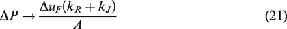
Where joint (discontinuity) planes cut springs, the angle of the plane is respected (not the spring orientation). Thus, shear and normal compliances for the joint are used. In addition, slip and the opening/closing of joint elements are modelled. Sliding on joint planes is independent of the local orientations of component springs. An explicit central difference solution scheme that is well-suited for the simulation of highly nonlinear behaviour, such as fracture slip and the opening/closing of joints, is used by XSite. The lattice method is efficient because it pre-calculates geometrical and interaction data and uses simplified equations of motion (Figure 2). It has been developed for stiff, brittle rock in which failure occurs (a) at small strain and (b) by tensile rupture (e.g. fracture of rock bridges, hydraulic fracturing, and blast damage).
Solution method.
Verification of the mathematical model
Geometric model
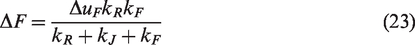
A three-dimensional homogeneous model with a size of 20 × 20 × 20 m is utilized in this numerical simulation (Figure 3). The maximum principal stress σ1 in the horizontal direction is 6 MPa, the minimum principal stress σ3 in the horizontal direction is 2 MPa, and the middle principal stress σ2 in the vertical direction is 5 MPa. Three boreholes are arranged in a linear direction. The middle borehole is in the centre of the upper surface of the model. The distance between the axes of the adjacent two boreholes is 6.92 m. The diameters of the three boreholes are 8 mm. The angle θ between the line connected by the borehole’s centre and the maximum principle stress σ1 is 15°. All three boreholes are fracturing boreholes. When hydraulic fracturing is conducted, the water is injected at a displacement of 0.5 L/s.
Geometric model.
The lattice resolution of this model processed by XSite software is 0.04 m, and the lattice grid edge is 0.2 m. The number of nodes is 2424, and the number of springs is 11,160.
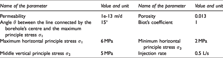
Selection of the parameters for the numerical simulation
To ensure that the numerical calculation can more closely simulate the real physical experiment, the real physical parameters of the experimental sample are adopted in the numerical simulation as much as possible. The relevant parameters used in this numerical simulation are shown in Table 1. The same value of maximum horizontal principle stress σ1 6 MPa, Middle vertical principle stress σ2 5 MPa and Middle vertical principle stress σ3 2 MPa as the value of laboratory experimentation is utilized in the numerical simulation.
Parameters selected for the numerical simulation.
Comparison of numerical simulation and experiment results
At present, the water injection pressure is defined as the boundary condition in most numerical simulation software for hydraulic fracturing, while real-world hydraulic fracturing is based on water injection displacement. However, the water injection displacement is specified as the boundary control condition by XSite software, which is closer to the actual situation field test, to realize the numerical calculation of the hydraulic fracturing process. The results of the XSite numerical simulation show that when water is injected at equal displacement into several fracturing boreholes at the same time, the hydraulic fracture (the red dotted line in Figure 4(a)) roughly extends along the line of the borehole’s centre. Due to the influence of ground stress at the boundary of the test block, fracture propagation tends to be in line with the direction of the maximum principal stress σ1 at the boundary, which is commonly referred to as the boundary effect. In addition, the red dotted line in Figure 4(a) is the projection line of the fracture surface (Figure 4(b)) generated by hydraulic fracturing on the upper surface of the test block. It is the spatial morphology of the fracture surface of hydraulic fracturing that can be intuitively seen in Figure 4(b). The results of the fracture surface of hydraulic fracturing obtained by the numerical simulation and laboratory experiment conducted by Zhao Xinglong et al. are generally consistent. It is indicated that (1) the fracture surface generated in the rock mass by multi-hole linear co-directional hydraulic fractures is not a pure plane but rather a curved spatial plane. In the homogeneous test block with different materials, the propagation of the hydraulic fracture and the spatial morphology of the fracture surface of multi-hole linear co-directional hydraulic fractures are basically the same. Furthermore, (2) it is feasible to utilize XSite software to study the fracture initiation and propagation laws of multi-hole linear co-directional hydraulic fracturing.
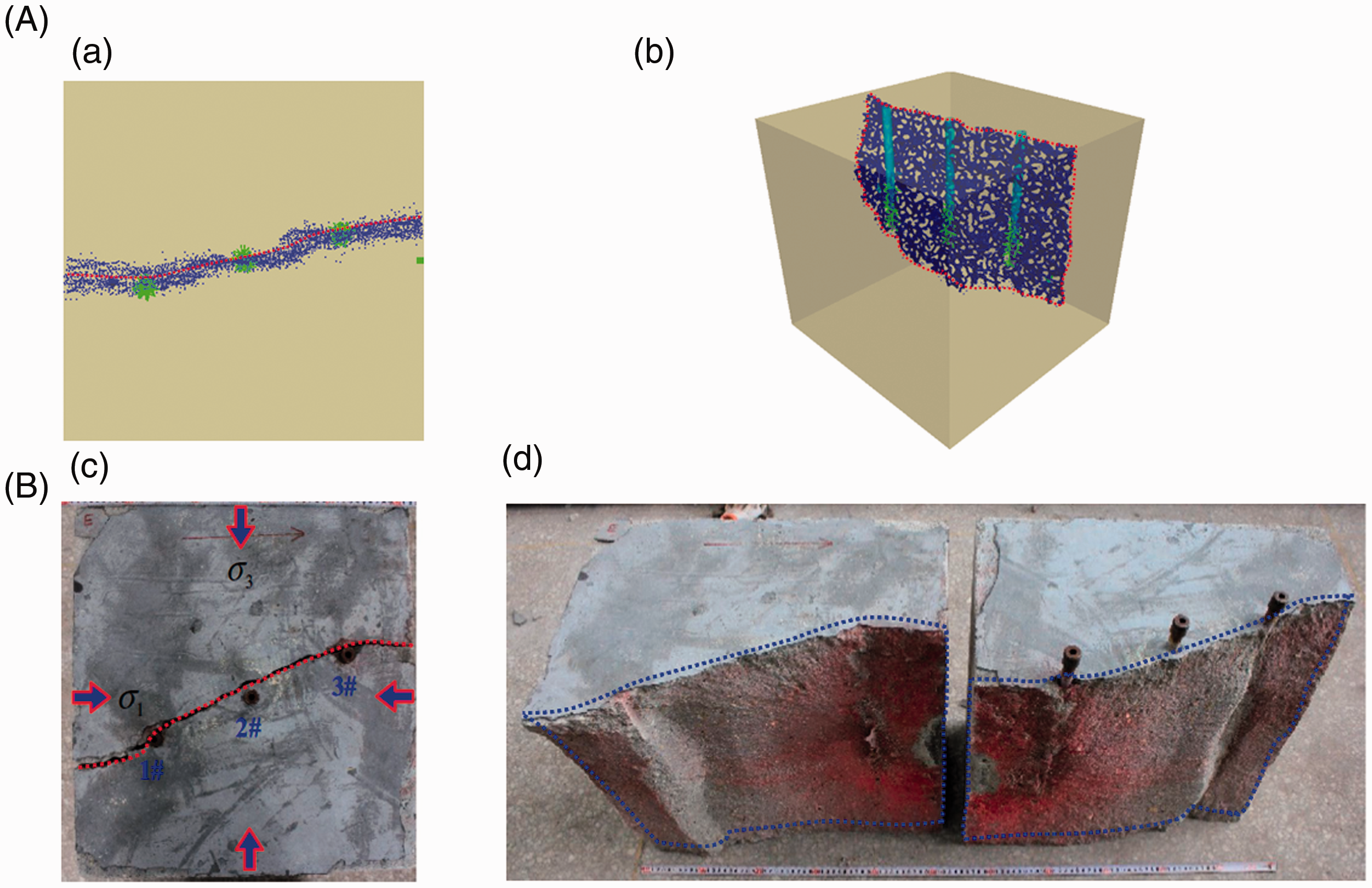
Comparison of the results of numerical simulation and laboratory experimentation. (A) Results of numerical simulation: (a) top view of the fracture surface of hydraulic fracturing and (b) side view of the fracture surface of hydraulic fracturing. (B) Results of laboratory experimentation: (c) top view of the fracture surface of hydraulic fracturing and (d) side view of the fracture surface of hydraulic fracturing.
Initiation and propagation laws of multi-hole linear co-directional hydraulic fracture
Initiation and dynamic propagation processes of hydraulic fracture
By combining the changes in the water pressure and the number of micro-cracks over time (Figure 5) with the initiation and propagation processes of hydraulic fractures (Figure 6), the process of multi-hole linear co-directional hydraulic fracturing can be divided into four stages: water injection boost, hydraulic fracture initiation, unstable propagation of hydraulic fracture and stable propagation of hydraulic fracture. For these four stages, the detailed processes are as follows. (1) In the water injection boost stage, the water pressure of each fracturing borehole increases with the increase in the amount of water injection. Due to the small size of the borehole, the whole borehole is filled with water in a very short time, and the external performance increases rapidly with water pressure (Figure 5). This stage is relatively short, and fracturing is not initiated (Figures 5 and 6(a)). (2) In general, the rock mass is strong, brittle and with low plasticity, resulting in the increase in energy accumulation with the increase in water pressure. When the water pressure at the bottom of the borehole reaches the rupture pressure (pb = 48 MPa), rupture will occur immediately, resulting in the initial fracture of the rock mass. The hydraulic fracture initiates along the axis of the borehole and is consistent with the direction of the maximum principal stress σ1 (Figures 5 and 6(b)). During the initiation of hydraulic fracture, the fracture expansion rate is very fast when the rock ruptures for the first time, and a large amount of energy is released. Additionally, some micro-cracks will be quickly generated around the borehole, and the number of micro-cracks will increase rapidly over time (Figures 5 and 6(b)). (3) After the fracture is opened, the pressure at the bottom of the hole decreases gradually. With the continuous injection of water, the accumulated energy of the rock mass cannot be released stably; thus, the unstable propagation of the hydraulic fracture occurs, and the water pressure at the bottom of the borehole drops obviously and fluctuates to some extent (Figure 5). When the stress or deformation at the fracture tip reaches the strength of the material, the fracture will expand forward from the wall of the borehole. The duration of the unstable propagation stage in this simulation was 134 s, and in this time, 1781 microcracks were generated. (4) As water is continuously injected into to borehole, the energy in the rock mass starts to undergo stable release; this stage is referred to as the stable expansion of hydraulic fracturing. In this stage, the water pressure over time curve can be approximated by a horizontal line. The stable water pressure is called the pressure at fracture extension pprog, and under this pressure, the hydraulic fracture continues to expand stably. The duration of this stage in the simulation was 356 s, and during this time, 2418 microcracks were generated. The initiation and propagation of hydraulic fractures caused by multi-hole linear co-directional hydraulic fracturing cause the local ground stress field to change. As a result, fracture propagation is deflected, resulting in the gradual connection of the micro-fractures and the breakthrough of macroscopic fractures (Figure 6(c) to (f)).
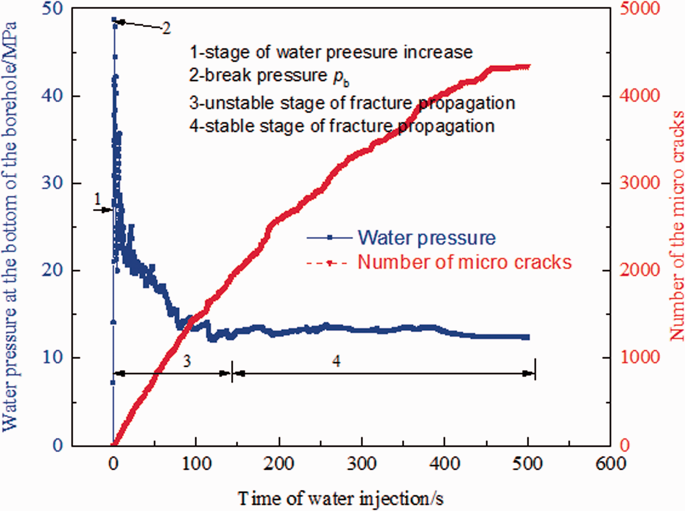
Change curve of water pressure at the bottom of the borehole and the number of hydraulic fractures over time.
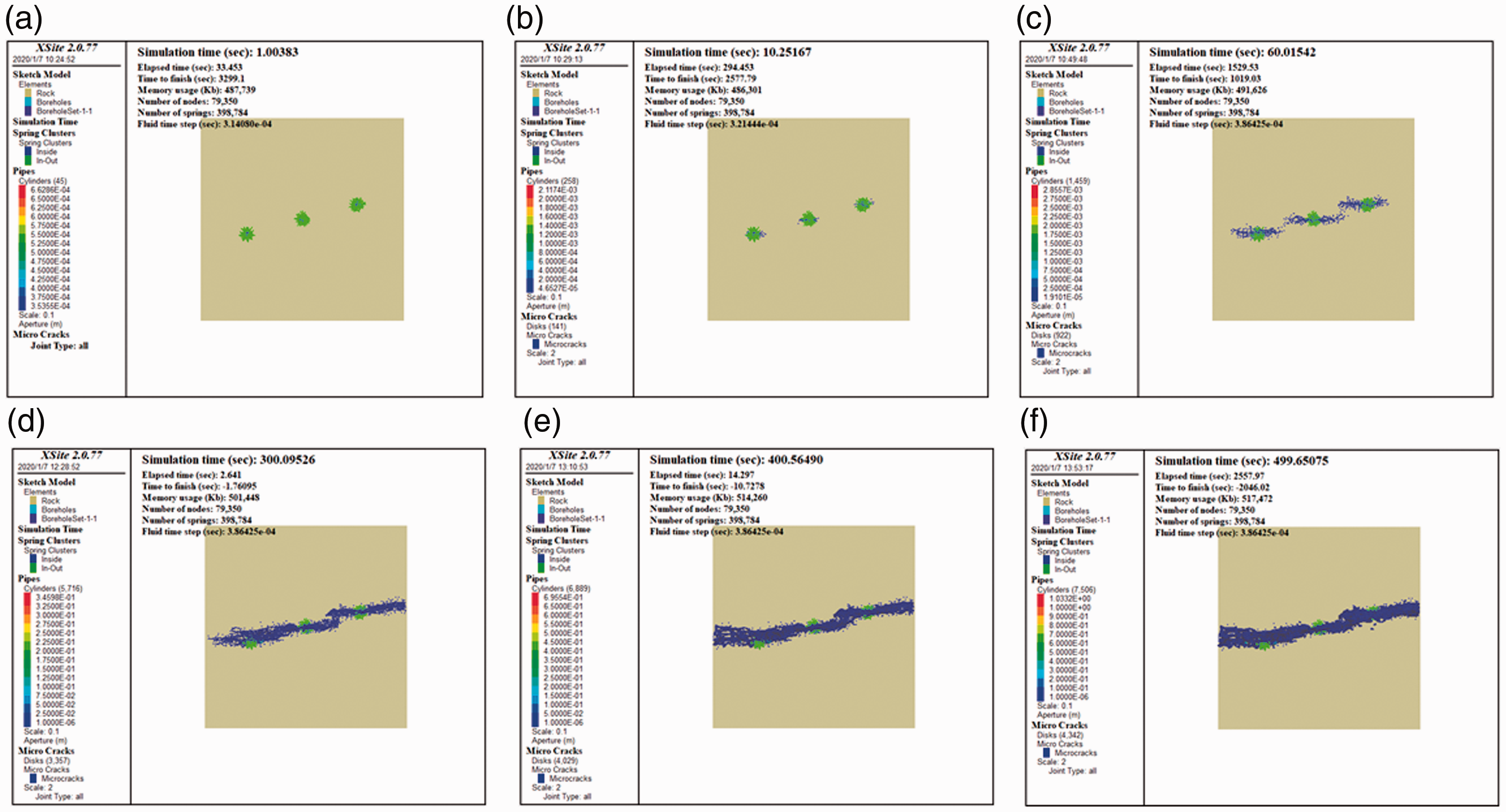
The initiation and propagation of multi-hole linear co-directional hydraulic fracturing. (a) t = 1 s; (b) t = 10 s; (c) t = 60 s; (d) t = 300 s; (e) t = 400 s; and (f) t = 500 s.
The net pressure, the difference in fluid pressure and the minimum in situ stress, maintain the opening of the fracture. With the injection of fracturing fluid, both the in-seam water pressure and the fracture width increase. During fracture propagation, the difference in fluid pressure and pore pressure provides power for fracturing fluid filtration, resulting in fluid filtration from the fracture surface to the surrounding rock. The rate of fracture propagation gradually slows down, which can be explained as follows: during water injection, the brittleness of the rock mass decreases and the plasticity increases. Some energy is released due to the generated fractures. When the energy has difficult accumulating in large quantities, rupture termination is reached, and the number of micro-fractures does not continue to increase over time.
Basic initiation and propagation laws of hydraulic fracturing
It can be seen from the results of the numerical simulation of multi-hole linear co-directional hydraulic fracturing (Figures 6 and 7) that, (1) before the of initiation of hydraulic fracture, the water pressure continues to increase. In this stage, there is no acoustic emission signal and there are no microcracks (Figures 6(a) and 7(a)). With the increase in water pressure, the three-dimensional fracture starts to rupture. Of course, there are micro-fractures and an acoustic emission signal at this stage (Figures 6(b) and 7(b)). The direction of initiation of the hydraulic fracture is along the maximum principal stress σ1, which is consistent with the general laws of hydraulic fracture initiation. (2) During the hydraulic fracturing experiment, the fracturing borehole is divided into a bare borehole section and a non-bare borehole section (Figure 3). The hydraulic fracture first breaks along the axial direction of the bare borehole. This phenomenon can be explained by the fact that the non-bare hole section is equipped with a hole-sealing device made of cast iron. The water pressure directly acts on the wall of the bare hole section and the inner wall of the hole sealing device. However, the tensile strength of the rock mass in the bare hole section is far less than that of the cast iron in the non-bare hole section. (3) Hydraulic fractures first break and expand around the section of the bare borehole. Then they extend into the rock mass corresponding to the non-bare borehole section, and finally, they extend into the rock mass without the borehole (Figure 7(c) and (d)). This process is well demonstrated by the results of the numerical simulation and, complements the limitations that cannot be directly shown by physical experiments. (4) The projection line of the hydraulic fracture network on the upper surface of the rock mass is basically extended and connected along the direction of the centre line of the borehole. There is a certain angle between the linear direction, where the projection is located, and the maximum principal stress σ1 (Figures 6(c) to (f) and 7(c) and (d)), indicating that, during fracture propagation, the hydraulic fracture steers to some extent from its initiation direction, which is the result of the redistribution of its surrounding ground stress induced by hydraulic fracture. Because a rock mass has a certain permeability, water has a certain filtration function in its interior. With the increase in the water pressure in the borehole, the borehole wall undergoes compression deformation. Such mutual compression between the boreholes results in tension stress perpendicular to the central line of the borehole. When multiple boreholes are arranged on the same straight line, the tensile stress of the borehole will be superimposed, and the tensile stress at the intersection point between the borehole centre line and the borehole wall will first reach the maximum value. When the tensile stress is greater than that of the rock mass, the rock mass begins to break. Water is eventually allowed to flow into the fracture and permeate the boundary area of the fracture tip. Through continuous water injection, the pore water pressure and matrix stress are also superimposed. Therefore, the stress distribution in the boundary region of the fracture tip will change, which helps the tensile fracture to steer and eventually expand along the centre line of the adjacent borehole. When the fractures around each borehole intersect and pass through each other, the tensile fractures connect in the direction of the borehole centre line. A directional failure plane along the direction of the borehole centre line is formed, and the directional expansion and penetration of the multi-hole linear col-directional hydraulic fracture is achieved. (5) Outside the range of the borehole, the hydraulic fracture expands along the centre line of the borehole. At the same time, it is affected by the boundary effect, which finally causes the fracture outside the range of the borehole to deflect towards the direction of the maximum principal stress σ1 to some extent.
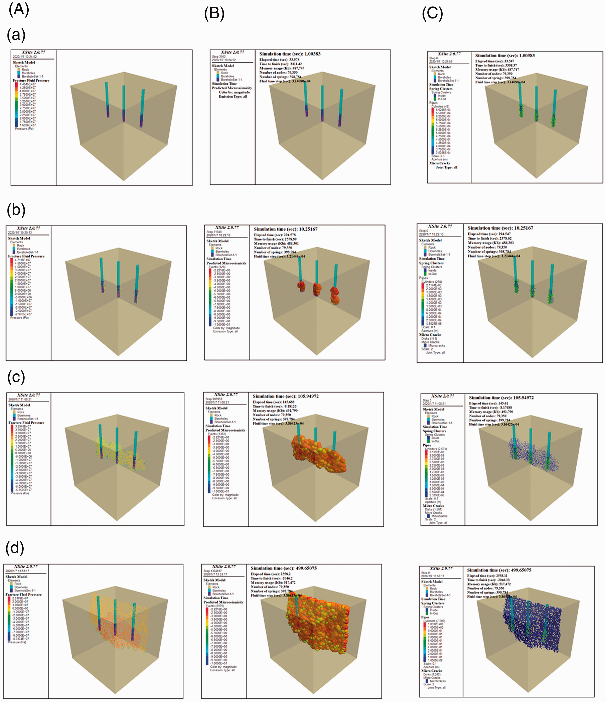
The process of multi-hole linear co-directional hydraulic fracturing. (a) Water pressure increase (t = 1 s); (b) initiation of hydraulic fracture (t = 10 s); (c) unstable propagation of hydraulic fracture (t = 106 s); (d) stable propagation of hydraulic fracture (t = 500 s). (A) Distribution of water pressure; (B) acoustic emission signal; and (C) three-dimensional hydraulic fracture network morphology.
Theoretical analysis of multi-hole linear co-directional hydraulic fracture connection
There are linear elastic, non-linear elastic and elastic-plastic models of rock mechanics, and the models can all be used to describe the stress distribution characteristics around the borehole. However, the linear elastic model has fewer parameters that are easier to determine, and these physical meanings of these parameters are specific. As a result, the linear elastic model is widely used. Thus, this model is utilized in this paper to study the mechanics of the initiation and propagation process of multi-hole linear co-directional hydraulic fracture.
Analysis on the initiation of the multi-hole linear do-directional hydraulic fracturing borehole
The formation of hydraulic fractures is mainly controlled by the rock mechanical properties of reservoirs and the stress state of the borehole. The state of in situ stress determines the mechanical properties and geometric morphology of hydraulic fractures. It is assumed that the borehole axis is aligned with the vertical ground stress, and the borehole is subjected to the maximum and minimum principal ground stresses σmax and σmin in the horizontal direction, respectively. Then, during hydraulic fracturing, with the increase in Pw in the borehole, a tensile stress zone will be induced on the wall of the borehole. When the tensile stress at a certain point exceeds the tensile strength of the rock, tensile failure occurs on the wall of the borehole, and hydraulic fractures will be formed in the direction of maximum principal ground stress σmax. The following assumptions are made: (1) the fracture propagates symmetrically in the direction of maximum principal ground stress σmax; and (2) the flow pressure Pf in the fracture is evenly distributed on its surface. Then, the simplified model of fracture initiation, which is shown in Figure 8, can be established.
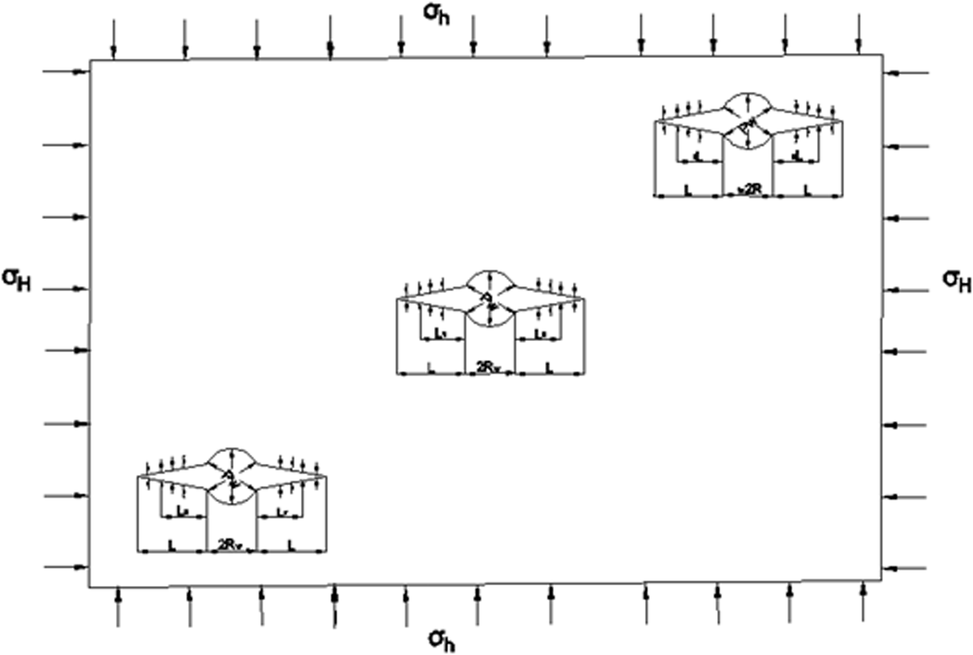
Fracture initiation model of multi-hole linear co-directional hydraulic fracturing.
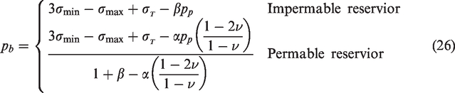
According to the elastic theory, the rupture pressure pb can be calculated as follows

Most of the rock mass has many pores through which fluid can flow. Due to the difference in fluid pressure between the fracture and the reservoir, the fracturing fluid flows from the fracture to the reservoir. This condition is also known as fracturing fluid filtration. During multi-hole linear co-directional hydraulic fracturing, the borehole pressure and the reservoir pressure (or pore pressure) are balanced. Thus, the fracture fluid will overcome the tangential compressive stress generated by ground stress around the wall of the borehole. Additionally, tensile stress will be generated around the wall of the borehole. When the tensile stress reaches the tensile strength of the rock mass, hydraulic fracture is initiated. The experimental results show that porosity and pore fluid have greatly influence the rupture of the rock mass.
According to the elastic theory of porosity, the calculation formula of rock fracture pressure is as follows
Stress field induced by multi-hole linear co-directional hydraulic fracture
In general, the hydraulic fracture propagates along the direction of the maximum principal stress. Along this direction, the hydraulic fracture is not affected only by the tensile stress, not shear stress. Assuming the fracture surface is affected by a uniform internal pressure and is free from any force at infinity, the physical model shown in Figure 9 can be utilized. In this model, a linear fracture in the centre of the plate can be regarded as the limit of an ellipse with a short semi-axis approaching zero. The length of the linear fracture is 2a. This fracture penetrates the plate, and the tension stress on the fracture surface is -p. The boundary conditions are as follows
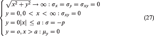
Physical model of the fracture under tensile stress.
If the direction of the fracture shown in Figure 9 is regarded as the height direction, i.e. the x-y plane is replaced by the x-z plane, then the stress transformation of a two-dimensional vertical fracture can be as shown in Figure 10.
Stress transformation diagram of a two-dimensional vertical fracture.
It can be concluded that the stress field induced by a two-dimensional vertical fracture is as follows
According to Hooke's law, the following calculation can be applied

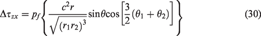
In formulae (28)–(31), the relationship between geometric parameters is as follows
If the values of θ, θ1 and θ2 are negative, then they should be replaced by the values of θ + 180°, θ1+180° and θ2+180°, respectively. Formulae (3)–(7) can be utilized to calculate the stress induced by the hydraulic fracture. The results of the theoretical calculation show that the induced stress decreases with the increase in the distance to the fracture surface. The horizontal stress perpendicular to the fracture which is induced by the fracture, is the largest, and the horizontal stress, along the fracture, which is induced by the fracture, is the smallest. The induced stress field is generated by the hydraulic fracture in the reservoir, and it is combined with the original stress. The additional induced stress perpendicular to the fracture is large, while the additional induced stress along the fracture is small. Therefore, it is possible to make the original minimum horizontal principal stress greater than the original maximum horizontal principal stress, which leads to the change in the stress state. With the increase in the distance to the fracture, the induced stress decreases rapidly, and the ground stress field remains in its initial state after a certain distance to the fracture.
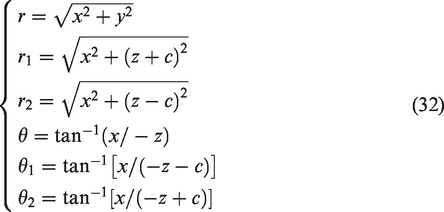
During multi-hole co-directional hydraulic fracturing, the stress field induced by the hydraulic fracture (Figure 11A(a) and B(a)) will induce the subsequent propagation of the hydraulic fracture. As a result, the minimum principal stress near the fracture will be deflected (Figure 11A(b) and B(b)). The direction of the minimum principal stress after deflection is basically perpendicular to the connected line of the deflection point of the main hydraulic fractures of the two adjacent boreholes. As a result, the main hydraulic fracture will propagate along the connected centre line of the fracturing boreholes, and they penetrate each other, as shown in Figure 11A(b), A(c), B(b) and B(c). The above laws can be verified by the numerical results (Figure 11) of RFPA and XSite.
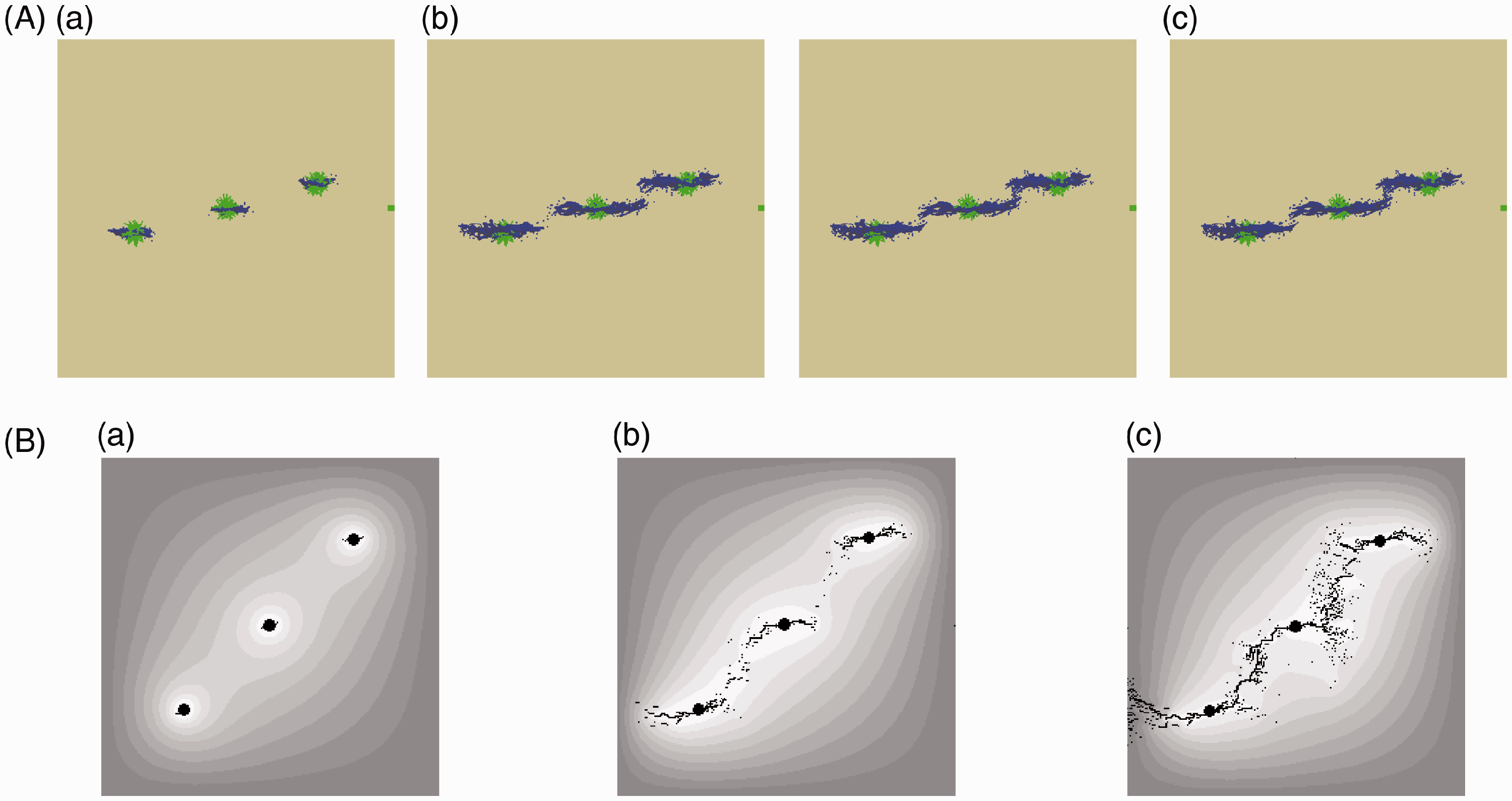
The initiation, propagation and penetration of multi-hole linear co-directional hydraulic fracture. (A) Results of numerical simulation by XSite software: (a) initiation of hydraulic fracture; (b) propagation of hydraulic fracture (deflection of the fracture direction); and (c) penetration of hydraulic fracture. (B) Results of numerical simulation by RFPA software: (a) initiation of hydraulic fracture; (b) propagation of hydraulic fracture (deflection of the fracture direction); and (c) penetration of hydraulic fracture.
Possibility analysis of connecting boreholes
To ensure the propagation of the hydraulic fracture, the extension pressure pf must be greater than the minimum principal stress to induce a tensile stress field at the leading edge of the fracture end and split the reservoir rock during fracture propagation. When the fractures expand relative to each other, the tensile stress field of the leading edge of the fracture ends will superimpose each other. After that, the fractures interact with each other and tend to expand relative to each other in the superimposed region of the tensile stress field at the leading edge of the fracture ends. As the fracture ends get close to each other, a strong tensile stress field will be formed in the superimposed region. As a result, the fracture will expand continuously and eventually connect with the boreholes. During multi-hole linear co-directional hydraulic fracturing, two relatively extended hydraulic fractures are close to each other and begin to interact with each other. After that, the stress field at the end of the fracture changes, which will affect the direction of fracture propagation. As a result, the change in the fracture propagation direction may be conducive to fracture intersection and increase the possibility of connectivity among boreholes.
Conclusions
In this paper, the basic law of multi-hole linear co-directional hydraulic fracturing is studied by using XSite software. The experimental results are as following:
The process of multi-hole linear co-directional hydraulic fracturing can be divided into four stages: water pressure increase, hydraulic fracture initiation, unstable propagation of hydraulic fracture and stable propagation of hydraulic fracture. When the water discharge is constant, the unstable and stable stage of propagation of hydraulic fracture can be compared. The latter stage lasts longer than the former, and microcracks generated in the latter stage are more than those in the former stage. Due to the existence of the borehole-sealing device, the three-dimensional hydraulic fracture first initiates and expands along the axial direction in the bare borehole section. Then, it extends along the axial direction in the non-bare hole section. Finally, it expands along the axial direction in the rock mass without a borehole. The stronger the acoustic emission signal in the middle of the adjacent borehole, the more microcracks are generated in the same part. The projection line of the hydraulic fracture network on the upper surface of the test block basically extends along the direction of the centre line of the borehole. There is an angle between the projection line and the direction of the maximum principal stress. It indicates that some degree of steering occurs during hydraulic fracture propagation, as a result of the redistribution of the ground stress. Outside the range between fracturing holes, the hydraulic fracture expands along the centre line of the borehole, and it is also affected by the boundary effect, which causes the hydraulic fracture at the boundary to deflect towards the maximum principal stress. During multi-hole linear co-directional hydraulic fracturing, two relatively extended hydraulic fractures are close to each other and begin to interact with each other. When the pressure of fracture propagation is greater than the minimum principle stress and the tension field is induced in the leading edge of the fracture end, the direction of fracture propagation will change. The change in the fracture propagation direction may be conducive to fracture intersection, increasing the possibility of connecting the boreholes.
Footnotes
Declaration of conflicting interests
The author(s) declared no potential conflicts of interest with respect to the research, authorship, and/or publication of this article.
Funding
The author(s) disclosed the following financial support for the research, authorship, and publication of this article: This work was supported by Transformation of Scientific and Technological Achievements Programs of Higher Education Institutions in Shanxi (TSTAP) (No. 2020CG050), Special Project of 2019 Plan for the Introduction of High-level Scientific and Technological Talents in Development Zone of Lvliang City (Development of automatic disassembly platform for hydraulic support pin shaft) (No. 2019102), Science and Technology Project of Lvliang City in 2019 (Pressure relief and permeability improvement technology by integrated hydraulic flushing and cutting for low permeability coal seam containing methane) (No. GXZDYF2019080) and Study on Technology of High-pressure Water Jet Assisted Hydraulic Fracturing Coupled Enhancing Permeability in Low Permeable and High Gas Coal Seam (No. Rc 2020–115), School-Level Teaching Reform and Innovation Projects of Luliang University in 2020 (No. JXGG202039) and Scientific and Technological Innovation Programs of Higher Education Institutions in Shanxi (STIP) (No. 2019L0938, 2019L0971 and 2020L0708).