
Abstract
To clarify the influence of pore pressure gradient on hydraulic fracture propagation, the stress distribution in and around the borehole is explained by theoretical analysis method in this paper. A mechanical model of hydraulic fracture initiation under the action of pore pressure gradient is established. Then coupled seepage-stress-damage software is used to simulate the initiation and propagation of hydraulic fractures in rock samples under the action of pore pressure gradient. Finally, the influence of the number and spatial position of the induction holes on the initiation and propagation of hydraulic fractures is analyzed. It is shown that: (1) Pore pressure gradient can effectively reduce the initiation pressure of hydraulic fractures. (2) The greater the pore pressure gradient is, the easier the hydraulic fracture is to spread to the region with high pore pressure. (3) With the action of pore pressure gradient, the hydraulic fracture is shaped as ‘丨’, ‘丿’ and ‘S’ types and can be represented by the four abstract conceptual models.
Keywords
Introduction
Many rocks of oil and gas reservoir, characterized with both pores and fractures, are dual-porosity and typical low-permeability medium (Cordero et al., 2019; Wang, 2018; Wang et al., 2018). Due to the pore pressure inside the rock, the mechanical properties are very complicated. The effective stress theory proposed by Biot is generally applicable to rock materials and makes the parameter of pore pressure widely used in the field of rock mechanics (Biot, 1941). For hydraulic fracturing, water pressure is mainly used to destroy macroscopic and microscopic structures of rock mass. Hydraulic fractures are generated in the rock mass to improve the permeability performance of the rock mass and weaken the strength of rock mass. When hydraulic fracturing is conducted, the influence of pore pressure field on the propagation process of hydraulic fractures cannot be ignored (Golovin and Baykin, 2016; Takatoshi, 2008). However, in the previous research on hydraulic fracturing of the rock mass, the shape of hydraulic fractures (or networks) and the initiation and expansion process of hydraulic fractures is mainly focused on, while the influence and mechanism of pore pressure gradient on hydraulic fracture were not deeply understood (Lu and He, 2020; Lu et al., 2020; Song et al., 2020). The study of the rock failure process under the action of pore pressure gradient is helpful to understand the initiation, expansion and connecting mechanism of water-bearing joints in the rock mass and to clarify the mechanism of the interaction between damaged fracture and seepage in rock mass.
In the early stage, it was believed that pore pressure did not affect the fracture toughness of rocks. It was found by the fracture tests conducted by Abousayed on Indiana limestone that the measurement of fracture toughness had nothing to do with pore pressure (Abousayed, 1978). However, it is also widely believed that pore pressure affects rock fracture (Gao et al., 2019a, 2019b). It was found by Robinson et al. that brittle or ductile failure of sedimentary rocks depends on the difference between internal pore pressure and external confining pressure (Robinson, 1959). It was found by the through rock plate rupture test that the initiation pressure and direction of hydraulic fracture was not only affected by the stress difference at the tip of hydraulic fracture but also affected by the size and gradient of the pore pressure. The increase of pore pressure at the fracture tip can lead to the propagation of the hydraulic fracture, while the change of pore pressure gradient may impede the extension of hydraulic fracture. That is to say; pore pressure has double function on the propagation of hydraulic fracture (Bruno and Nakagawa, 1991, Wang et al., 2013). It was believed by Muller that rock fracture toughness increases with the increase of effective confining pressure (the difference between confining and pore pressure) (Muller, 1986). In contrast, Huang et al. believed that, under the same confining pressure, the fracture pressure of hydraulic fracture increases with the increase of pore pressure (Huang et al., 2018). However, it was believed by Leng et al. that hydraulic fracture extension is not only affected by the magnitude of the local pore pressure at the fracture tip, at the same time, it is also controlled by macro pore pressure gradient distribution. And its initiation pressure decreases with the increase of local pore pressure (Agrawal et al., 2018; Altammar et al., 2017, 2018; Leng et al., 2003). Some scholars have studied the propagation rule of hydraulic fractures under the action of the symmetric or uniform pore pressure field, and then a hydraulic fracturing propagation model that considers pore pressure is proposed (Gao et al., 2019c; Gholami et al., 2017; Renshaw and Pollard, 1994). It is obtained from the results of non-uniform pore pressure field on the expansion rules of hydraulic fractures that the existence of pore pressure field can increase the stress intensity factor at the tip of hydraulic fractures, inducing the expansion of hydraulic fractures along the direction of high pore pressure (Li et al., 2015; Shou et al., 2015; Tang et al., 2003). The expansion of hydraulic fractures is not only affected by the local pore pressure at the fracture tip but also controlled by the macroscopic distribution of pore pressure gradient (Rahul et al., 2017). At the same time, the stress intensity factor at the tip of the hydraulic fracture increases with the increase of pore pressure. The greater the pore pressure is, the larger the deflection amplitude of the hydraulic fracture will be (Leng et al., 2003; Lu et al., 2016). At the same time, the pore pressure gradient also has an impact on the acoustic emission characteristics of coal and rock rupture (Pearson, 1981; Xu et al., 2004; Zhao et al., 2014).
The physical test of pore pressure gradient affecting hydraulic fracture propagation is time-consuming and laborious, and it is easy to be affected by some irrelevant factors in the test process. However, the numerical test has always been simple and convenient. In this paper, the calculation model of hydraulic fracture initiation pressure under pore pressure is first established. Then the physical experiment results were verified by the fluid-damage-stress coupled RFPA2D-Flow software. Finally, the process of hydraulic fracture initiation and propagation under the action of different pore pressure and influencing factors such as the number and spatial arrangement of the induced pores is simulated. The research results have some guiding significance for controlling the propagation of hydraulic fractures.
Mechanical model of initiation pressure of hydraulic fracture under the action of pore pressure gradient
The relationship between rock deformation and porosity, compressibility and volume modulus of elasticity during the process of pore pressure change is deduced by Liu Qi et al. Through theoretical calculation and analysis (Liu et al., 2008). It is found by Liu Xiangjun et al. through triaxial compressive tests that all of the triaxial compressive strength, elastic modulus, volume modulus and shear modulus of rocks increased with the decrease of pore pressure under the condition of constant confining pressure (Liu et al., 2011).
When hydraulic fracturing is carried out in the rock, the stress around fracturing borehole is influenced by the integrated action of the original rock ground stress and the water pressure p inside fracturing borehole. At the same time, it is also affected by the pore pressure generated from the water pressure pw inside the induced hole. The stress field in the local coordinate system of the rock mass around the fracturing borehole is shown in Figure 1. In Figure 1, σv is vertical geostress, and σh is horizontal geostress.
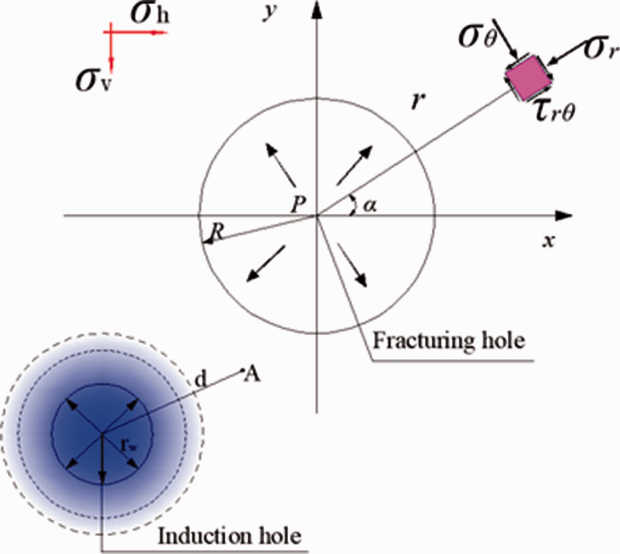
Stress distribution around the fracturing borehole under the action of pore pressure gradient.
According to the theory of elastic mechanics, with the pore pressure generated by the induced hole considered, the stress at any point in the coal and rock around the borehole is as follows:
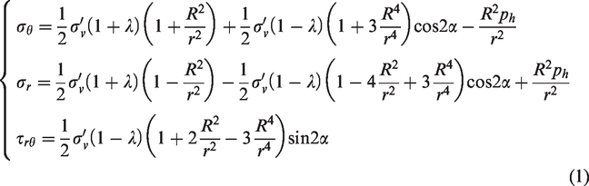
Where, ph is the water pressure in the fracturing hole; σθ, σr and τrθ is separately the tangential, radial and shear stress at any point in the rock mass around the fracturing borehole; σv’ is the effective vertical geostress; λ is the lateral coefficient; R is the radius of the fracturing borehole; r is the distance between any point in the rock mass and the centre of the fracturing borehole; α is the azimuth angle of any point in the rock mass around the fracturing borehole.
According to the theory of thick-wall plane radial flow, it is assumed that in the infinite formation, the induction hole is filled with stable and high-pressure water, and its influence range is represented with Re. The pressure distribution equation and boundary conditions at point A from the centre of the induction hole d can be written as follows (Cheng et al., 2020):
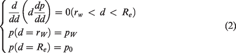
Where: rw is the radius of the induction hole; pw is the regulated water pressure of the induction hole; p0 is the original pore pressure in the rock mass.
According to formula (2), the pore pressure distribution at point A around the induced hole can be calculated as follows

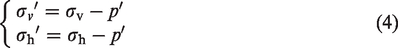
According to the effective stress principle, the stress in the vicinity of the fracturing hole will be changed within the influence range of the pore pressure gradient generated by the induction hole. Pore pressure has no effect on shear stress but normal stress. Therefore, the formula for calculating the normal stress in Equation (1) is as follows
According to the theory of tensile failure, when the fracture causing hole wall is destroyed, the following conditions should be met for the fracture initiation of the wall of the fracturing borehole

Ignoring the sign of tensile and compressive stress, when the shear stress reaches the tensile strength of the rock, fracture starts to initiate. Connecting formula (1) to formula (5), it can be obtained that the critical initiation pressure at different spatial positions in the rock mass under the action of pore pressure gradient is as follows
According to the formula (6), pore pressure gradient can reduce the critical initiation pressure phcri of the hydraulic fracture. The decreased amplitude of phcri is positively correlated to the water pressure pw in the induction hole and negatively correlated to the distance d between the fracturing and induction hole. When the water pressure pw of the induction hole is larger, the value of d is smaller, and the decrease amplitude of the initiation pressure phcri is larger. On the contrary, the smaller the water injection pressure pw is, the larger the value of d is, and the smaller the decreased amplitude of the initiation pressure phcri is.
Numerical verification of the effect of pore pressure gradient on hydraulic fracture propagation
Introduction of RFPA2D-Flow software
In this paper, RFPA2D-Flow software, a seepage-stress coupling analysis system for rock fracture instability, is used to the influence of pore pressure gradient on hydraulic fracture propagation based on the damage mechanics theory, in which both tensile and shear failure criteria of the rock are chosen. A detailed introduction on the calculation principles of this software can be found in many literatures (Li et al., 2011; Lu et al., 2020).
Geometric model
In this numerical experiment, a two-dimensional plane strain seepage model (Figure 2) with a size of 100 mm×200 mm is adopted, and it is divided into 200 × 400 cells. The left and right boundary of the model is free, and the lower is fixed. The external force exerted on the upper is 4 MPa, and all four boundaries are impermeable. In this model, two circular holes are arranged. The borehole No. 1 is the fracturing hole, and its coordinate of the centre of the circle is (50 mm, 125 mm). The borehole No. 2 is the induction borehole, whose water pressure is constant and results in inducing fracture expansion of hydraulic pressure. The centre of the circle is at the point (30mm, 75mm). Both radius of the borehole is all 6 mm. The initial water pressure in the No.1 fracturing hole is 4 MPa, and increment for each step was 0.2 MPa. Constant water pressure is applied in No. 2 induction holes, and the water pressure is 0 MPa, 1 MPa, 2 MPa, 3 MPa and 4 MPa, respectively.
Geometric model.
Comparison of numerical calculation and physical experiment results. (a) Results of the numerical simulation; (b) Results of experimental test.
Parameters selection
To ensure that the numerical calculation can more closely simulate the real physical experiment, the real physical parameters of the experimental sample are adopted in the numerical simulation as much as possible. The parameters, such as compressive strength, can be obtained by mechanical test, and internal friction angle can be calculated. And then the stress-strain curve can be obtained. Moreover, the residual strength coefficient, the maximum tension and compressive strain coefficient, and the elastic modules, are very easy to obtain. The permeability can be obtained by the laboratory experiment. The relevant parameters used in this numerical simulation are shown in Table 1.
Numerical simulation parameters.
Verification of the effect of pore pressure gradient on the process of the hydraulic fracture propagation
The comparison of numerical calculation and physical experiment results is shown in Figure 3. When there is no water inside the induction hole, the hydraulic fracture propagates along the vertical direction, which is consistent with the theory that the hydraulic fracture expands along the maximum principal stress. When the water pressure of the induction hole is 1 MPa, the hydraulic fracture tends to propagate towards the induction hole, but it does not pass through the induction hole and still expands downward. When the water pressure of the induction hole is increased to 2 MPa, the hydraulic fracture has passed the edge of the induction hole and continued to expand downward. When the water pressure in the induction hole is increased to 3 MPa, the hydraulic fracture passes through the induction hole and continues to expand. When the water pressure reaches 4 MPa, the hydraulic fracture deflects to the left side of the specimen after passing through the induction hole. When the water pressure in the induction hole increases from 0 MPa to 4 MPa, the water pressure in the induction hole has a significant influence on the expansion of the hydraulic fracture, and the amplitude of the deflection of the hydraulic fracture is directly related to the water pressure in the induction hole. With the increase of the water pressure in the induction hole, the deflection amplitude of the hydraulic fracture becomes larger and larger (Lu et al., 2016). This is consistent with the experimental results of Lu et al.
Both numerical calculation and physical test results (Figure 3) show that the non-uniform pore pressure field formed by the induction hole affects the propagation of hydraulic fractures. This can be explained by the fact that the existence of induction hole leads to the stress increase at the tip of the hydraulic fracture, so the hydraulic fracture tends to expand in this direction more easily.
Rules of hydraulic fracture propagation under the action of pore pressure gradient
The evolution process of rock micro-fracture induced macro failure under the action of different water pressure fields is shown in Figure 4. For the numerical model in this paper, the water pressure can be transferred into the crack along the hydraulic fracture, so obvious stress concentration phenomenon at the inner wall of fracturing hole and the guiding fracture tip is produced under the action of initial water pressure. With the increase of water pressure, the stress accumulation becomes more and more obvious, and a ring zone of pressure increase is formed in several grid units along the edge of the fracturing hole. As the water pressure continues to increase, scattered micro-fractures occur at the tip of the guiding fracture (Figure 4(a)). Hydraulic fracture initiates along the guiding fracture tip. It can be seen from Figure 4(a) that the stress concentration at the guiding fracture tip is very obvious. Once the hydraulic fracture begins to initiate, the hydraulic fracture begins to expand with a small increase in the water pressure, and the rock comes to the stage of instability and failure. No matter how the water pressure changes in the induction hole, the newly generated hydraulic fractures in the upper part of the fracturing hole and the symmetrical position of the guiding fracture all expand vertically along the vertical direction, which is consistent with the experimental phenomenon of single-hole hydraulic fracturing without induction borehole. When the water pressure in the 2# hole is 0, the newly generated hydraulic fracture in the lower part of the 1# hole extends vertically along the guiding fracture. However, when the water pressure in 1# hole is 1MPa, 2 MPa, 3 MPa and 4 MPa, respectively, hydraulic fracture at the lower part of the 1# hole is no longer vertically scaling down in the direction of the guiding fracture (Figure 4(b)), but gradually deviates to the 2# hole (Figure 4(c)). As a result, a big macroscopic fracture is produced in the rock mass, leading to the complete rupture of the rock mass. When the water pressure is 3 MPa and 4 MPa, the hydraulic fracture is connected with the 2# hole. At the same time, from the perspective of fracture morphology of rock failure, the fracture surface is rough, the expansion path of hydraulic fracture is irregular, and it is accompanied with bifurcation behaviour (Figure 4(a) to (c)).
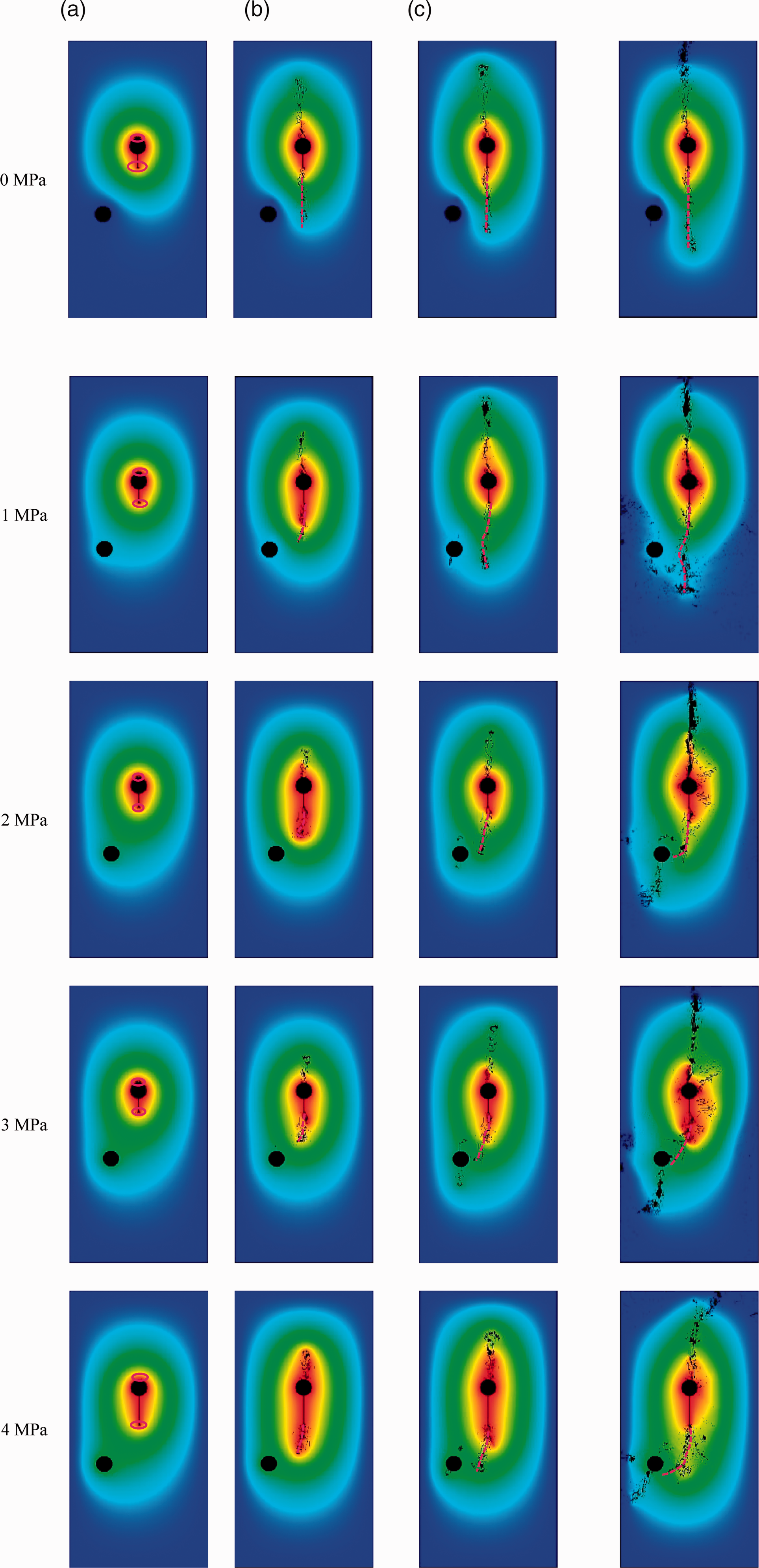
The morphology of hydraulic fracture propagation and distribution of pore pressure under different water pressure fields. (a) Initiation; (b) Propagation; (c) Deflection.
Five groups of numerical tests are carried out under different water pressure conditions. The constant water pressure in the 2# induction hole is adjusted during the test. It is shown by all the numerical test results (Figure 5) that the hydraulic fracture gradually steers to the induction hole after it begins to initiate along the guiding hole. The greater the constant water pressure in 2# induction hole, the stronger the deviation trend of hydraulic fracture to the 2# induction hole. This is consistent with the physical test results obtained by Lu et al. (2016). The pore pressure field formed by 1# fracturing hole and 2# inducing hole has an obvious control effect on the propagation direction of hydraulic fractures. Due to the self-organizing behaviour of hydraulic fractures, hydraulic fractures tend to expand perpendicular to the direction of the minimum principal stress to reduce the energy required for expansion. The water pressure in 2# induction and 1# fracturing holes act together, so the maximum tensile stress in the direction of the connection line of 1# and 2# holes is easily generated, resulting in the biased expansion of the hydraulic fracture.
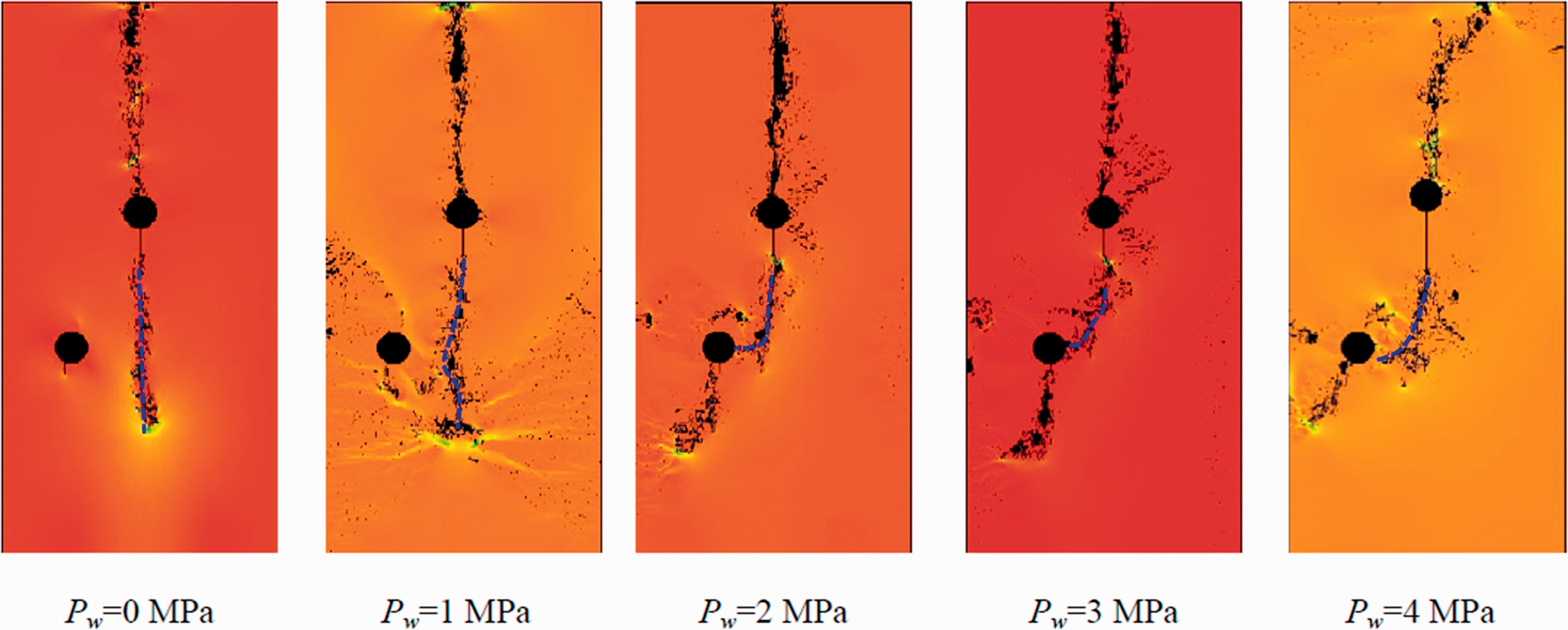
Minimum principal stress and spatial morphology of hydraulic fracture under different water pressure.
It can be seen from Figure 6 that the initiation pressure of hydraulic fractures decreases gradually with the increase of pore pressure. This is consistent with the analysis results of the mechanical model of fracture initiation pressure under the action of pore pressure gradient in Part 2.
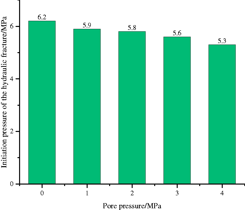
Initiation pressure of hydraulic fracture under different pore pressure.
Influencing factors of hydraulic fracture propagation under the action of pore pressure gradient
Number of induction holes
A different number of induction holes (constant water pressure is 2 MPa) are arranged along a straight line to observe their influence on the expansion morphology of hydraulic fractures, which is shown in Figure 7. When there is no induction hole, the hydraulic fracture extends vertically along the direction of the maximum principal stress (Figure 7(a)). With the appearance of the induction hole, the hydraulic fracture gradually deflects towards the direction of the induction hole. The more the number of the induction holes, the more obvious the deflection of the hydraulic fracture expands towards the line of the centres of the induction holes (Figure 7(b) to (d)). This can be explained by the fact that with the increase of the water pressure of the fracturing hole, there is a pressure difference between the fracturing and induction holes. Moreover, a pore pressure field is formed around the induction and fracturing holes. At the same time, there is a pore pressure gradient between the induction and fracturing hole due to the existence of the water pressure difference. The tip of the hydraulic fracture deflects in the direction of the pore pressure gradient. It is indicated that the expansion of hydraulic fractures is not only affected by the local pore pressure at the fracture tip but also affected by the macroscopic gradient distribution of pore pressure. In the expansion direction, hydraulic fractures expand toward the region with high pore pressure. When the direction of water flow is consistent with the path of hydraulic fracture expansion, the expansion of the hydraulic fracture will be promoted. When the direction of the pore pressure gradient is opposite to the direction of hydraulic fracture expansion, the water flow impedes the expansion of the hydraulic fracture.
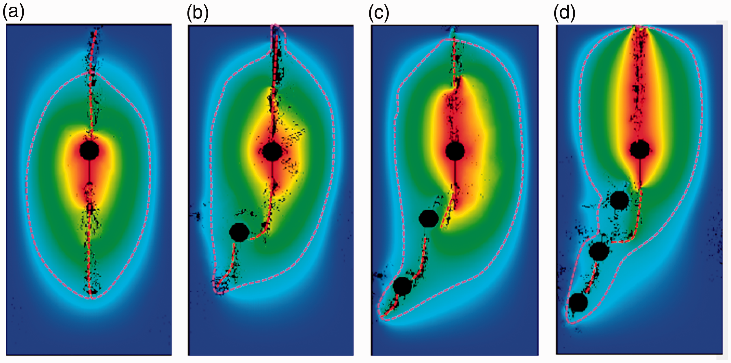
Pore pressure distribution and fracture propagation morphology with different number of induction holes. (a) No induction hole; (b) A single induction hole; (c) Double induction holes; (d) Three induction holes.
Spatial position of the induction holes
By changing the spatial position of the induction hole with constant water pressure, the induction holes are placed in symmetric and asymmetric positions. The spatial morphology of hydraulic fractures under the action of the pore pressure field generated by different borehole arrangements is shown in Figure 8. The water pressure pw2 and pw3 is constant, which is shown in Figure 8(a) to (c). The distance between left and right borehole is also constant. So, the pore pressure gradient is equal to the quotient of the pressure difference between pw2 and pw3 and the distance. Further, by combining Figure 8(a) to (c), the variation curve of deflection distance of hydraulic fractures with pore pressure gradient can be drawn, as shown in Figure 9.
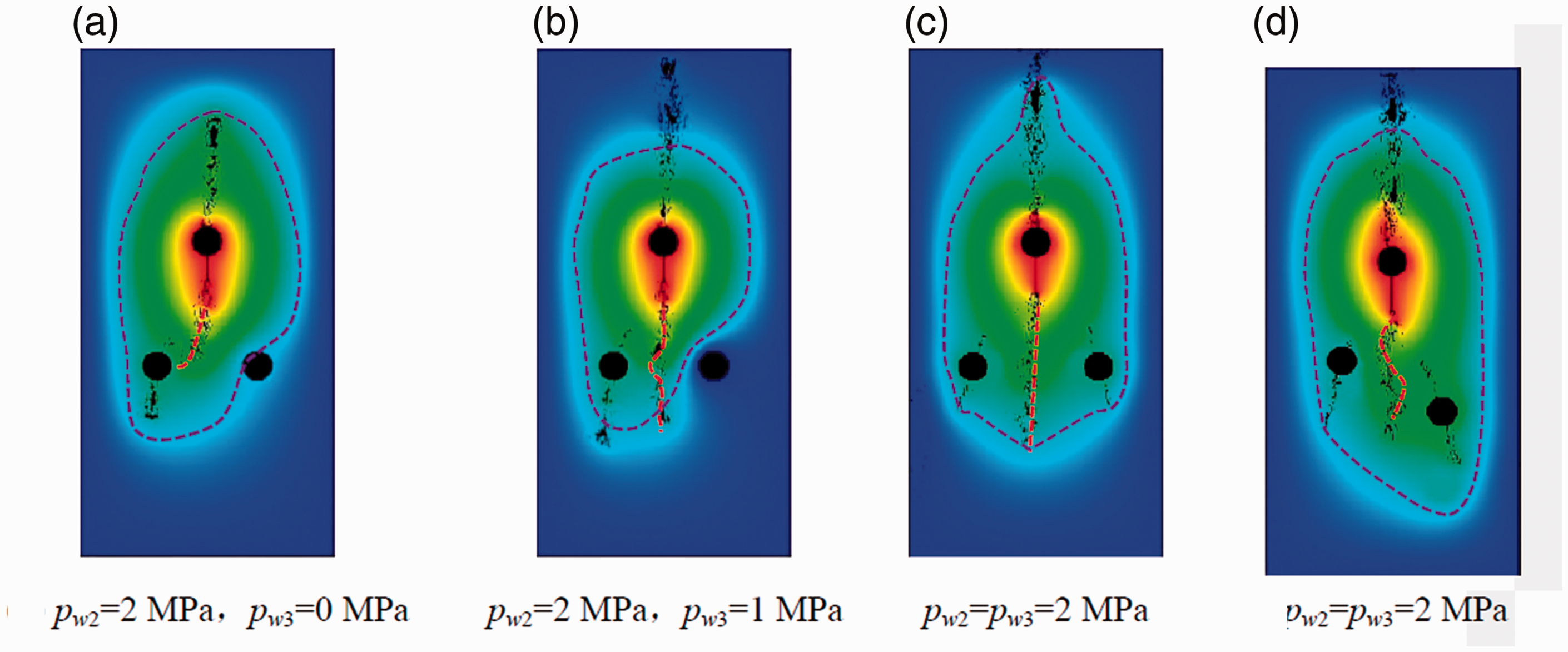
Spatial morphology of hydraulic fractures with the action of pore pressure field under different boreholes’ arrangements.
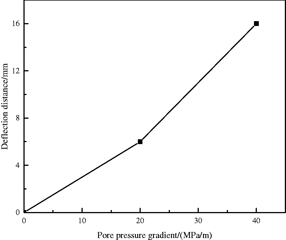
Variation curve of deflection distance of hydraulic fracture with the pore pressure gradient.
Comparing the spatial morphology of hydraulic fractures between Figure 8(a) to (c), the greater the pore pressure gradient difference between the two induction holes arranged symmetrically, the more likely the hydraulic fractures are to deflect towards the region with high pore pressure gradient. This pattern can be seen more intuitively in Figure 6.
Compared with the ‘丿’ shape in Figure 8(c), the ‘S’ shape in Figure 8(d) is obvious. The difference between them lies in the different spatial positions of the induction holes. During the process of hydraulic fracture propagating along the vertical direction, it is firstly influenced by the pore pressure gradient around the 2# induction hole, resulting in the fracture deflection towards to the induction hole. When hydraulic fracture passes through the influencing range of the 2# induction hole, hydraulic fracture again extends in the direction of the maximum principal stress and is presented as a ‘(’ shape. Similarly, the expansion of hydraulic fracture is also affected by the pore pressure gradient of the 3# induction hole. As a result, hydraulic fracture is presented of ‘)’ shape, which is the same shape as that of 2# induction hole. Finally, the overall shape of the hydraulic fracture is shown as ‘S’ shape.
Conceptual model of pore pressure gradient affecting hydraulic fracture propagation
Based on the rule of pore pressure gradient affecting hydraulic fracture propagation revealed by numerical simulation tests, the influence of pore pressure gradient on hydraulic fracture propagation can be abstracted into four models: (1) Mode I: The two induction holes with constant water pressure are arranged symmetrically. When the constant water pressure in the induction hole is equal, the hydraulic fracture expands along the direction of the maximum principal stress and presents a ‘丨’ shape, as shown in Figure 10(a). (2) Mode II: The two induction holes with constant water pressure is arranged symmetrically. When the constant water pressure inside the 2# induction hole is greater than that inside the 3# induction hole, the hydraulic fracture deviates toward the direction of the pore pressure gradient, then expands along the direction of maximum principal stress, presented as a ‘丿’ shape, as shown in Figure 10(b). (3) Mode III: The two induction holes with constant water pressure are arranged on the same side. When there is a constant water pressure, which is not zero, in the 2# and 3# induction holes, the hydraulic fracture always deviates toward the direction of the pore pressure gradient. It then expands along the direction of the maximum principal stress, presented as the ‘丿’ shape, as shown in Figure 10(c). (4) Mode VI: The two induction holes with constant water pressure are asymmetrically arranged in two sides. When there is a constant water pressure, which is not zero, in the 2# and 3# induction holes, hydraulic fracture firstly deflects offset toward the pore pressure gradient produced by the 2# induction hole and then deflects offset toward pore pressure gradient produced by the 3# induction hole. Finally, it expands along the direction of the maximum principal stress, presented as an ‘S’ shape, as shown in Figure 10(d).
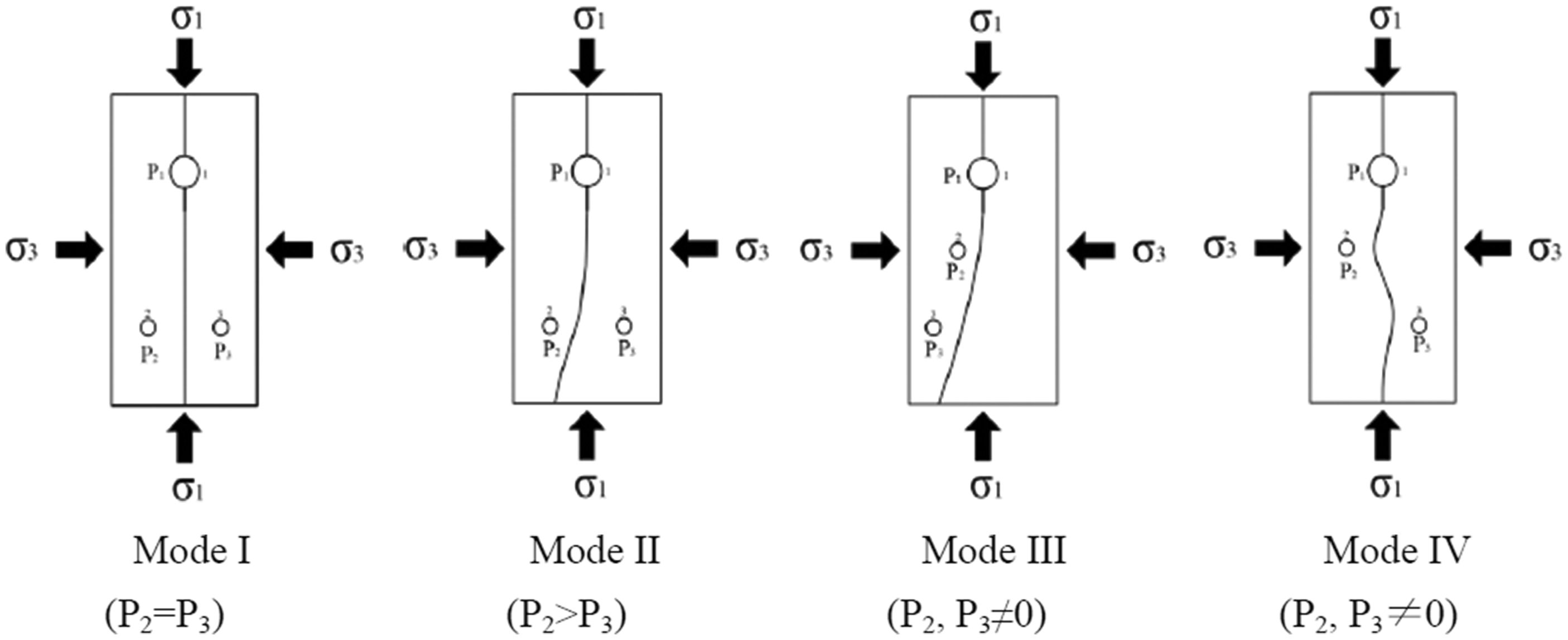
Conceptual model of pore pressure gradient affecting the spatial morphology of hydraulic fracture.
Conclusions
The influence of the pore pressure gradient generated by the induction hole on the stress distribution around the fracturing hole is analyzed. The mechanical model of the hydraulic fracture initiation pressure effected by the pore pressure gradient is established. It is shown by the analysis results of the mechanical model that the pore pressure gradient can effectively reduce the initiation pressure of the hydraulic fracture. The expansion of hydraulic fractures is mainly controlled by the tensile failure caused by the minimum principal stress. The local pore pressure is conducive to the formation of hydraulic fractures. The expansion of hydraulic fractures is affected not only by the local pore pressure at the fracture tip but also by the macroscopic distribution of pore pressure gradient. In the expansion direction, hydraulic fractures expand toward the region with high pore pressure. The greater the pore pressure gradient, the greater the deflection distance of the hydraulic fracture towards the high pore pressure zone. Different number and spatial arrangement of the induction holes can generate different pore pressure gradient. The hydraulic fracture is shaped in several spatial forms of ‘丨’, ‘丿’ and” ‘S’ shape. On this basis, four different conceptual models of pore pressure gradient affecting the propagation of the hydraulic fracture are abstracted.
Footnotes
Declaration of Conflicting Interests
The author(s) declared no potential conflicts of interest with respect to the research, authorship, and/or publication of this article.
Funding
The author(s) disclosed receipt of the following financial support for the research, authorship, and/or publication of this article: This work was supported by Transformation of Scientific and Technological Achievements Programs of Higher Education Institutions in Shanxi (TSTAP) (No. 2020CG050), Special Project of 2019 Plan for the Introduction of High-level Scientific and Technological Talents in Development Zone of Lvliang City (Development of automatic disassembly platform for hydraulic support pin shaft) (No. 2019102), Science and Technology Project of Lvliang City in 2019 (Pressure relief and permeability improvement technology by integrated hydraulic flushing and cutting for low permeability coal seam containing methane) (No. GXZDYF2019080) and School-Level Teaching Reform and Innovation Projects of Luliang University in 2020 (No. JXGG202039).