
Abstract
The bedding plane effect will occur when hydraulic fractures propagate to the bedding plane in sedimentary strata, resulting in the “≠,” “工,” or “/” shaped fracture morphology. Based on previous physical experiments results, this article analyzed the mecroscopic propagation mechanism of tensile failure and the mechanical conditions for main hydraulic fracture and the bedding plane fracture propagating, proposing the criteria for hydraulic fracture to penetrate through the bedding plane. A fully three-dimensional model of hydraulic fracture morphology in horizontal borehole hydraulic fracturing is established with the vertical water flow, water leak-off, and bedding plane effect taken into consideration. Basic equations of continuity, pressure decline, hydraulic fracture morphology, and others are solved. After that, true triaxial hydraulic fracturing experiments with samples containing bedding planes are conducted to verify the aperture, length, width, and height of hydraulic fractures in this model. The model is proved to be accurate and reliable.
Keywords
Introduction
The structural transformation of coal and rock matrix relates to many difficult problems including stimulated extraction of oil and shale gas, controlling the hard roof of coals, prevention of rockburst, stimulated extraction of gas in low penetration coal seams, and prevention of outburst of gas and coal. The morphology of hydraulic fracture is a key factor affecting the effect of hydraulic fracturing and, therefore, must be controlled (Huang, 2010; Huang et al., 2011). Reservoirs of oil, shale gas, and coalbed methane and the strata in coal mine are usually sedimentary rock with horizontal and layered structure. Visible coal–coal, rock–rock, and coal–rock interfaces, which are referred to as bedding planes, exist in the above sedimentary strata. Field tests show that interface effect will occur when the hydraulic fracture propagates to the bedding plane (Blair et al., 1989; Chen and Chen, 1997; Daneshy, 1978). The bedding plane has a significant effect on the morphology of hydraulic fractures (Chen and Chen, 1997). Study of the interface effect on hydraulic fracturing is of great importance to control hydraulic fractures propagation in specific rock strata.
Field investigation shows that bedding planes are tightly closed with low aperture, smooth wall, and low roughness. The fillers within the bedding plane are little and the interlayer spacing is large. The failure mode of bedding plane fracture is tensile failure, which belongs to the type I failure mode in fracture mechanics.
When the hydraulic fracture intersects with the bedding plane perpendicularly, the fracturing water will first flow within the bedding plane. Later the hydraulic fracture will penetrate through the bedding plane and extend along its original direction (Blair et al., 1989). Weak interface will prevent hydraulic fractures propagating along its original direction, while strong interface will not. However, the propagation law of hydraulic fractures will not change as the property of the two formations of the weak interface changes (Daneshy, 1978). Hydraulic fractures will penetrate natural fissures and propagate along its original direction only when the stress difference is high and the approaching angle is large. In most cases, hydraulic fracture will stop propagating or turn after intersecting with natural fissures (Blanton, 1982, 1986; Thiercelin et al., 1987). Quantitative researches show that the horizontal stress difference and the approaching angle have great impact on the open and the shear failure mechanics of natural fissures (Zhou et al., 2007, 2008, 2010). Hydraulic fractures can penetrate the interface directly or propagate along the bedding plane, which depends on the difference of the mechanical property of the production formation and the interlayer (Zhou et al., 2008), the interface property, the vertical compressive stress difference (Anderson, 1981; Biot et al., 1983; Chen and Chen, 1997; Warpinski et al., 1980, 1982), and the horizontal stress difference (Chen et al., 2008). The stress difference that prevents the propagation of hydraulic fractures is affected by the water pressure, fracture geometry, and fluid loss (Teufel and Clark, 1984; Warpinski et al., 1980).
Complex numerical model of hydraulic fracturing in natural reservoir has been developed by researchers (Weng, 2015). The stress intensity factor of hydraulic fractures propagating in layered strata has also been calculated (Zhao and Chen, 2010). Criteria for fracture penetrating through the bedding plane are developed (Biot et al., 1983), simple criteria to predict whether the hydraulic fracture will penetrate nonorthogonal natural fissures are derived (Gu et al., 2012), and criteria for hydraulic fracture to penetrate through natural fissures in the three-dimensional space are established (Cheng et al., 2014). Currently, there are two methods to calculate the size of two-dimensional fracture: the PKN model and the KGD model. The PKN model is based on the theory of vertical plane strain, while the KGD model is derived from horizontal plane strain (Chen et al., 2008). The fracture height is assumed to be constant in both PKN and KGD model. However, the fracture extends in the height direction to some extent. Therefore, four types of pseudo-three-dimensional models are developed. In these models, the hydraulic fracture is assumed to propagate with the shape of ellipse, and the variation of fracture height is taken into consideration. To simulate the three-dimensional fracture geometry, two methods are used: one is adopting the fracture propagation criterion (K = KIC) to introduce the fracture height into the model, the other is describing the fracture extension in the vertical direction by the KGD model while describing the horizontal propagation by the PKN model. The common features of the pseudo-three-dimensional models are as follows: the three-dimensional flow in the fracture is simplified into two- or one-dimensional flow because the fracture length is larger than its height. The vector water flow parallel to the fracture surfaces is not considered and the water loss is ignored. The difference between elastic modulus and fracture toughness of different formations is not considered. The calculation model for hydraulic fracture morphology in layered strata is studied. Calculation methods for fracture strength factor are discussed (Chen et al., 1994). From the perspective of fracture toughness, the vertical extension height of hydraulic fractures is calculated and then the mechanism of hydraulic fracturing is systematically studied. Based on the basic equations of elasticity, a three-dimensional model of hydraulic fractures in layered medium is derived and numerically solved. Then a fully three-dimensional fracture propagation model is proposed to simulate the hydraulic fracturing more closely. In the fully three-dimensional model, the vertical and horizontal extensions are separately simulated. In this model, the geometrical morphology, three-dimensional deformation, and two-dimensional water flow within hydraulic fractures are more closely reflected. Internationally, a simple and practical set of models are established to predict fully three-dimensional hydraulic fracture (Bouteca, 1984), and a coupling model of three-dimensional hydraulic fracture propagation and two-dimensional proppant transportation is developed (Lee and Jantz, 1989). In China, a fully three-dimensional model of hydraulic fractures under nonuniform conditions is established, and the calculation method of fracture width is given out (Chen and Chen, 1997; Chen et al., 1995). The present study suggests that bedding planes have great influence on the propagation of artificial hydraulic fractures. However, the study of propagation law of hydraulic fractures under three-dimensional conditions is not sufficient. Further studies should be conducted on this problem.
Previous experiments have been conducted with samples containing prefabricated bedding planes using the true triaxial hydraulic fracturing experiment system. On the basis of previous experiments, the basic form, three-dimensional conceptual model and three behavior types the “≠” shaped hydraulic fracture are revealed (Huang and Liu, 2017). In this work, based on the previous experiments, a fully three-dimensional propagation model for multihydraulic fractures is derived with the water loss, vertical water flow, and bedding plane effect taken into consideration.
Development of the mechanical model of hydraulic fracturing in horizontal strata borehole
Fully three-dimensional propagation model of hydraulic fractures
At present, good effects are usually achieved in exploitation of coalbed methane and oil by hydraulic fracturing with horizontal borehole (Figure 1(a)). When hydraulic fractures generated in horizontal borehole propagate to the bedding plane, it may propagate both within the bedding plane with the shape of ellipse and penetrate the bedding plane vertically, forming “≠” shaped fractures (Figure 1(b)). To describe the morphology of the main hydraulic fracture and the hydraulic fracture within the bedding plane (which is referred to as bedding plane fracture) more precisely, a three-dimensional coordinate system (Figure 1(b)) is established. The center of the unsealed section of the borehole at the bottom of the borehole is taken as the origin of the coordinate. In the vertical direction, the origin of the coordinate is located in the center between the two bedding planes. The x-axis of the coordinate is along the axial of the borehole, the y-axis is along the height of the main hydraulic fracture, and the z-axis is along the vertical direction. The model consists of three layers, i.e. the upper, middle, and bottom layer (Figure 2(a) and (b)), which represent the fracturing layer, roof layer, and floor layer.
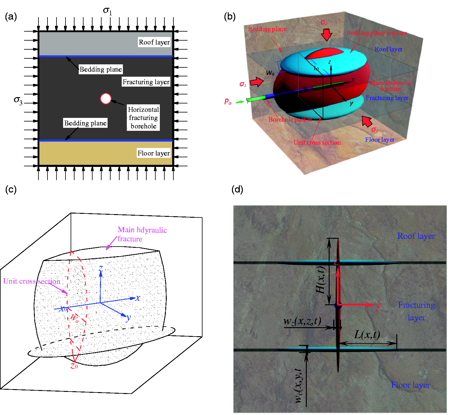
Fully three-dimensional model for hydraulic fractures morphology in hydraulic fracturing in horizontal borehole in rock strata. (a) Horizontal fracturing borehole, (b) three-dimensional propagation morphology of hydraulic fractures in strata (Huang and Liu, 2017), (c) subdivision of the hydraulic fracture by unit plane along the x-axis, and (d) parameters to describe the hydraulic fracture in cross section.
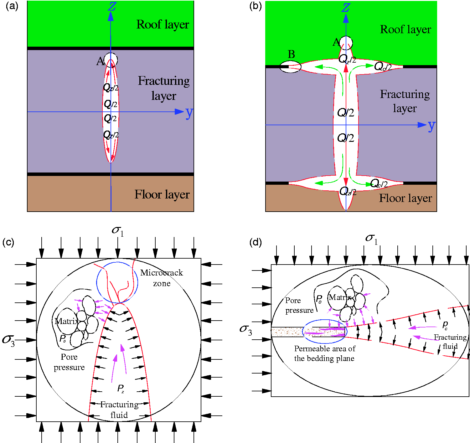
Mechanical model of the growth of the main hydraulic fracture and the bedding plane fracture. (a) Geometry of the main hydraulic fracture before intersecting with the bedding plane, (b) geometry of hydraulic fractures after the main hydraulic fracture intersects with the bedding plane, (c) stress state of the zone A at the tip of the main hydraulic fracture, and (d) stress state of the zone B at the tip of the bedding plane fracture.
To study the aperture, propagation direction, and range of hydraulic fractures, subdivide the hydraulic fracture into n cross sections by a series of planes that are perpendicular to the x-axis (Figure 1). The parameters to describe the hydraulic fracture in each plane include the aperture of the hydraulic fracture,
Propagation criteria for the main hydraulic fracture tip without bedding plane
Before the main hydraulic fracture intersects with the bedding plane (Figure 2(a)), the fracture tip is subject to principal stresses
Propagation criteria for hydraulic fracture tip with bedding plane
At the intersection of the hydraulic fracture with the bedding plane, fractures exist both in the direction of the main hydraulic fracture and in the bedding plane (Figure 2(b)). The stress state of the main hydraulic fracture tip is almost the same before and after intersection with the bedding plane. The tip of the bedding plane fracture is subject to the principal stress
Criteria for hydraulic fracture penetrating through the bedding plane
True triaxial experiments of hydraulic fracturing have proved that three types of propagation behaviors and shapes of hydraulic fracture may occur after the main hydraulic fracture intersects with the bedding plane: propagating along the bedding plane (with hydraulic fracture of “工”), penetrating through the bedding plane (with hydraulic fracture shape of “/”), or both the above two cases occur at the same time (with hydraulic fracture of “≠”) (Huang and Liu, 2017) (Figure 3).
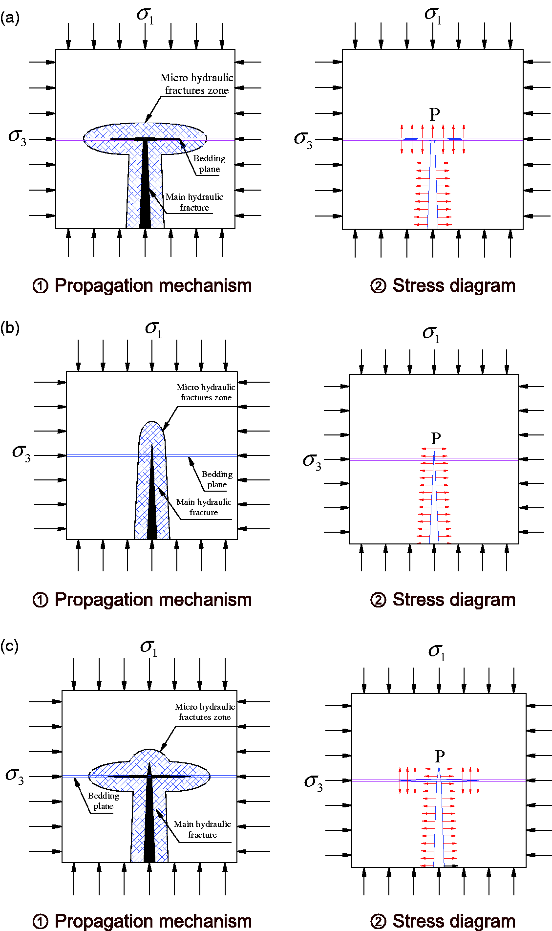
Propagation behavior models of hydraulic fractures after intersecting with the bedding plane. (a) Model I: hydraulic fracture propagates along the bedding plane, (b) Model II: hydraulic fractures propagate along the bedding plane and penetrate through the bedding plane at the same time, and (c) Model III: hydraulic fracture penetrates through the bedding plane.
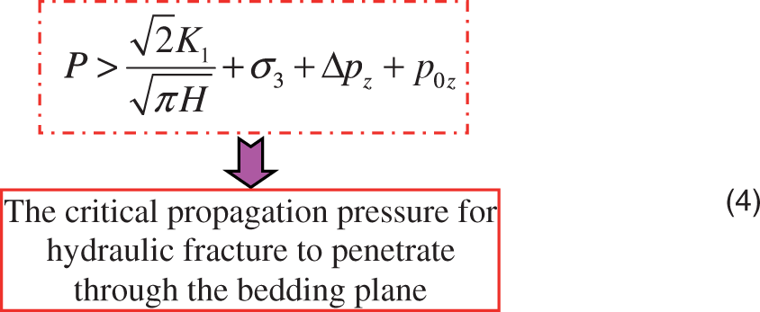
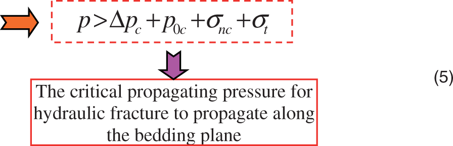
Criteria for hydraulic fracture penetrating the bedding plane
The condition that the hydraulic fracture penetrates the bedding plane is

The propagation of the main hydraulic fracture belongs to the Model I fracture type

Substituting equation (2) into equation (1) leads to

Equation (3) can also be written as
where 2. Criteria for hydraulic fracture propagating along the bedding plane
When the resultant force of the effective water pressure and the normal stress at the tip of the bedding plane fracture is larger than the tensile strength of the bedding plane, the hydraulic fracture propagates along the bedding plane (Figure 3(a))

where
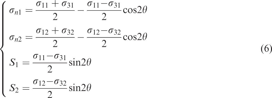
The stress state of the bedding plane can be written as (Figure 4)
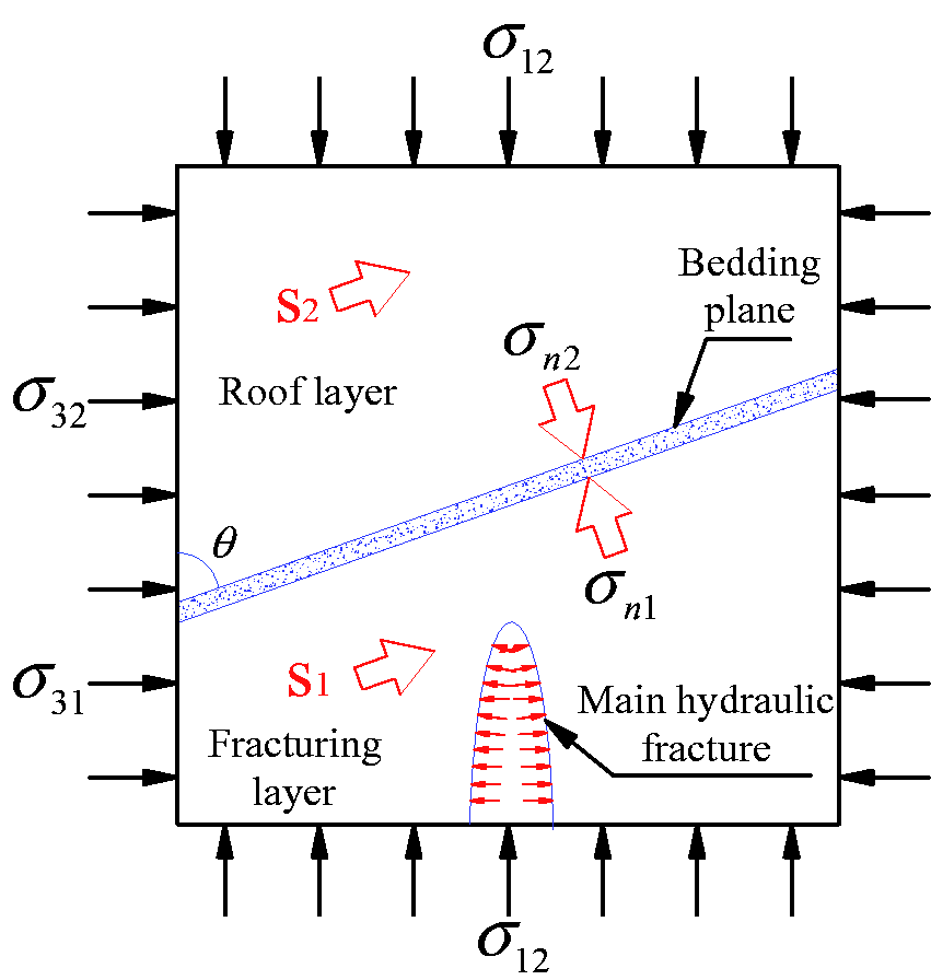
Stress state of the bedding plane during hydraulic fracturing.
In the direction perpendicular to the bedding plane, the forces reach a balance. Thus, the stress state of the area near the bedding plane can be written as
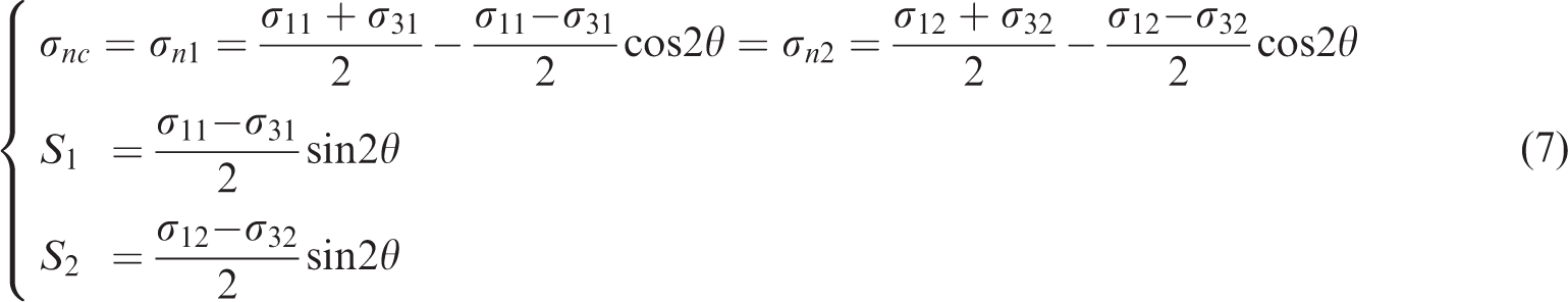
The propagation criteria for hydraulic fracture intersecting with the bedding plane can be written as follows.
When

The hydraulic fracture preferentially penetrates the bedding plane.
When

The hydraulic fracture preferentially propagates along the bedding plane
When

The hydraulic fracture both penetrate the bedding plane and propagate along the bedding plane at the same time.
Fully three-dimensional propagation model for hydraulic fractures
The height of the hydraulic fracture is not equal to the thickness of the fracturing layer. When hydraulic fractures propagate to a certain range, growing fractures exist in the roof and floor layer (Figure 1(b)). The main hydraulic fracture will propagate along the direction perpendicular to the minimum principal stress
Based on previous true triaxial physical simulation experiments of hydraulic fracturing, a fully three-dimensional propagation model for hydraulic fractures is developed (Figure 5). In this model, principles of elastic mechanics, fluid mechanics, and fracture mechanics are used and the vertical water flow, water leak-off, and interface effect are taken into consideration. Basic equations of this model include the continuity equation, equations of water pressure decline, equations of the length and aperture of the main hydraulic fracture and the bedding plane fracture, and equations of the height of the main hydraulic fracture and the width of the bedding plane fracture.
Schematic diagram of the fully propagation model for hydraulic fractures in rock strata containing bedding planes.
Assumptions in the model
The rock and the bedding plane are homogeneous and linear elastic. The calculation of the physical dimension of the hydraulic fracture is based on the linear elastic theory. The shape of the vertical cross section of the hydraulic fracture is ellipse. The water flow within the fracture is laminar flow. The impact of thermal field is not taken into consideration. The water injection rate is constant.
Equation of continuity
The total injected water consists of the water to generate the main hydraulic fracture and the bedding plane fracture and the infiltrated water in the main hydraulic fracture and the bedding plane fracture. According to the principle of mass conservation, the total injected water equals the sum of the water generating the main hydraulic fracture and the bedding plane fracture, i.e.
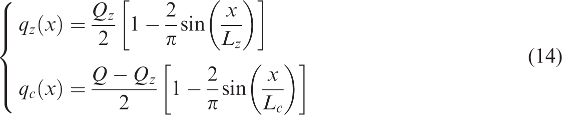
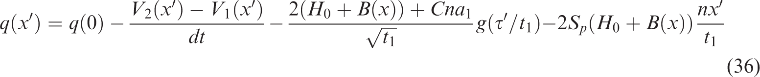
Along the length of the main hydraulic fracture and the bedding plane fracture, the increment of water flow,
On the basis of previous research, the distribution of the flow rate along the fracture length is
Pressure decline equations
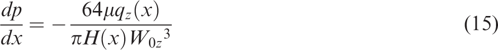
The pressure decline equation of water flow in the length direction of the main hydraulic fracture (Wang and Zhang, 1998) is
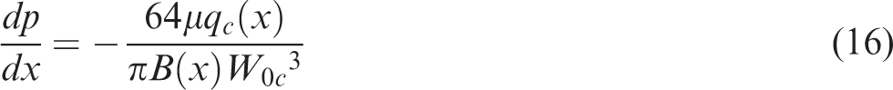
Similarly, the pressure decline equation of water flow in the length direction of the bedding plane fracture is
Therefore

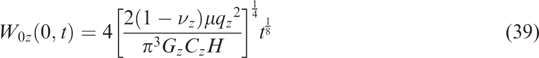
For vertical hydraulic fracture, the maximum aperture of the ellipse-shaped cross section (Figure 5) (Wang and Zhang, 1998) is

Meanwhile, the following equation holds
Substituting equation (19) into equation (18) and then substituting the result into equation (15), the water pressure decline equation can be written as (Wang and Zhang, 1998)
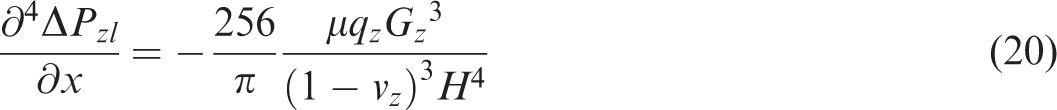
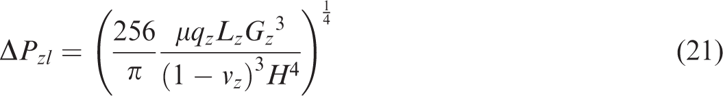
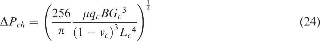
Calculate the integral of equation (20) from x=0 to x=L, then the pressure decline equation of the vertical hydraulic fracture in its length direction is
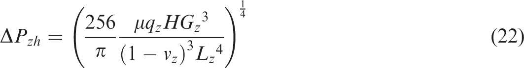
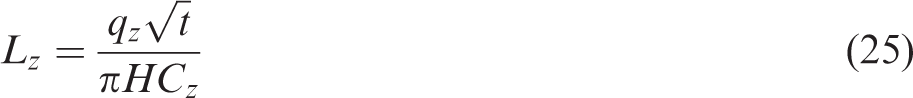
Similarly, the pressure decline equation of vertical hydraulic fracture in its height direction can be derived as
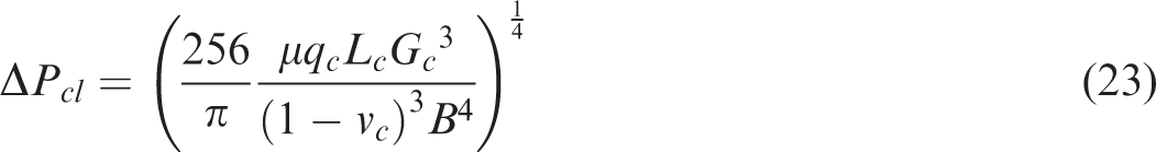
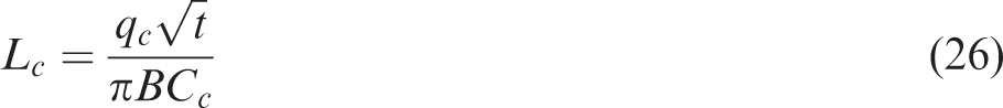
The pressure decline equation of the bedding plane fracture in its length direction is
The pressure decline equation of the bedding plane fracture in its width direction is
Equations of the length and aperture of the main hydraulic fracture and the bedding plane fracture
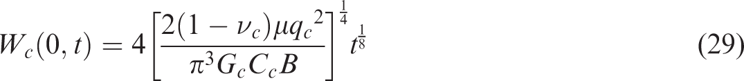
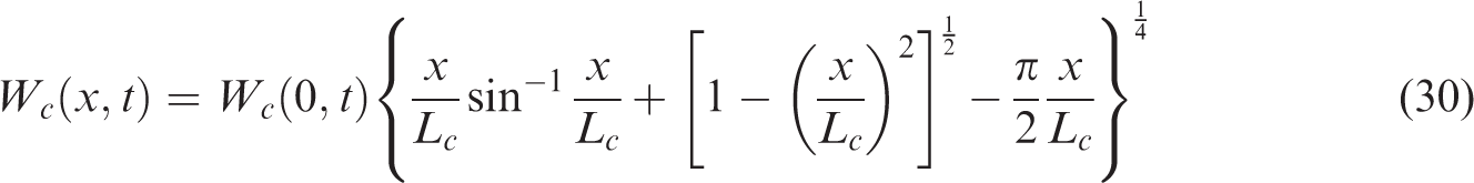
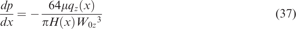
The aperture of the three-dimensional fracture is equivalent to the fracture aperture in the vertical cross section of the fracture (Figure 1(c)), which is calculated by two-dimensional methods. The fracture aperture
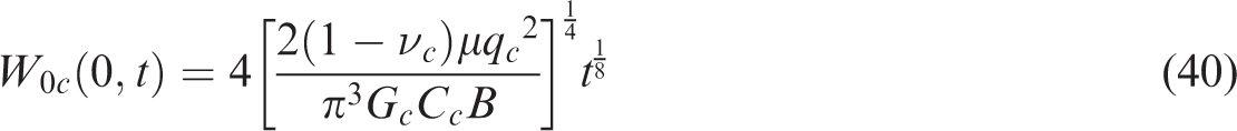
And the width of the bedding plane fracture,
The width of the main hydraulic fracture at its initiation location is
The equation of the width of the main hydraulic fracture at any point can be derived as

The equation of the width of the bedding plane fracture at the initiation location can be written as
The equation of the width at any point of the bedding plane fracture is
Equations of the height of the main hydraulic fracture and the width of the bedding plane fracture
According to the theory of fracture mechanics, the fracture propagates only when the stress intensity factor reaches the fracture toughness of the rock mass. Based on the calculation formula of stress intensity factor, the following equations can be obtained.
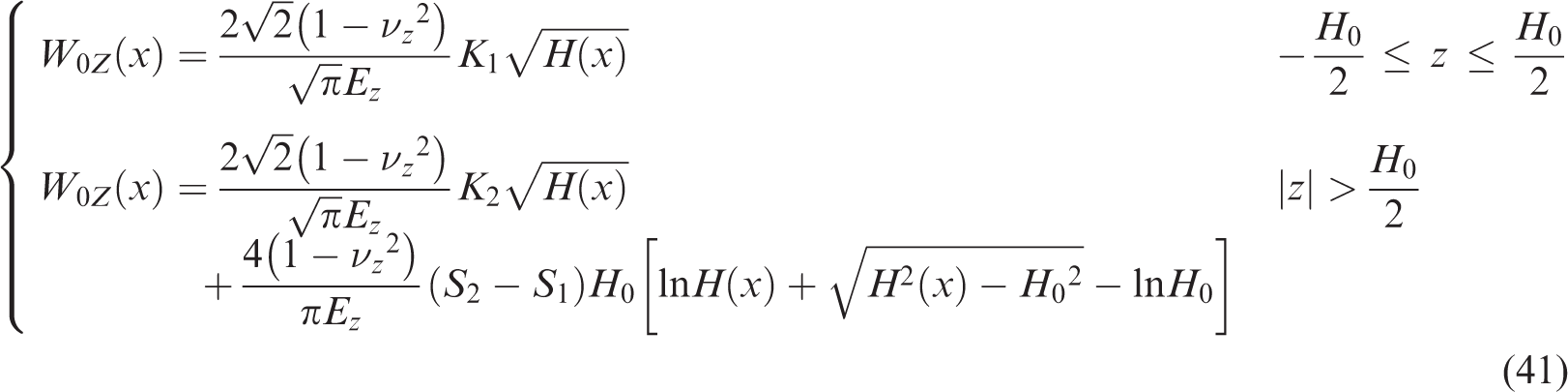
①. When hydraulic fractures propagate in the fracturing layer, i.e.

②. When hydraulic fractures extend beyond the fracturing layer, i.e.
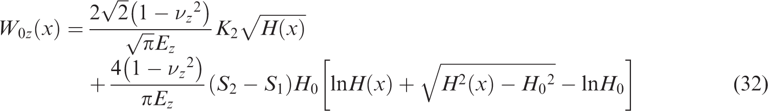
Namely

③. When hydraulic fractures propagate into the bedding plane, i.e.

Based on the above analysis, the fully three-dimensional propagation model for hydraulic fractures are as follows.
(1) Equations of continuity
The continuity equation of the main hydraulic fracture is

The continuity equation of the hydraulic fracture within the bedding plane
(2) Equations of pressure decline
The pressure decline equation of the main hydraulic fracture is
The pressure decline equation of the hydraulic fracture within the bedding plane

(3) Equations of fracture length
The equation of the length of the main hydraulic fracture
The equation of the length of the hydraulic fracture within the bedding plane
(4) Equations of the height of the main hydraulic fracture is as follows
(5) Equation of the width of the hydraulic fracture within the bedding plane

Verifications and analysis of the model
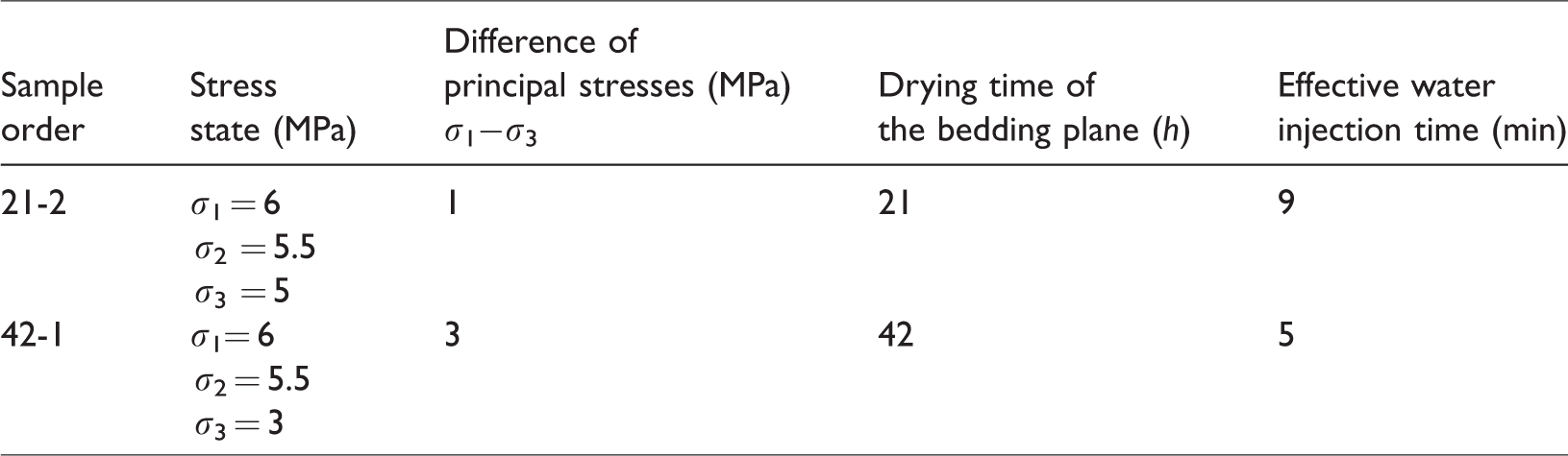
The fully three-dimensional propagation model is verified by physical experiments with true triaxial hydraulic fracturing experimental system (Huang, 2009; Huang et al., 2011). Samples with maximum size of 500 mm × 500 mm × 500 mm can be tested in this experimental system. Table 1 shows the experimental program of hydraulic fracturing experiments. The water injection rate is set as 500 ml/min.
Experimental program.
Cement mortar samples are used in this experiment to simulate rock. The main parameters in the experiments are as follows: the dynamic viscosity of water,
The length and height of the main hydraulic fracture
Substitute
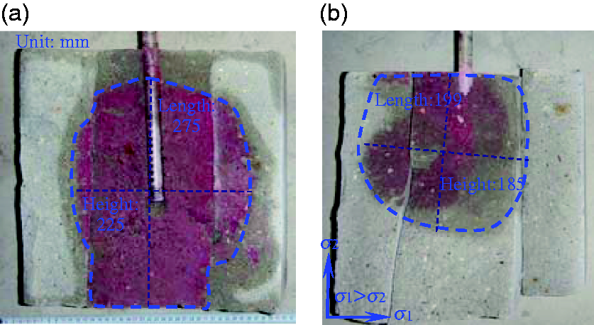
The geometry of the main hydraulic fracture (Huang and Liu, 2017). (a) Sample 21-2 and (b) sample 42-1.
The length and width of the bedding plane fracture
Substitute
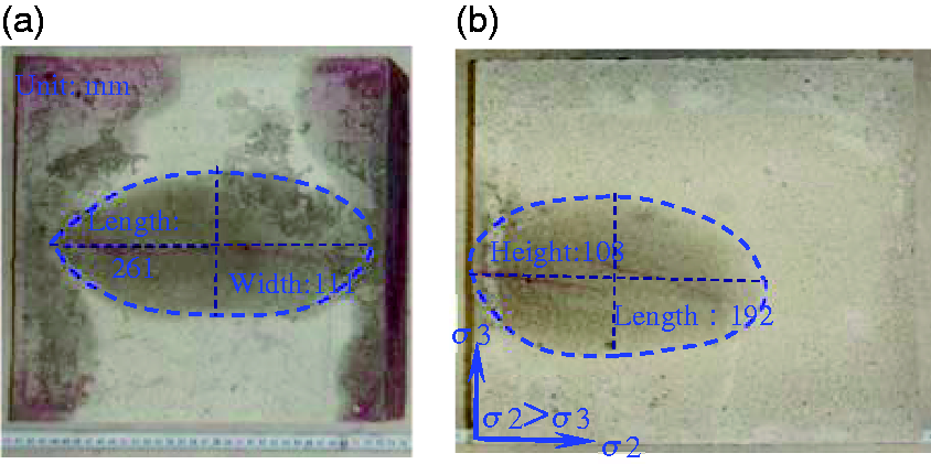
Geometry of the bedding plane fracture (Huang and Liu, 2017). (a) Sample 21-2 and (b) sample 42-1.
The aperture and the height of the main hydraulic fracture
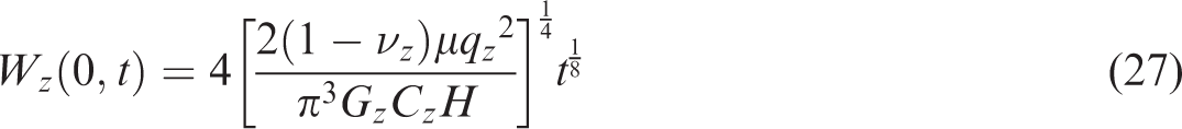
The aperture of the main hydraulic fracture is calculated to be 0.054 mm by substituting the fracture height of 225 mm (Figure 6(a)) and other parameters into equation (27). Then substitute the aperture of the main hydraulic fracturing into equation (32) and obtain the theoretical fracture height of 180 mm. Compared with the actual fracture height, the deviation of the calculated fracture height is 20%.
Substitute the fracture height of 185 mm (Figure 6(b)) and other parameters into equation (27) and the aperture of the main hydraulic fracture is calculated to be 0.053 mm. Then substitute the aperture into the equation of fracture height (equation (32)), the theoretical fracture height is calculated to be 180 mm, the deviation of which is 2.7%.
The aperture and fracture width of the bedding plane fracture
Substitute the fracture width of 111 mm (Figure 7(a)) and other parameters into equation (29), the aperture of the main hydraulic fracture is calculated to be 0.09 mm. Then substitute the calculated fracture aperture into the equation of fracture height (equation 34) and obtain the theoretical fracture width of 117 mm. There exists an error of 5.1% between the calculated value and the actual value of the fracture width.
Substitute the fracture width of 108 mm (Figure 7(b)) and other parameters into equation (29), the aperture of the main hydraulic fracture is calculated to be 0.084 mm. Then substitute the calculated fracture aperture into equation (34) and the theoretical fracture width is calculated as 102 mm, with a deviation of 5.6%.
The deviations of the above calculated results are all less than 20%, which meets the requirements of engineering applications. Therefore, the mechanical model can be used in engineering.
Conclusions
Based on previous physical experiments, a mechanical model for hydraulic fracturing in horizontal borehole is established. A fully three-dimensional model for hydraulic fracture propagation morphology is developed. On the basis of propagation behaviors of the main hydraulic fracture and the bedding plane fracture in physical experiments, the fracture failure mechanism of the main hydraulic fracture as well as the tensile failure mechanism of the bedding plane fracture is obtained, with the effect of pore pressure and the growth of microcracks taken into consideration. The mechanical conditions for the propagation of the main hydraulic and the bedding plane fracture are also derived. The criteria for hydraulic fractures penetrating through the bedding plane are given out. On the basis of previous true triaxial physical simulation experiments of hydraulic fracturing, employing theories of elastic mechanics, fluid mechanics, fracture mechanics, and others, a fully three-dimensional propagation model of hydraulic fractures is established. In this mechanical model, the vertical water flow, water leak-off, and the effect of bedding plane are taken into consideration. The following basic equations of the model are solved: the equation of continuity, the equation of water pressure decline, the equation of the height and aperture of the main hydraulic fracture and the bedding plane fracture, and the equation of the height of the main hydraulic fracture and the width of the bedding plane fracture. Hydraulic fracturing experiments in samples containing bedding planes are used to verify the basic equations of the length, aperture, width, and height of hydraulic fractures. All the deviations of the calculated values are less than 20%, which meet the requirements of the engineering application. The model has its limits so some assumptions should be included: The rock and the bedding plane are homogeneous and linear elastic; the calculation of the physical dimension of the hydraulic fracture is based on the linear elastic theory; the shape of the vertical cross section of the hydraulic fracture is ellipse; the water flow within the fracture is laminar flow; the impact of thermal field is not taken into consideration; the water injection rate is constant.
Footnotes
Declaration of conflicting interests
The author(s) declared no potential conflicts of interest with respect to the research, authorship, and/or publication of this article.
Funding
The author(s) disclosed receipt of the following financial support for the research, authorship, and/or publication of this article: Financial support for this work, provided by the National Science Fund for Excellent Young Scholars (No. 51522406) and the Fundamental Research Funds for the Central Universities (China University of Mining and Technology) (No. 2015XKZD04), is gratefully acknowledged.