
Abstract
Coal mining results in strata movement and surrounding rock failure. Eventually, manual mining space will be occupied by the destructed coal rock, making it difficult to conduct field tests of the coal seam to explore gas seepage and transport patterns. Therefore, computational fluid dynamics (CFD) numerical computation is an important tool for such studies. From the aspect of gas pre-drainage, for layer-through boreholes in the floor roadway of the 8,406 working face in Yangquan Mine 5 in China, reasonable layout parameters were obtained by CFD optimization. For effectively controlling the scope of boreholes along coal seam 9 in the Kaiyuan Mine, CFD computation was performed. The results revealed that the horizontal spacing between boreholes should be ≤2 m when a tri-quincuncial borehole layout is used. Optimization of the surface well position layout for the fault structure zone in the Xinjing Mine of the Yangquan mining area indicated that the horizontal distance between the surface well and the fault plane should be <150 m. From the aspect of gas drainage with mining-induced pressure relief, CFD computation was performed for pressure-relieved gas transport in the K8205 working face of Yangquan Mine 3. The results showed that forced roof caving should be used before the overhang length of hard roof reaches 25 m in the K8205 working face to avoid gas overrun. From the aspect of gas drainage from the abandoned gob, surface well control scopes at different surface well positions were computed, and an O-ring fissure zone is proposed as a reasonable scope for the surface well layout. CFD computation has been widely applied to coal and gas co-extraction in the Yangquan mining area and has played a significant role in guiding related gas drainage engineering practice.
Introduction
Coal is a pore-fracture porous medium, and the gas seepage law in coal has been studied by scholars worldwide, resulting in coal seam gas seepage–diffusion theory. This theory has been systematically elaborated in coalbed–methane occurrence and flow theory (Zhou and Lin, 1999). Nie et al. (2001) established a mathematical gas seepage–diffusion model and performed numerical computation. Sun (1987, 1993) considered gas flow in coal as a seepage–diffusion composite movement of a compressible fluid in a nonhomogeneous medium, established a mathematical solid–gas coupling model for gas seepage in coal seams, and computed it using CFD software. Saghafi and Willams (1988) coupled diffusion and seepage equations by mathematical derivation according to Fick's law and Darcy's law and proposed a dynamic model for gas seepage–diffusion. Valliappan and Zhang (1996) proposed a mathematical model in which the effect of diffusion of adsorbed methane gas from the solid matrix to the voids was taken into account. Li et al. (2017) established a mathematical model of gas flow in different types of wells on the basis of seepage theory. To study the coupled process of the actual mining-induced anisotropic mechanical behaviors and the gas seepage phenomena in coal, Zhang et al. (2017) built an anisotropic coal permeability model that considers the complex stress evolution process, microfracture propagation, and gas sorption–desorption effects.
Compared with the gob, fractures arising from coal mining are smaller, thus the gob is deemed as a porous medium by scholars and the variability of gas transport within the gob has been studied. Ding (1996) gave a nonlinear seepage equation for multicomponent gas in the gob, theoretically supporting the use of CFD software in solving for the gob seepage field. Li et al. (2004, 2005, 2008) made great efforts in theoretical research on CFD computation of gas in the gob, with fruitful achievements in the mathematical modeling of gas transport in the gob and finite element computation.
Based on previous studies, we have conducted numerous theoretical and experimental studies on variabilities of gas flow in coal and gas transport in the gob, derived a dynamic permeability equation for low-permeability coal and a spatial distribution equation for permeability in porous gob media, established a more realistic solid–gas coupling model, and obtained visualized CFD computation results (Qin et al., 2015, 2018). In related studies with high gas, low permeability, and complicated geology in the Yangquan mining area in China as an engineering background, gas pre-drainage technology, gas drainage technology with mining-induced pressure relief, and gas drainage technology for abandoned gobs have been optimized, offering powerful technical support to coal and gas co-extraction in the Yangquan mining area.
Permeability of porous media in CFD computation
Permeability of porous media is an important parameter in fluid flow models and is decisive to the accuracy of CFD computation. Relevant studies indicate that coal stress has a significant impact on permeability (Danesh et al., 2017; Swan, 1983; Durucan and Edwards, 1986; Gilman and Beckie, 2000). Therefore, we designed a seepage test scheme based on the stress evolution pathway of the coal ahead of the working face and obtained solid–gas coupling equations for coal stress versus coal permeability. In addition, by employing three-dimensional physical simulation of the mining-disturbed overburden, we derived a spatial distribution equation for the permeability of porous media in the gob.
Solid–gas coupling equations for coal stress versus coal permeability
Advanced abutment pressure tests on working faces in the Yangquan mining area revealed that the maximum advanced abutment pressures were 15–18 MPa and horizontal stresses were 5–6 MPa (Qin and Xu, 2020). Based on the evolutionary characteristics of the advanced abutment pressure, an experimental scheme was designed in which horizontal and vertical stresses were applied, as shown in Figure 1.
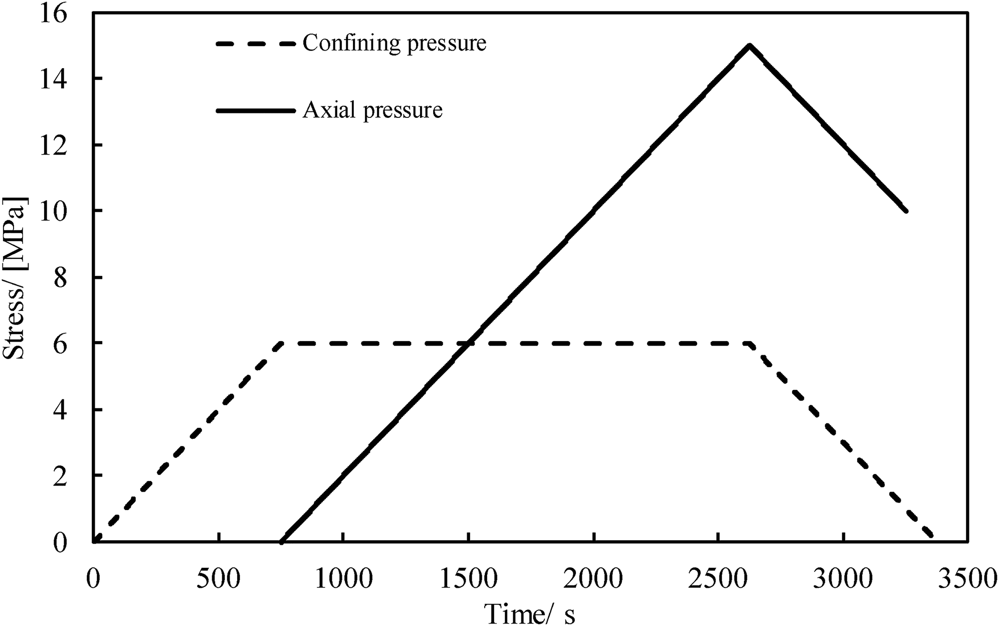
Loading and unloading schemes of horizontal and vertical stresses during the seepage test.
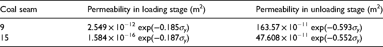
According to the experimental scheme shown in Figure 1, a seepage test on coal samples from Yangquan mining area was performed. During the test, the gas pressure at the gas inlet was 0.9 MPa, and solid–gas coupling equations for vertical stress (σy) versus coal permeability (P) during loading and unloading were obtained by data fitting, as given in Table 1.
Fitting relationships between permeability and volumetric strain of the coal samples.
Spatial distribution equation for permeability of porous gob media
Based on the field situation of the 8,205 working face of Yangquan Mine 3, we designed an experimental scheme using a three-dimensional gob gas drainage simulation test system to monitor the vertical displacement of the strata overlying this working face and obtained the following spatial distribution functions for vertical displacement W (in meters) by data fitting (Qin et al., 2015):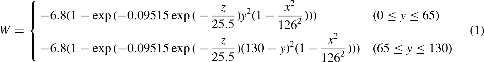


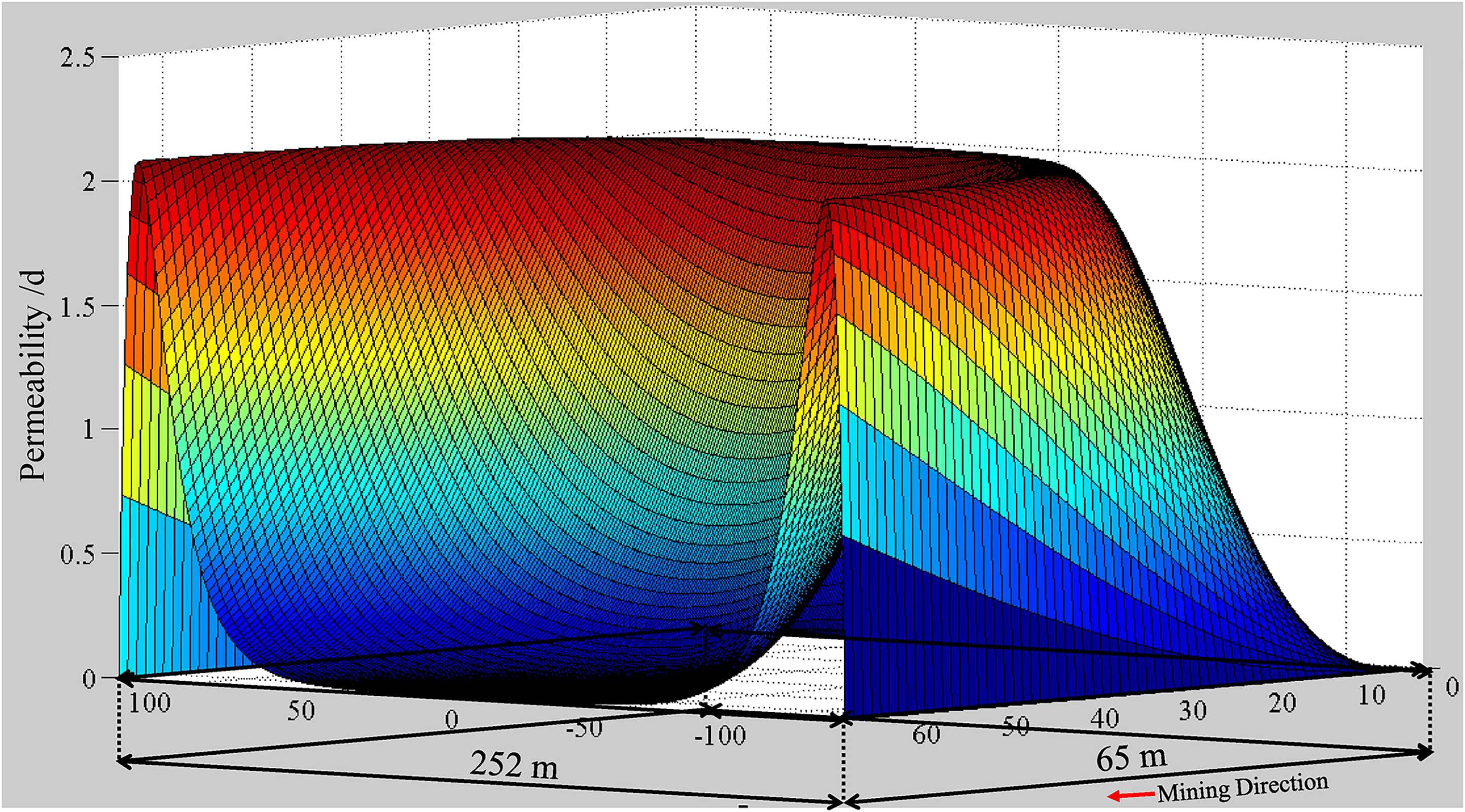
Spatial distribution of permeability along the z = 20 profile.
CFD optimization of gas pre-drainage from the coal seam
CFD optimization of layout parameters of layer-through boreholes in the floor roadway
In Yangquan Mine 5, the 8,406 working face has elevations of 380–450 m, ground elevations of 865–957 m, and depths of 485–510 m. Its strike length is 935 m, and its dip length is 195 m. Based on geological data, coal seam 15 has a total thickness of 6.25 m and dip angles of 4°–10°. At the 8,406 working face, two floor roadways were laid 6 m underneath coal seam 15. To eliminate outburst hazard in the intake airway and return airway of the 8,406 working face in Yangquan Mine 5, layer-through boreholes were constructed in the floor roadway to pre-drain gas from coal seam 15.
Based on the field conditions of Yangquan Mine 5, a numerical model was established by using COMSOL to investigate the pre-drainage effect of layer-through boreholes and optimize drainage parameters. During gas drainage from low-permeability coal seams, borehole spacing and drainage time have considerable impact. Therefore, numerical computation schemes for these two important factors were designed in this study. In the numerical computation, borehole diameter and drainage pressure were set to 110 mm and 10 kPa, respectively, while the experimental measurement of coal seam 15 (Table 1) was used as the coal permeability. The average mining depth of 15,101 working face is 497.5 m. If calculated according to 2.5 MPa per 100 m strata, the vertical stress is 12.44 MPa. Assume that the lateral pressure coefficient is 1, the horizontal pressure was converted into a uniform load of 12.44 MPa, and applied to the lateral boundary of the model. The drainage time was set to 180 days, while borehole spacings were set to 1, 2, 3, and 4 m, respectively. The gas pressure of the coal seam must be <0.74 MPa in China. As can be seen from the gas pressure distribution around a borehole under different borehole spacings (Figure 3(a)), the gas pressure at the model center increased constantly with increasing borehole spacing; when borehole spacing was 3 m, the gas pressure at the model center exceeded 0.74 MPa and an unqualified area was present at the model center. For layer-through boreholes in Yangquan Mine 5, the horizontal spacing was 3 m, the vertical spacing was 6 m, and the outburst control effect at the model center was not qualified 180 days after drainage based on the results of computation according to different borehole spacing schemes. Therefore, the drainage time of the layer-through boreholes has to be increased. In Yangquan Mine 5, layer-through boreholes were laid according to actual positions, and drainage times were set to 180, 240, 300, and 360 days, respectively. Based on the calculation results in Figure 3(b), when the drainage time exceeded 300 days, the gas pressure at the model center was <0.74 MPa, thus the outburst control effect was qualified. Therefore, if coal seam 15 is expected to be qualified within 180 days, then the borehole spacing has to be decreased to 2.5 m; to keep the current borehole layout scheme unchanged, the drainage time has to be extended to 300 days.
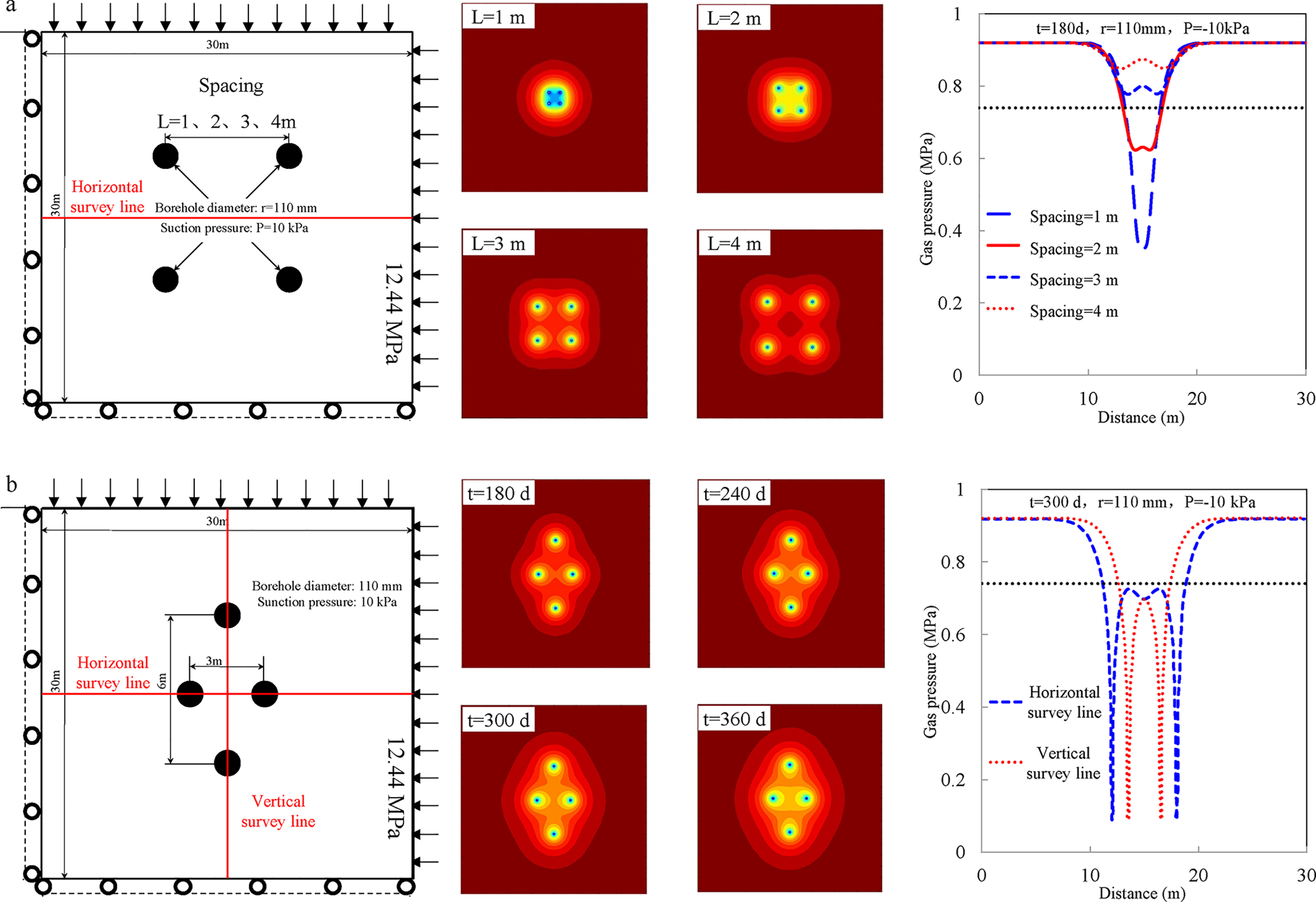
Gas pressure distribution around a borehole under (a) different borehole spacings and (b) different drainage times.
CFD optimization of layout parameters of boreholes along the coal seam
The ground elevation at the 9,712 working face in the Kaiyuan coal mine is 1,099–1,125 m, and the elevation of the working face is 742–758 m. The working face has a strike length of 1,360 m and a dip length of 220 m. The coal seam has a thickness of 5.17 m and a dip angle range of 1°–7°. For this working face, U + L ventilation was used, and boreholes along the coal seam were used for gas drainage from the coal seam being worked. The boreholes had a spacing of 2 m and lengths of 120 m, diameters of 120 mm, and their distance from the coal seam floor was 1 m.
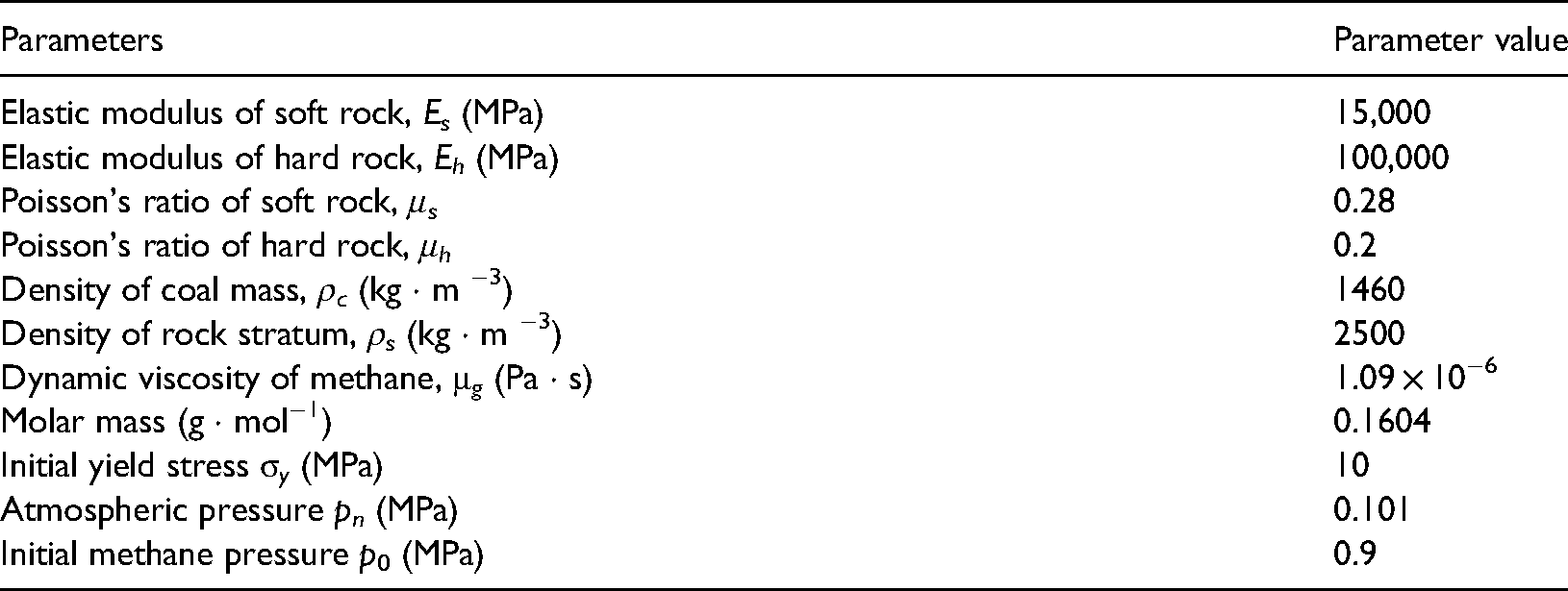
In designing the boreholes along the coal seam, their effective control scope was disregarded, hence the borehole layout has no scientific merit. Based on field conditions of coal seam 9 in the Kaiyuan Mine, a numerical computational model was established by using COMSOL. For the numerical computation, the borehole diameter d was set to 110 mm, the drainage pressure was 10 kPa, the original gas pressure of coal seam 9 was 0.448 MPa, the borehole-to-floor distance was 1 m, and the drainage time was 180 days. The experimental measurement of coal seam 9 (Table 1) was used as the permeability of the coal around the boreholes. The model parameters are listed in Table 2.
Model parameter values.
Borehole spacing is an important parameter in the borehole layout along the coal seam. Too wide a borehole layout spacing would result in a blind area of drainage between boreholes while too tight a borehole layout spacing would increase construction cost of the whole drainage system; therefore, a reasonable borehole spacing is crucial to gas control in the Kaiyuan coal mine. We designed a computing scheme for this important parameter, setting borehole spacings to 1, 2, 3, and 4 m, respectively. In the context of borehole drainage, a reduction in gas pressure by 50% serves as a criterion for evaluating the effective control scope of a borehole. Given variable borehole spacings, effective control scopes of boreholes along coal seam 9 are shown in Figure 4. The figure demonstrates that blind areas of drainage will be present in the context of a one-row borehole layout as coal seam 9 is too thick.
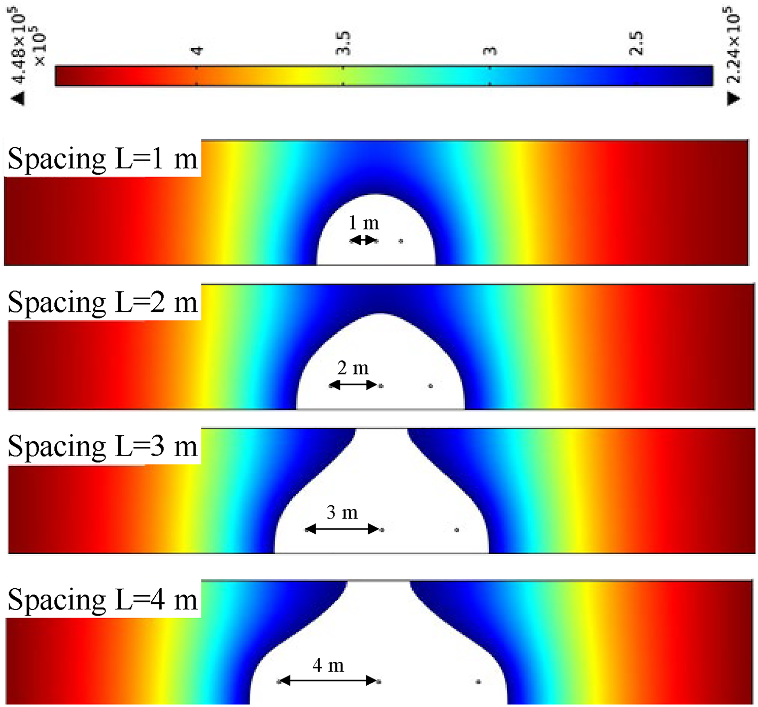
Effective control scopes of boreholes along coal seam 9 in the context of a one-row borehole layout.
To address the issue of blind areas of drainage in a one-row borehole layout in coal seam 9 of the Kaiyuan Mine, we arranged the boreholes along the coal seam in a tri-quincuncial pattern. Effective control scopes of boreholes along coal seam 9 in a tri-quincuncial pattern are shown in Figure 5. The computation results reveal that there are no blind areas of drainage between drainage boreholes when the horizontal borehole-to-borehole distance was 2 m (Figure 5(a)); when the horizontal borehole-to-borehole distance was 3 m, however the borehole height was adjusted, blind areas would appear in the drainage zone (Figure 5(b)). Therefore, the horizontal distance between boreholes should be ≤2 m when boreholes along coal seam 9 in the Kaiyuan Mine are arranged in a tri-quincuncial pattern.
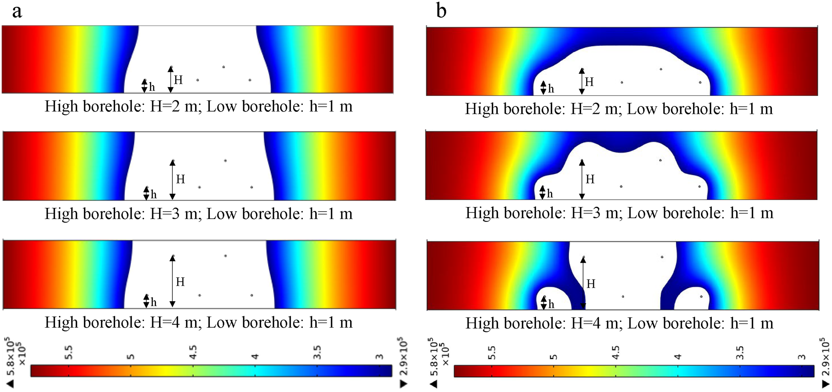
Effective control scopes of boreholes along coal seam 9 arranged in a tri-quincuncial pattern when the horizontal distance between boreholes is (a) 2 m and (b) 3 m.
CFD optimization of parameters of a surface well in the fault structure zone
Coal and gas outbursts are unevenly distributed in a coal seam, and real outburst area accounts for only 10%–20% of the whole coal seam area. Such an unbalanced distribution of coal and gas outbursts is related to geological factors, and geological structure is one dominant factor controlling the distribution of coal and gas outbursts. In the Xinjing Mine, surface well XJ-1 was drilled at a reverse fault footwall and hydraulically fractured such that the fracturing-derived high-permeability zone became connected to the gas-enriched high-permeability zone near the fault to improve the effect of gas drainage via surface wells. Surface well XJ-1 has a depth of 532.11 m, and its drilled horizon is the Middle Carbonaceous Taiyuan Formation. Surface well XJ-1 is of two-stage wellbore structure, of which the first stage is 21.83 m long with a wellbore diameter of 311 mm and the second stage is 510.28 m long with a wellbore diameter of 215.9 mm.
A numerical computational model (Figure 6) was established based on logging data from surface wells in the Xinjing Mine. The model was centrally symmetric with respect to the fault plane and 87.6 m high and 300 m wide, the coal seam was 2.6 m thick, the fault throw was 15 m, and the fault dip angle was 60°. The upper rock layer with a thickness of 417 m in the model was converted into a uniform load of 10.44 MPa applied to the top interface of the model. The model parameters are listed in Table 2.
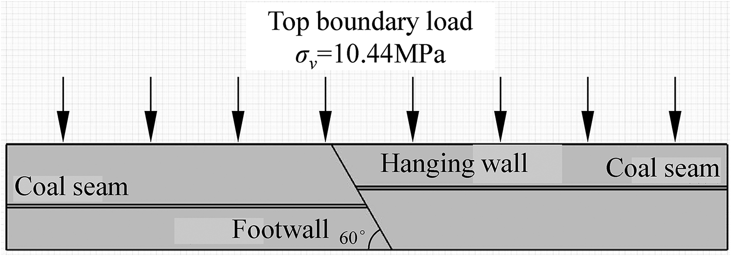
Geometric model and its boundary conditions.
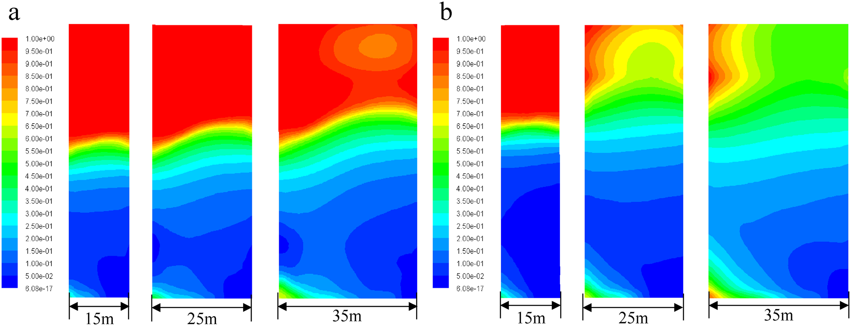
The surface wells had a fracturing radius of 130 m and a fracture width of 5 mm. The experimental measurement of coal seam 15 (Table 1) was used as the coal permeability. Distances between the surface wells and the fault plane at the footwall of the coal seam were set to 250, 200, and 150 m, respectively. As illustrated by the computation results shown in Figure 7, the vertical stress on the coal mass varied with a trend opposite to that of permeability, and, within the fracture scope, the pressure-relief zone had a higher permeability while the vertical stress concentration zone outside the fracture had a lower permeability; when a surface well was 200 m away from the fault plane, the fracturing-derived high-permeability zone was not connected to the gas-enriched high-permeability zone near the fault (Figure 7(a) and (b)); when a surface well was 150 m away from the fault plane, the two zones were connected to each other (Figure 7(c)). Therefore, the horizontal distance between a surface well and the fault plane should be <150 m to guarantee the effect of gas drainage. Based on the above CFD computation results, the layout of the XJ-1 surface well in the Xinjing Mine was optimized. Field test results revealed that the XJ-1 surface well delivered 276,000 m3 of gas in nine months and that the maximum daily gas output was 4,707 m3/day.
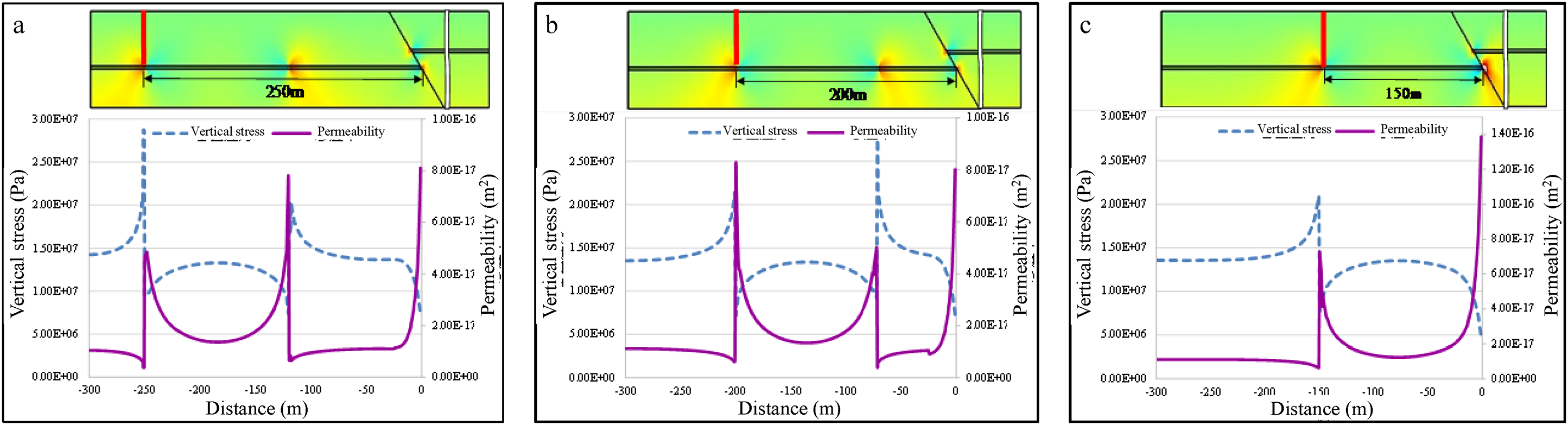
Contour plots of vertical stress and curves of permeability when the spacings between the surface well and the fault plane are (a) 250 m, (b) 200 m, and (c) 150 m.
CFD numerical computation of gas drainage with mining-induced pressure relief
Optimization design of gas drainage via layer-through boreholes
The 15,101 working face in the Xindadi Mine with a depth of 344–337 m exploits coal seam 15 in the Yangquan mining area. Its strike length is 500 m, its inclination length is 120 m, the coal seam is 4.50–5.30 m thick with a mean thickness of 4.90 m, and dip angles of the coal seam are 8°–12°. Its overlying adjacent coal seams are the unmined coal seams 10, 11, 12, 13, and 14, and thicknesses of these coal seams are 0.15, 0.50, 0.54, 0.26, and 0.45 m, respectively, with distances of 56.92, 49.75, 47.21, 35.54, and 13.96 m from coal seam 15, respectively. At the 15,101 working face, U + L ventilation was used, there were 6-m-long protective coal pillars between the gas tail gateway and the return airway, and one crossheading was set every 15 m between the roadways.
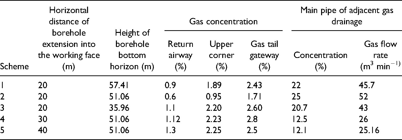
During mining of the 15,101 working face, gas drainage in the gob was performed via layer-through boreholes in adjacent seams. However, the layout parameters of these boreholes were empirically determined without a theoretical scientific rationale. Therefore, based on the field situation of the 15,101 working face, a numerical computational model was established to set computing schemes for the borehole bottom horizon height and horizontal distance of the borehole extension into the working face, respectively, and the spatial distribution function of gob permeability was determined from equation (3). First, the horizontal distance of the borehole extension into the working face was fixed to 20 m (Figure 8), and heights of the borehole bottom horizons were 57.41 m (scheme 1), 51.06 m (scheme 2), and 35.96 m (scheme 3) from the floor of coal seam 15, respectively. The gas drainage effects under different schemes are listed in Table 3. Gas concentration at the upper corner of the 15,101 working face under schemes 1 and 3 exceeded the warning value (0.1%). It can be seen from Table 3 that the gas drainage concentration and gas drainage volume are both maximum under scheme 2. Hence, to obtain the best gas drainage effect, a reasonable bottom horizon of boreholes in the 15,101 working face was set to 51.06 m. Second, the bottom horizon height of boreholes was fixed to 51.06 m, and the horizontal distances of borehole extensions into the working face were 20 m (scheme 2), 30 m (scheme 4), and 40 m (scheme 5), respectively. It can be seen from Table 3 that the gas concentration at the upper corner of the 15,101 working face under schemes 4 and 5 also exceeded the warning value. Therefore, a reasonable horizontal distance of layer-through borehole extension into the 15,101 working face in the Xindadi Mine was 20 m.
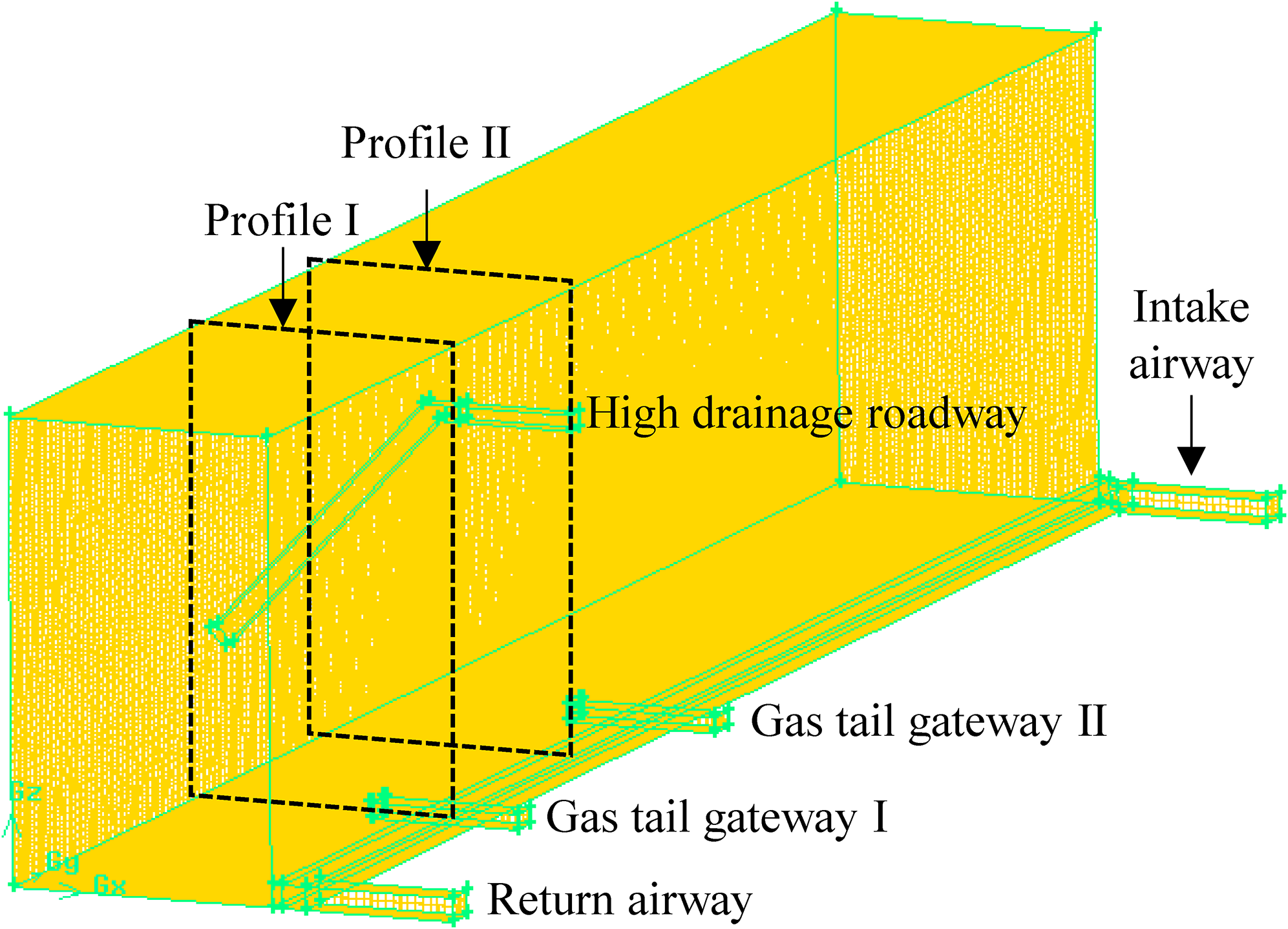
Model structures.
Gas drainage effect of layer-through borehole under different schemes.
Pressure-relieved gas transport during the preliminary mining period
In Yangquan Mine 3, the first weighting step of the K8205 working face reached only 35 m because of the hard roof. High-drainage roadways were used to extract gas from adjacent seams during the preliminary mining period, but prolonged overhanging of the hard roof rendered mining fractures unable to communicate with the gob in time, and upper corner of the working face was under serious threat of gas overrun during the preliminary mining period. To shorten the first weighting step of the working face, forced roof caving was going to be conducted by blasting so that mining fractures would develop prematurely to reach the high-drainage roadway and exert the gas drainage effect of high drainage in advance to solve the gas overrun problem of the K8205 working face during the preliminary mining period. To obtain reasonable parameters of forced roof caving, a numerical computational model was established based on the roadway layout and roof lithology of the K8205 working face (Figure 8).
Because the first key strata of the working face were 20 m away from the roof of the coal seam, the height of the fracture zone in the established model was set to 20 m when mining fractures do not communicate with the high-drainage roadways. Computing schemes were set up for different first weighting steps, namely, 15, 25, and 30 m. Contour plots of gob gas concentrations under different schemes are shown in Figure 9. Figure 9(a) shows the distribution of gas concentrations in the vertical profile of gas tail gateway II. Gas concentration in the gas-conductive fracture zone was lower as a result of dilution by the air leaked in the gob, whereas gas concentration in the lower part of the gob near the open–off cut was higher. As the length of the hard roof overhang and release of pressure-relieved gas increased, it became more difficult for the fresh air flow to dilute fully the high-concentration gas released from the gob, so gas concentration near the working face increased gradually. Figure 9(b) shows the distribution of gas concentrations in the vertical profile of gas tail gateway I. The aggregation effect of the gob gas was significant on the return air side, with gob gas flowing toward the working face becoming more serious than gas flow in the profile of gas tail gateway II, and out-of-limit gas concentration occurred near the working face when the hard roof overhang was 35 m long. The above results indicate that, before the length of the hard roof overhang in the K8205 working face reaches 25 m, forced roof caving has to be conducted; otherwise, there will be a potential risk of out-of-limit gas concentration at the top corner of the working face. Therefore, after roof pre-fracturing, the initial caving step of the hard roof decreases when a smaller area of gas pressure relief and a smaller volume of pressure-relieved gas are available in the adjacent coal seam, while gas-conductive fractures become connected to high-drainage roadways in advance, resulting in gas pre-drainage and enabling effective control of pressure-relieved gas emission toward the working face in the adjacent seam at the time of the initial pressure arrival from the hard roof.
Distribution of gob gas concentrations in different schemes. Vertical profiles of gas tails for (a) gateway II and (b) gateway I.
CFD numerical computation of gas drainage from the abandoned gob
In countries other than China, research efforts on abandoned gob gas drainage are under rapid development. In the late 1970s, four long horizontal boreholes were drilled into the Pittsburgh coal in Pennsylvania, and the cumulative methane production was 7.2 × 10⁶ m3 (Karacan et al., 2011). In 2001, Six AGM exploitation schemes producing an equivalent of 42.5 MWe are operational in the UK (Creedy et al., 2001). In Germany, the first power generation utilization plants from mine gas in the abandoned area of the Ruhr district were put into operation in 1997 in Herne, and Hangard, Kohlwald, and Sinnerthal produce 51 × 106 m3 of abandoned gob gas annually (Burrell and Kershaw, 2000; Kunz, 2004).
In Yangquan Mine 3, Coal seam 15 was exploited along the K8206 working face. The average inclination, thickness, and depth of this coal seam are 5°, 6.8 m, and 420–540 m, respectively. The incline width of the K8206 working face is 252.2 m, and the strike advancing length is 1,579 m. Its overlying adjacent coal seams were the unmined coal seams 3, 8, 11, 12, and 13. After closure of the K8206 working face, gas is still continuously released and accumulates inside the abandoned gob. Capturing this abandoned gob gas would not only provide a great amount of clean energy but also effectively reduce the greenhouse effect by gas dissipation into the air. Surface well drainage is an important way of exploiting and utilizing gas resources in abandoned gobs, and selecting surface well positions becomes a pivotal technical issue in exploitation and utilization of abandoned gob gas resources.
Based on the field conditions of the K8206 working face in Yangquan Mine 3, a FLUENT numerical model was established, and the spatial distribution function of gob permeability was determined from equation (3). The control scopes of surface wells as a function of position were computed, and the results are shown in Figure 10. In scheme 1, the surface well is located 10 m outside of the mining boundary, while in schemes 2, 3, 4, and 5, the surface well extends into the gob by 30 m in turn. Figure 10 shows that, in scheme 1, the surface well is located within the lateral fracture zone, and its control scope is the left half part of the O-ring fissure zone, spatially shown as a C shape. In scheme 2, the surface well is within the O-ring fissure zone and its control scope covers almost the whole O-ring fracture zone. In schemes 3, 4, and 5, as the surface well extends continuously into the compaction zone in the middle of the gob, its control scope shrinks constantly. Therefore, the O-ring fissure zone near the mining boundary is the most reasonable area for the location of the surface well.
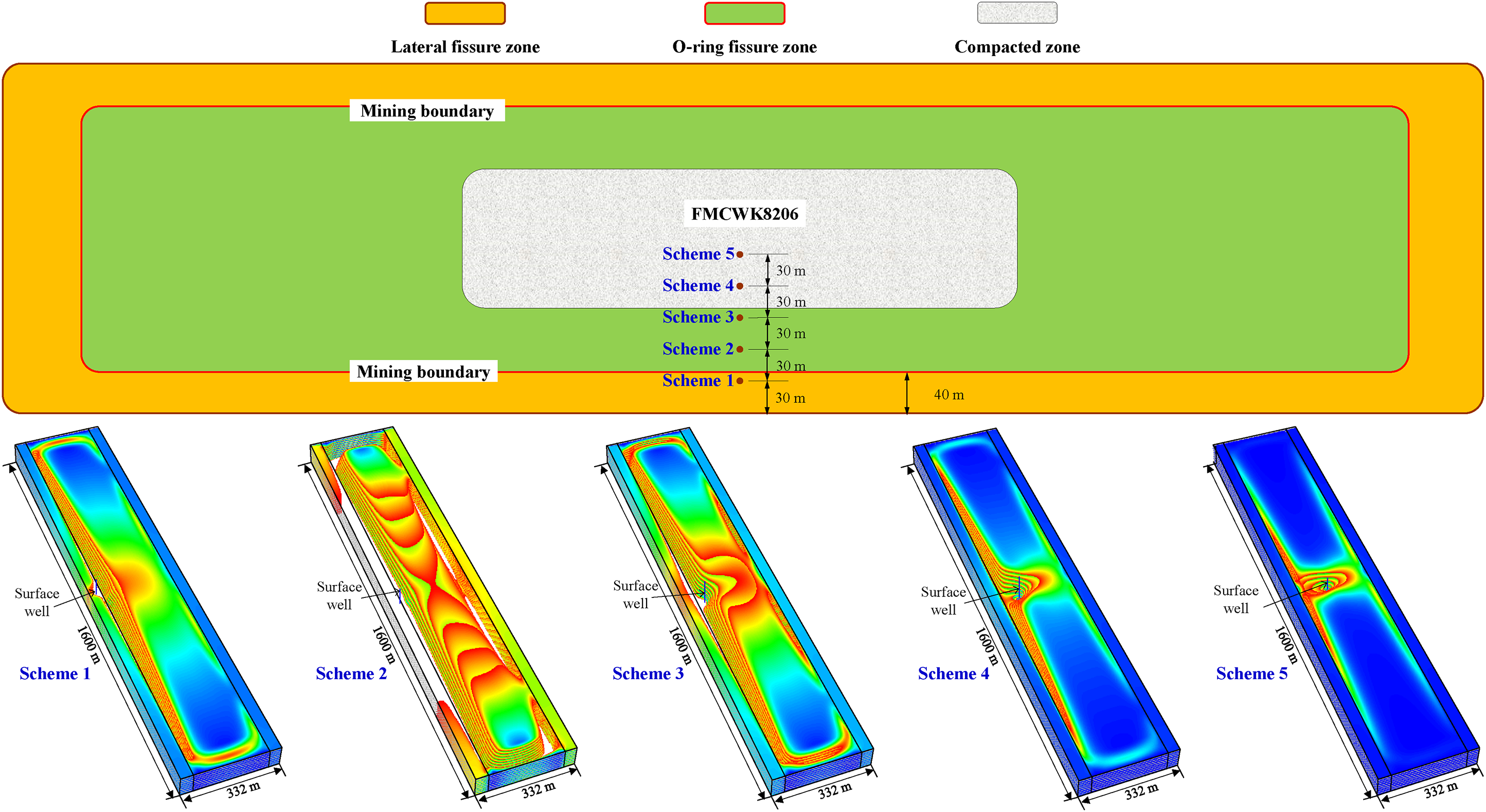
Control scopes of surface wells versus position.
In Yangquan Coal Mine No. 3, the first abandoned gob gas well (well #1) ran simultaneously through the O-ring fissure zones in the gobs of coal seams #12 and #15. After vertical well #1 had been completed, the engineering experiment on abandoned gob gas drainage through the vertical well was conducted. A trial run of 226 h was made, with the suction pump on the ground, and cumulative production reached 33,000 m3 in total.
Conclusions
For gas pre-drainage from the coal seam, layout parameters of layer-through boreholes in the floor roadway of the 8406 working face in Yangquan Mine 5 were optimized. The layer-through borehole spacing should be <2.5 m if gas drainage from this working face has to be qualified in 180 days, and drainage time should be extended to 300 days if the existing borehole layout remains unchanged. For effective control scopes of boreholes along coal seam 9 in the Kaiyuan Mine, CFD computation was performed. Because coal seam 9 is too thick, there will be blind areas of drainage when boreholes are arranged at one row, and horizontal spacing between boreholes should be ≤2 m when boreholes are arranged in a tri-quincuncial pattern. In the fault structure zone in the Xinjing Mine, the selection of surface well position was optimized, and the horizontal distance between surface well XJ-1 and the fault plane should be <150 m to ensure mutual connection between fracturing-derived high-permeability zones and gas-enriched high-permeability zones near the fault.
For gas drainage with mining-induced pressure relief, the layout parameters of layer-through boreholes in adjacent seams of coal seam 15 in the Xindadi Mine were optimized. As a result, a reasonable borehole bottom horizon was determined to be 51.06 m while a reasonable horizontal distance of the borehole extension into the working face was 20 m. For pressure-relieved gas transport at the K8205 working face of the Yangquan Mine 3 during the preliminary mining period, CFD computations indicated that forced roof caving of the K8205 working face has to be conducted before the overhang length of the hard roof reaches 25 m. Otherwise, there will be a potential risk that gas concentration at the upper corner of the working face would be out of limit.
For gas drainage from the abandoned gob, control scopes of surface wells varying in position were computed. The computation results reveal that a surface well within the O-ring fissure zone near the mining boundary had the largest control scope and that the O-ring fissure zone near the mining boundary is the most reasonable area for the location of the surface well.
Footnotes
Declaration of conflicting interests
The authors declared no potential conflicts of interest with respect to the research, authorship, and/or publication of this article.
Funding
This work was supported by the Independent research project of State Key Laboratory of Coal Resources and Safe Mining (No. SKLCRSM19X009), Fundamental Research Funds for the Central Universities (No. 2020ZDPYMS17), and Natural Science Foundation of China [No. 52174212].