
Abstract
Multistaged temporary plugging fracturing in horizontal wells is an emerging technology to promote uniform fracture propagation in tight reservoirs by injecting ball sealers to plug higher-flux perforations. The seating mechanism and transportation of ball sealers remain poorly understood. In this paper, the sensitivities of the ball sealer density, casing injection rate and perforation angle to the seating behaviors are studied. In a vertical wellbore section, a ball sealer accelerates very fast at the beginning of the dropping and reaches a stable state within a few seconds. The terminal velocity of a non-buoyant ball is greater than the fluid velocity, while the terminal velocity of a buoyant ball is less than the fluid velocity. In the horizontal wellbore section, the terminal velocity of a non-buoyant or buoyant ball is less than the fracturing fluid flowing velocity. The ball sealer density is a more critical parameter than the casing injection rate when a ball sealer diverts to a perforation hole. The casing injection rate is a more critical parameter than the ball sealer density when a ball sealer seats on a perforation hole. A buoyant ball sealer associated with a high injection rate of fracturing fluid is highly recommended to improve the seating efficiency.
Keywords
Introduction
The use of ball sealer technology to seal the perforation holes has proven economical in fracturing and acidizing treatments since it was first proposed in 1956 (Kastrop, 1956). Ball sealers are dropped from the wellhead, carried by the fracturing fluid and down the casing to seal the perforations that absorb a larger quantity of fracturing fluid, pushing the fracturing fluid into the lower-injectivity perforation holes (Xiong et al., 2018; Zhang et al., 2020). The ultimate goal is to adequately divert the stimulated fluids into the reservoir (Erbstoesser, 1980). One major obstacle that limits the success of temporary plug fracturing technology has been the inability to use a ball sealer to seal the targeted perforation hole at the exact moment (Li et al., 2020; Lu et al., 2019). Hence, it is urgent to study the entire movement process and seating performance of ball sealers after their descent into the wellbore.
Many factors influence the performance of a ball sealer, including the inertial and drag forces diverting the ball sealer, the density contrast between itself and the carried fluid, and the forces tending to unseat or hold the ball sealer (Brown et al., 1963). Brown et al. (1963) first presented a theoretical study for predicting their influence. Most commonly, the density of the ball sealer is greater than that of the fracturing fluid such that it will fall automatically into the well bottom after dropping. However, a non-buoyant ball sealer often fails to seat the targeted perforations (Bale, 1984) because of a poor understanding of the migration trajectory, diversion paths and seating behaviours. Erbstoesser (1980) conducted many tests on ball sealers with various densities and found that buoyant ball sealers have a higher seating efficiency than non-buoyant ball sealers. He also indicated that the fluid viscosity, density contrast between the ball and stimulated fluid and flow rate through and past the perforations are the critical parameters for ball seating efficiency. Gabriel and Erbstoesser (1984) proposed a controlled-density diversion procedure in which the balls are buoyant in the stimulation fluids but non-buoyant in the subsequently injected fluids. Bale’s (1984) study showed that a higher injection rate can assist the transport of buoyant balls down the borehole to the perforations.
The transport and seating behaviours of ball sealers in deviated and horizontal wells are more complicated than those in vertical wells (Tan et al., 2018). In horizontal wells, a buoyant ball tends to plug the top perforations, while non-buoyant balls tend to plug the bottom perforations (Tan et al., 2018). Baylocq et al. (1999) developed a design methodology of non-buoyant ball sealers for diversion in the hydraulic fracturing treatment of multiple Triassic sand intervals. Good diversion indications allowed this technology to be used in deviated or horizontal perforated wells at an acceptable cost. Haider and Levenspiel (1989) provided explicit equations for the drag coefficient and terminal velocity. Li et al. (2005) developed a ball-sealer simulator for dealing with transportation from the surface until seating on the perforations using a Lagrangian particle tracking method. The drag coefficient and borehole inclination angle affect the diverting behaviour of ball sealers (Li et al., 2005). Glasbergen and Buijse (2006) assumed that a ball sealer will seat once it is close enough to a perforation. Nozaki et al. (2013) conducted a series of full-scale experiments to assess the seating efficiency of a ball sealer and analysed how many perforations were blocked in an acid-fracturing field case. Wang et al. (2012) proposed a new staged fracturing technology with continuous pumping while running ball sealers downhole. He also noted obvious problems, such as the inability to create fractures accurately or prevent numerous fractures from growing with a perforation interval (Wang et al., 2012). Chen et al. (2020) and Zou et al. (2020) simulated uniform multifracture propagation using in-stage diversion.
In this study, we analysed the equations for ball sealer tracking in a horizontal well with multiple helix perforation clusters (Figure 1) and assessed the sensitivity of the ball sealer density, casing injection rate and perforation angle to the seating behaviours using a real well trajectory.
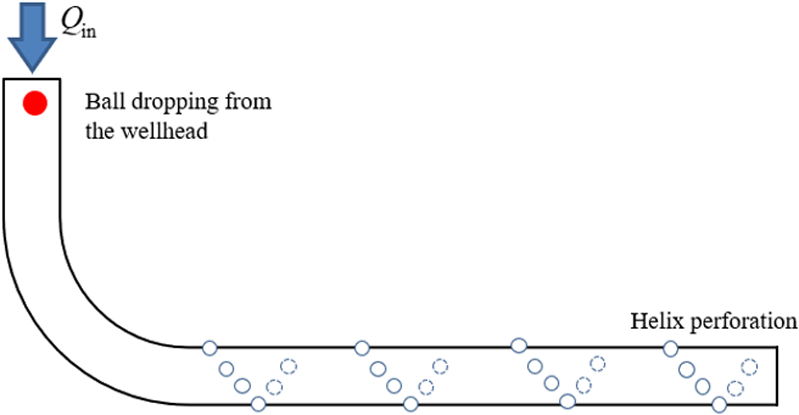
Sketch of dropping a ball sealer from the wellhead of horizontal well.
Forces of ball transportation
If the flow field of fracturing fluid containing particles is not perturbed by the particles (Li et al., 2005), the ball sealer velocity in the axial direction is

The density of the ball sealer is typically greater than that of the fracturing fluid because the ball sealer is often dropped from the wellhead and down the casing to the well bottom. Once a ball-sealer is dropped from the wellhead, it suffers many kinds of forces (Figure 2), including gravitational, buoyancy, frictional and resistance forces.
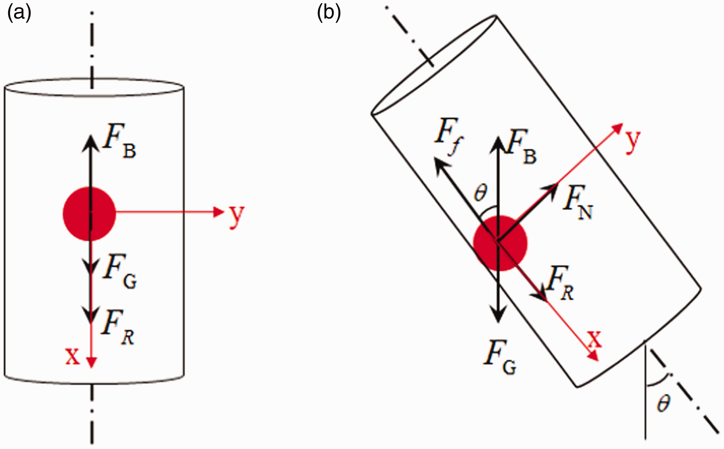
Force acting on a ball sealer when dropping.
The gravitational force of a ball sealer is

The buoyancy force of a ball-sealer inside the fracturing fluid is

It is generally assumed that there is no contact force between the ball sealer and casing well in a vertical well, so any friction induced by the casing wall can be ignored. However, in inclined wells or horizontal wells, the friction between the ball sealer and the casing wall cannot be ignored. A general equation to compute this friction is

A ball sealer is also subject to a resistance force, which is relevant to the relative motion of the ball sealer and fracturing fluid. An additional resistance force acting on a ball sealer in the casing may exist due to the presence of confining boundaries. The severity of this phenomenon, named the wall effect is ignored in this paper because the ball-casing diameter ratio is very close to zero according to previous studies (Chhabra et al., 2003; Nozaki et al., 2011). Thus, the resistance force induced by the viscous fluid acting on the ball sealer is

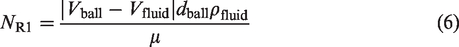
In equation (5), the Reynolds number is
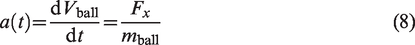
In the direction of the wellbore axis, the resultant force in the x-axis is

According to Newton’s second theorem, the acceleration of the ball sealer is
Integrating the acceleration, the velocity of the ball sealer is
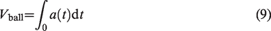
when a(t) = 0, the ball sealer reaches a stable state of constant speed.
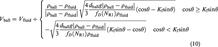
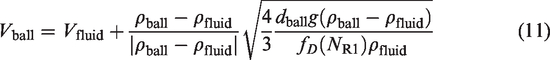
In the vertical well section, the final velocity of the ball sealer when reaching a stable state is
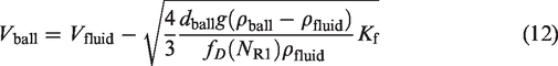
In the horizontal section, the final velocity of ball sealer when reaching a stable state is
After the ball sealer is dropped from the wellhead, the trajectory of the ball sealer is
The initial conditions of the ball position and velocity are

Forces acting on the seating ball
To divert the ball sealer from the wellbore axis down the casing and to seat a perforation hole (Figure 3), the axial velocity of the ball sealer must be reduced to zero over a distance of approximately 1 pipe diameter. The work done by the inertial force is equal to the kinetic energy of the ball sealer

Force acting on the ball sealer when diverting to the perforation hole.
Force acting on the ball sealer when diverting to the perforation hole.
The inertial force that overcomes the velocity reduction is (Brown et al., 1963)
It is assumed that the fracture fluid is distributed equally to each perforation hole in the same perforation cluster. The velocity of fluid flowing through each perforation hole is

The drag force acting on the ball sealer tends to divert it from the axial flow channel towards the perforation hole. The fracturing fluid velocity varies from Vfluid to Vperf within a very short distance. According to the Bernoulli equation, the drag force is

Nozaki et al. (2013) defined a ratio of Fd to FI as an index to show the seating probability in a vertical well. In this paper, we define a diverting index, which is a ratio of lateral force to axial force, as follows
The drag force tending to unseat the ball sealer from the perforation hole is created by the fracturing fluid drag upon the exposed portion of the ball. The unexposed area of the ball inside the perforation is neglected once the ball sealer seats on the perforation hole. The velocity of the streamline decreases from Vfluid to zero when hitting the seated ball sealer. According to the Bernoulli equation, the drag force tending to unseat the ball is (Brown et al., 1963)

Fu is the unseating force, N. In equation (21), the Reynolds number is
The force holding the ball sealer on the perforation hole is proportional to both the pressure differential across the perforation hole and the area of the perforation. The holding force (Brown et al., 1963) is

To ensure that the ball sealer remains seated, the lateral force must exceed the axial force. Hence, we defined a seating force as follows.

To remove the ball sealer from the perforation, the unseating force must exceed the axial vector of lateral force. Then

We should recognize the probability of a second ball hitting the seated ball because all the balls travel down the casing.
Case analysis
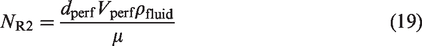
A practical well trajectory is illustrated in Figure 5. The length of the horizontal wellbore is approximately 1500 m. The total depth is 5960 m. The perforation interval in the first stage ranges from 5960 to 5900 m, including six perforation clusters. The spacing of perforation cluster is 8–10 m. Each perforation cluster contains eight perforation holes. The other parameters are listed in Table 1.
Practical well trajectory of a horizontal well.
Related parameters in the study case.
The velocity of a ball sealer after its dropping increases very fast and achieves terminal velocity in the vertical borehole within a few seconds in this example (Figure 6). This agrees well with Li’s model (Li et al., 2005). The positive direction of the resistance force acting on the ball sealer is consistent with the flowing direction of the fracturing fluid, which accelerates the ball sealer down to the well bottom. The ball sealer reaches a stable dropping state when the velocity reaches terminal velocity.
The ball velocity vs. dropping time in the vertical borehole section. The casing injection rate is 6 m3/min.
If the ball sealer is heavier than the fracturing fluid, the terminal velocity of the ball sealer in the vertical borehole section is greater than the flowing velocity of the fracturing fluid (the black line in Figure 7). The positive direction of the resistance force acting on the ball sealer is opposite to the flowing direction of the fracturing fluid, which balances the resultant force of the gravity and buoyancy forces. In contrast, if the ball sealer is lighter than the fracturing fluid, its terminal velocity in the vertical borehole is less than the flowing velocity of the fracturing fluid, and the resistance force acting on the ball sealer is consistent with the flowing direction of the fracturing fluid.
The terminal velocity of the ball sealer vs. its density. The casing injection rate is 6 m3/min.
In the horizontal borehole section (the inclination angle is strict 90°), the terminal velocity of a non-buoyant or buoyant ball sealer is less than the flowing velocity of the fracturing fluid (the red line in Figure 7). The resultant force of the gravity and buoyancy forces is perpendicular to the movement direction of the ball sealer and has no contribution in accelerating or slowing the ball movement in the horizontal borehole section. The resistant force induced by the viscous fluid acting on the ball balances with the frictional force induced by the contact with the casing wall.
According to the whole trajectory of a real horizontal well and the parameters in Table 1, the velocities of the ball sealers with different densities in the whole borehole are shown in Figure 8. In the vertical or horizontal borehole sections, the velocities are relatively stable. The fluctuation of velocity in the horizontal borehole section is induced by the fluctuation of deviation angle in a real well trajectory. When the density of the ball sealer is equal to the fracturing fluid’s density, the resultant force of gravity and buoyancy forces is zero. The velocity of the ball sealer is equal to the fracturing fluid’s velocity in the whole wellbore (excluding the onset of dropping the ball). In the build-up borehole section, the velocities of the non-buoyant or buoyant ball sealers tend to be close to the terminal ball velocity in the horizontal wellbore. Because the inclination angle in the horizontal wellbore section is slightly less than 90°, the ball velocity (yellow and purple lines in Figure 8) is still greater than the fracturing fluid velocity. There is no velocity contrast between the ball sealer and fracturing fluid in the stable state when their densities are strictly equal.
Ball velocity in the whole borehole. The casing injection rate is 6 m3/min.
According to equation (10), the ball velocities (named theoretical velocities) in the stable states versus the inclination angle under different ball densities are demonstrated by dashed lines in Figure 9. However, the ball velocity changes in relation with the continuously changing inclination angle. Hence, according to equation (9) and the wellbore trajectory, the numerical velocities are demonstrated in solid lines in Figure 9. The theoretical velocity agrees well with the numerical velocity.
Ball velocity in the build-up borehole section. The casing injection rate is 6 m3/min.
Under different perforation angles, the diverting index of a buoyant ball sealer (with density 800 kg/m3) is shown in Figure 10(a). The diverting index reaches the minimum value when the perforation angle is 180° because the resultant force of the buoyancy and gravity forces acts against the drag force induced by the perforation jet flow. By contrast, the diverting index reaches the maximum value when the perforation angle is 0°. Under different perforation angles, the diverting index of a non-buoyant ball (with density 1200 kg/m3) is shown in Figure 10(b). The diverting index reaches the maximum value when the perforation angle is 180° because the resultant force of the buoyancy and gravity forces acts consistent with the drag force induced by the perforation jet flow. The contrast between the maximum and minimum diverting index is much smaller than the drag force induced by the perforation jet flow. Hence, the drag force is a critical significant driving force in diverting the ball movement.
Diverting index under different perforation angles. The casing injection rate is 6 m3/min.
Under different ball densities and casing injection rates, the minimum diverting index of the ball sealer when penetrating through the perforation interval is shown in Figure 11. The diverting index decreases with increasing ball sealer density, which means that a buoyant ball sealer has a greater diverting probability and seating efficiency than a non-buoyant ball sealer. This law agrees well with Erbstoesser’s experiments (Erbstoesser, 1980). However, there is no obvious relationship between the minimum diverting index and casing injection rate. This indicates that the ball sealer density is a more critical parameter than the casing injection rate when the ball diverts to a perforation hole.
Diverting index vs. injection rate and density in the perforation interval.
Under different ball densities and casing injection rates, the minimum seating force acting on the ball sealer when seating the perforation hole is shown in Figure 12. The minimum seating force increases drastically with increasing casing injection rate, while it slightly decreases with increasing ball sealer density. It shows that the casing injection rate is a more critical parameter than the density when a ball seats on a perforation hole.
The index vs. injection rate and density in the perforation interval.
To improve the seating efficiency, a buoyant ball sealer associated with a higher injection rate of fracturing fluid is highly recommended. It is worth noting that the fracturing fluid is not equally distributed into the perforation holes because of stress interactions among the hydraulic fractures (Cheng et al., 2017a, 2017b, 2021). Our future work will consider the influence of the unequal distribution of fracturing fluid on the diverting and seating behaviours.
Conclusions
This paper analyse the theoretical forces acting on the dropping and seating behavior of a ball sealer. Based on a real horizontal well trajectory, the sensitivities of the ball sealer density, casing injection rate and perforation angle to the seating behaviours are simulated. Some interesting findings are noted as follows.
In the vertical wellbore section, the ball sealer accelerates very fast at the onset of dropping and reaches a stable dropping state within a few seconds. If the ball sealer is heavier than the fracturing fluid, its terminal velocity is greater than the fracturing fluid flowing velocity. If the ball sealer is lighter than the fracturing fluid, its terminal velocity is less than the fracturing fluid flowing velocity. In the horizontal wellbore section, the terminal velocities of the non-buoyant or buoyant ball sealers are less than the fracturing fluid flowing velocity. There is no velocity contrast between the ball sealer and fracturing fluid in the stable state when their densities are strictly equal. In the build-up borehole section, the velocities of the non-buoyant or buoyant ball sealers tend to be close to the terminal ball velocity in the horizontal wellbore. Under different perforation angles, the diverting index has the minimum and maximum values in the horizontal wellbore section, but their contrast is much smaller than the drag force. The drag force is the main driving force diverting the ball movement. The diverting index decreases drastically with increasing of ball sealer density, which indicates a buoyant ball sealer has a greater probability and seating efficiency than a non-buoyant ball sealer. There is no obvious relationship between the diverting index and casing injection rate. The ball sealer density is a more critical parameter than the casing injection rate when a ball diverts to a perforation hole. The minimum seating force increases drastically with increasing injection rate, while it slightly decreases with increasing of ball sealer density. This shows that the casing injection rate is a more critical parameter than the ball sealer density when a ball seats on a perforation hole. A buoyant ball sealer associated with a higher injection rate of fracturing fluid is highly recommended for improving the seating efficiency.
Footnotes
Declaration of conflicting interests
The author(s) declared no potential conflicts of interest with respect to the research, authorship, and/or publication of this article.
Funding
The author(s) disclosed receipt of the following financial support for the research, authorship, and/or publication of this article: This research was supported by the National Natural Science Foundation of China (No. 41802195 and No. 52074250).