
Abstract
China has hundreds of thousands of oil and water wells, about 30% of which have been abandoned currently. If we can convert abandoned wells into geothermal wells, it will save lots of money and reduce drilling and completion time greatly. In this paper, six enhanced geothermal system (EGS) well layout schemes are proposed based on the utilization of abandoned oil–water wells and common oilfield well pattern. Here six common injection-production well patterns in oilfield are combined to hot dry rock (HDR) production and the heat extraction performance is simulated. The results show that the injection well number and the location of injection wells have critical influence on the heat extraction performance. Under the same total injection mass flow rate, the injection well number is the key factor and the fracture area is the secondary factor on heat extraction when the HDR energy is enough. For electricity generation, the life span is 20.2, 19.2, 19.0, 19.2, 18.2 and 13.9 years, and the heat extraction ratio is 65.83, 57.35, 65.96, 62.79, 59.30 and 43.09% from case 1 to case 6, respectively. For heating demand, the life span is 30.0, 30.0, 29.9, 30.0, 29.8, and 27.7 years, the heat extraction ratio is 78.91, 69.63, 77.02, 75.92, 72.27 and 58.94% from case 1 to case 6, respectively. The total injection mass flow rate and injection temperature also have a negative effect on the heat extraction performance. Case 1 (row parallel well layout), Case 3 (four-spot well layout) and Case 4 (five-spot well layout) are a good choice both for electricity generation and heating demand. This study provides good guidance for the selection and optimization of different EGS well layout.
Keywords
Introduction
In recent years, with the increase of energy consumption and the intensification of greenhouse effect, clean energy plays an increasingly important role in the energy field (Ahmadi et al., 2018; Ramezanizadeh et al., 2019). Hot Dry Rock is a kind of deep geothermal resource which is clean renewable and widely distributed (Li et al., 2019; Lu, 2018; Wang et al., 2019. Compared with solar, wind and tidal power, the exploitation of HDR is less affected by the environmental factors (Li et al., 2015; Zhang et al., 2019). EGS extracts heat from HDR reservoir through fluid injection and it is considered to be an important way to exploit HDR (Moya et al., 2018). Considering the environmental impacts and economic benefits, EGS is considered to be the best way for electricity generation (Xu et al., 2018). However, the establishment of EGS is a costly and complicated engineering system, and reducing the cost and difficulty is an important way to accelerate the HDR development (Pan et al., 2019).
China has hundreds of thousands of oil and water wells, about 30% of which have been abandoned currently (Bu et al., 2012). If we can convert abandoned wells into geothermal wells, it will save lots of money and reduce drilling and completion time greatly (Caulk and Tomac, 2017; Cheng et al., 2014; Davis and Michaelides, 2009). At the same time, the extracted heat can be used for oil exploitation and transportation and power supply for nearby oilfields (Kharseh et al., 2019). Moreover, there is a strong correlation between geothermal and oil–gas production. The data information of oil and gas exploration, drilling, completion and exploitation can be used for geothermal development and utilization (Nian and Cheng, 2018; Yang et al., 2017). In this paper, six EGS well layout schemes are proposed based on the utilization of abandoned oil–water wells and common oilfield well pattern. Six common injection-production well pattern in oilfield are combined to HDR production and the heat extraction performance is simulated.
A proper selection of well layout may reduce the development cost and increase the heat extraction ratio (Ding and Wang, 2018; Li and Zhu, 2018). The heat extraction performance of many kinds of well layout has been investigated currently. Yang and Yeh (2009) modeled the heat energy extraction performance in a triplet well layout and demonstrated that the well spacing, well radius, reservoir thickness and injection mass flow rate affect the heat extraction ratio significantly. Chen and Jiang (2015) simulated the heat extraction performance of doublet, triplet, quintuplet well layout and found that simply increasing the production well number does not improve the heat extraction performance of EGS, and triplet well layout can perform better than quintuplet well layout or worse than an EGS with the standard doublet well layout. Xia et al. (2017) simulated horizontal doublet well layout in which parallel injection and production wells are connected by a set of single large wing fractures, and proposed that 40 equidistant fractures along 1.2 km long parallel well section with well distance of 500 m would meet the industrial production-level system. There are many single-well geothermal systems, such as heat pipe single well (Huang et al., 2018), multilateral-well (Shi et al., 2019), tree-shaped wells (Liu et al., 2019), U-tube downhole (Lyu et al., 2018), and so on (Yan et al., 2019).
Although the previous simulation studies on heat extraction performance of different well layout are extensive, there is lack of a thorough and comprehensive comparison on heat extraction of application of oilfield injection scheme in HDR well layout. In this paper, the heat extraction performance of different well layout was investigated on the basis of the recovery and utilization of abandoned oil and water wells. Based on the injection scheme in oilfield, six ideal models for the HDR heat extraction are proposed. A thermal-hydraulic model is established to investigate the heat extraction performance of different well layout. Based on the model, the temperature distribution, pressure distribution, average production temperature, life span, average rock temperature and heat extraction ratio are proposed to evaluate the heat extraction performance of different well layout. The heat extraction performance of different well layouts is compared and the effects of injection mass flow rate and injection temperature on the heat extraction performance are studied. This study provides good guidance for the selection and optimization of different EGS well layout.
Methodology
Model assumptions
In this work, we focus on the heat extraction performance of EGS under different combination of fracture and well array. The computational model includes the following assumptions:
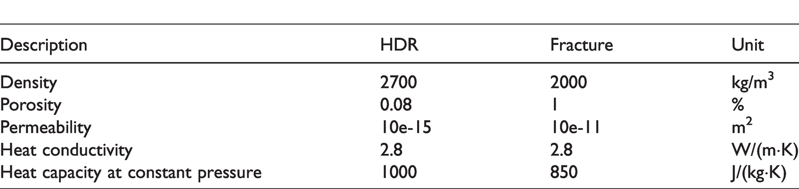
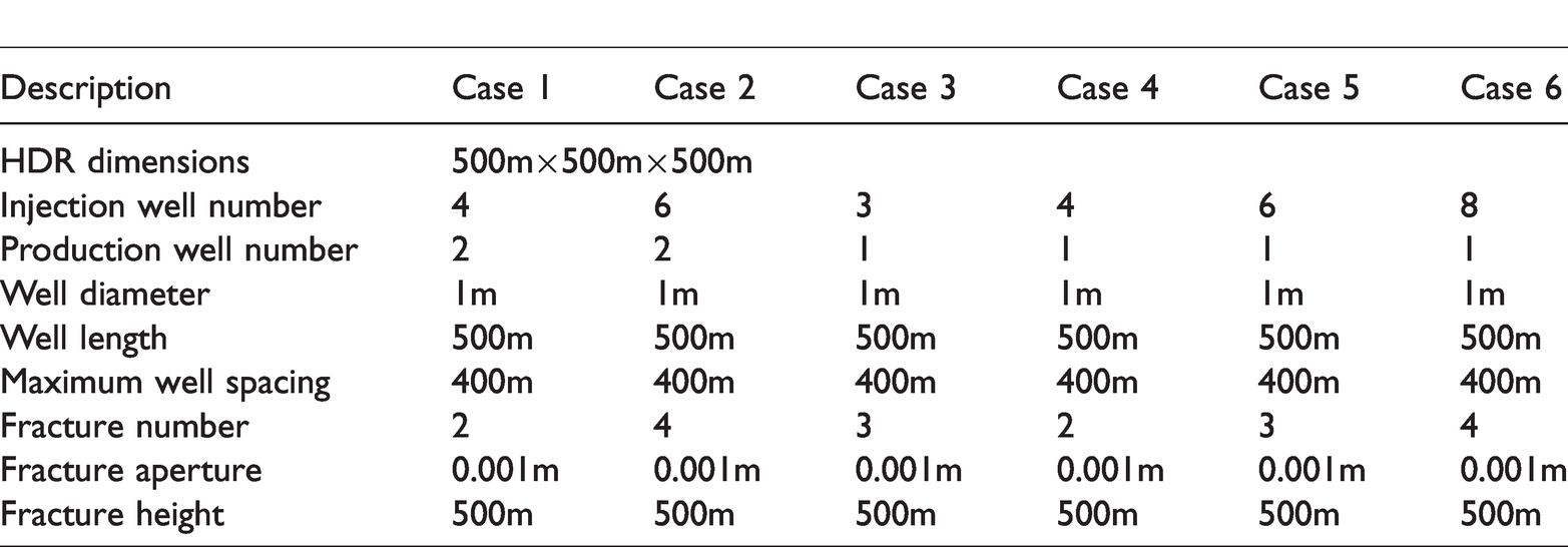
The HDR reservoir rock is homogenous and isotropic. The density, porosity, permeability, heat conductivity and heat capacity at constant pressure of HDR reservoir rock are considered to be constant under the heat extraction condition. The HDR reservoir is saturated with water before the heat extraction operation. The water remains in liquid state under the heat extraction condition, because the pressure and temperature meet the conditions of to keep it in liquid state (the specification of water phase diagram see Figure 1). The density, dynamic viscosity, heat conductivity and heat capacity at constant pressure of water change with temperature (see Figures 2 to 5). The permeability of the rock matrix is relatively lower, almost impermeable. Assume there is a fracture between each injection well and production well as the key heat extraction channel. The fracture penetrates through the computational reservoir along, corresponding to the injection well and production well. The maximum distance among the injection well keeps consistent under different well layouts. The reservoir descriptions of computational model are shown in Table 1.
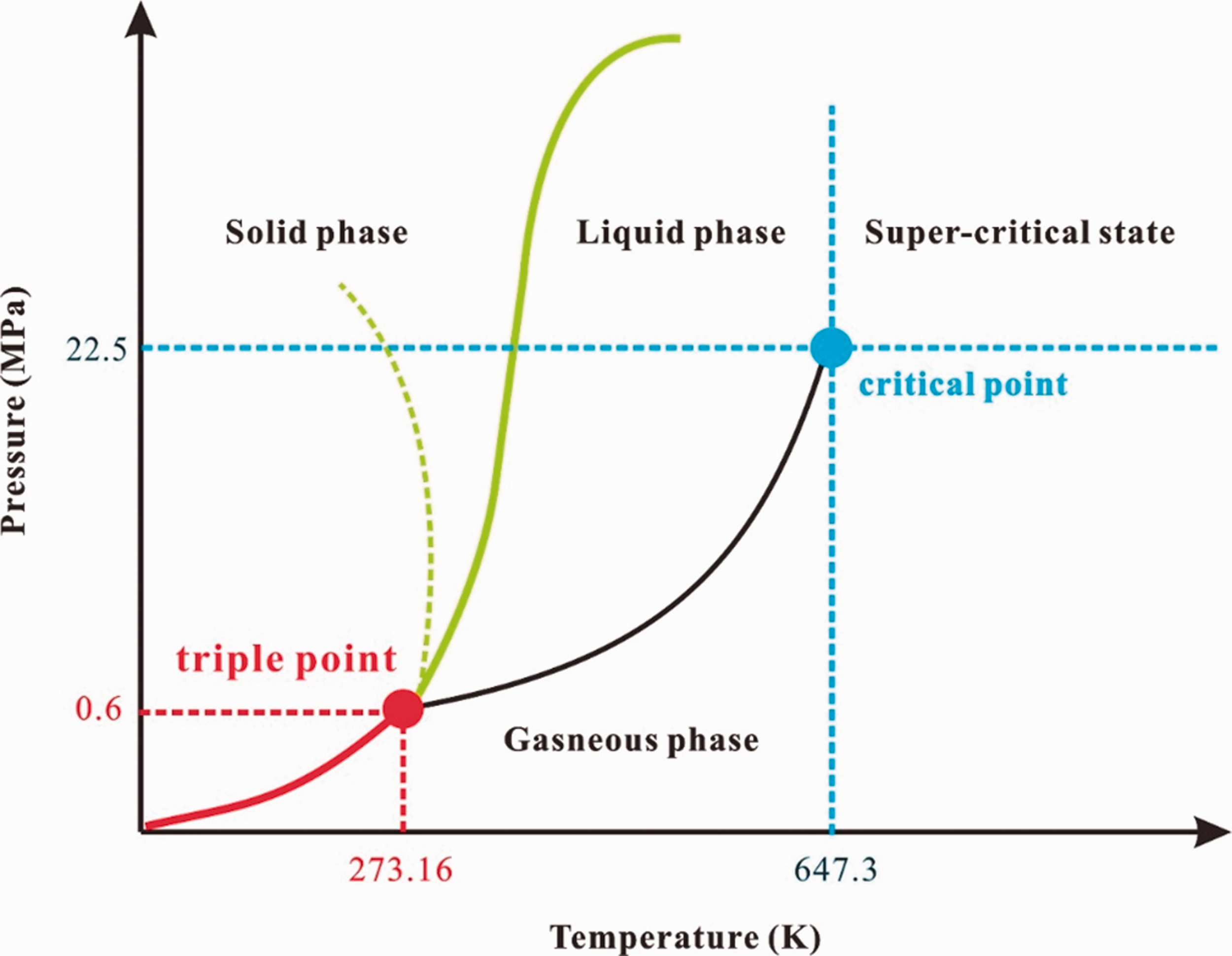
The pressure–temperature phase diagram of water.
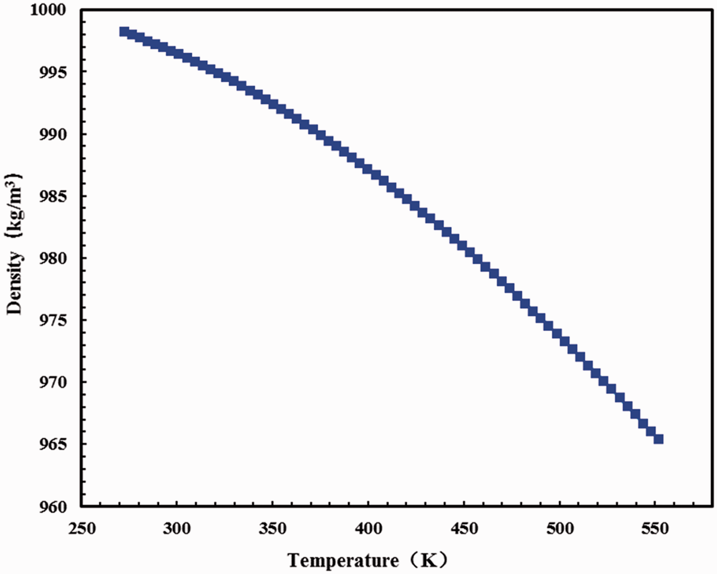
Variation curve of water density with temperature.
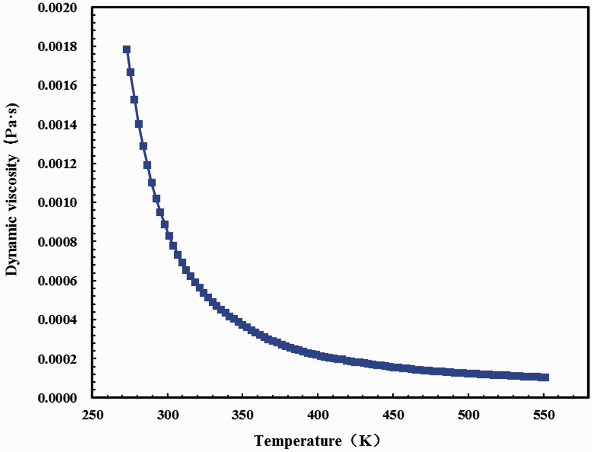
Variation curve of water dynamic viscosity with temperature.
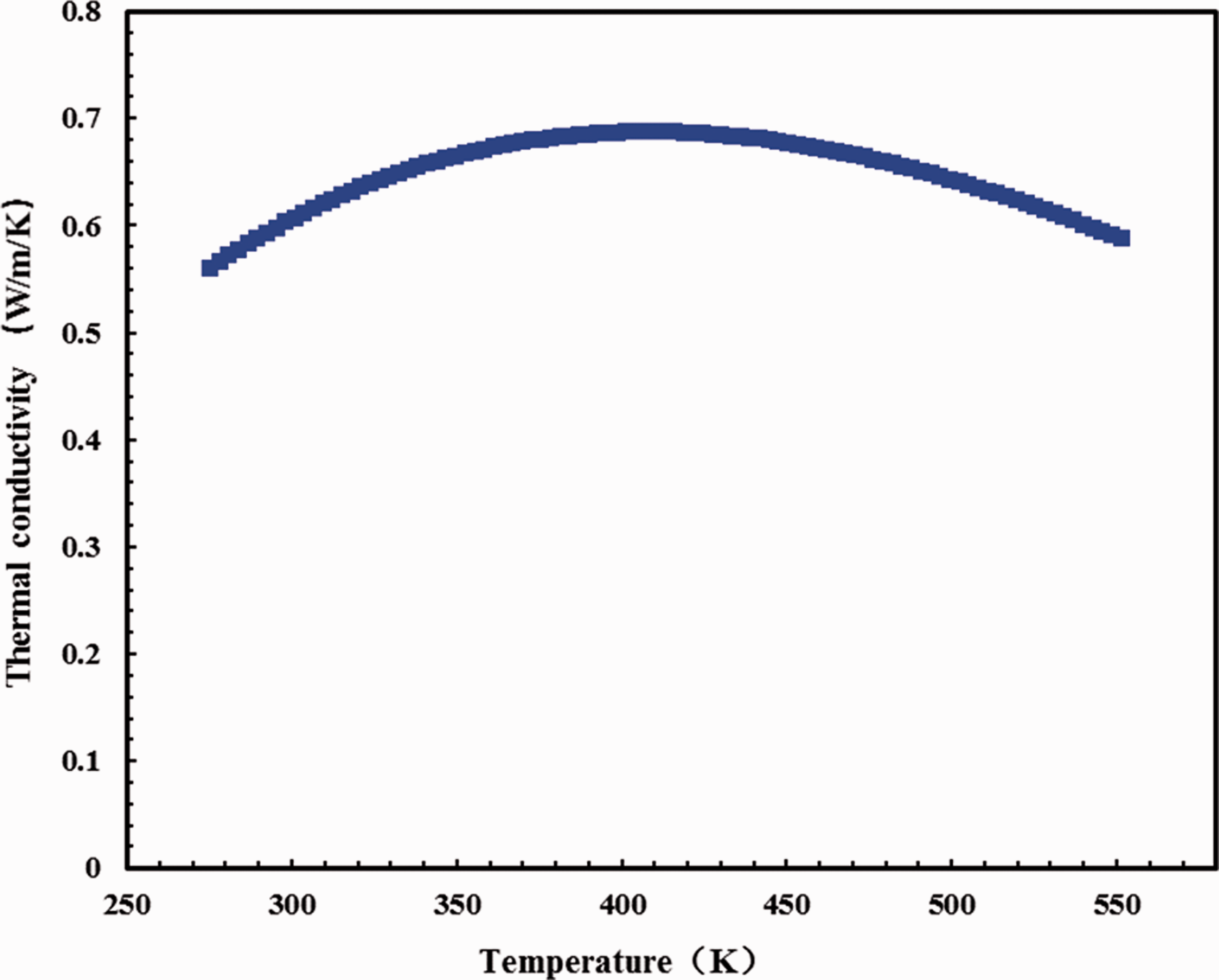
Variation curve of water thermal conductivity with temperature.
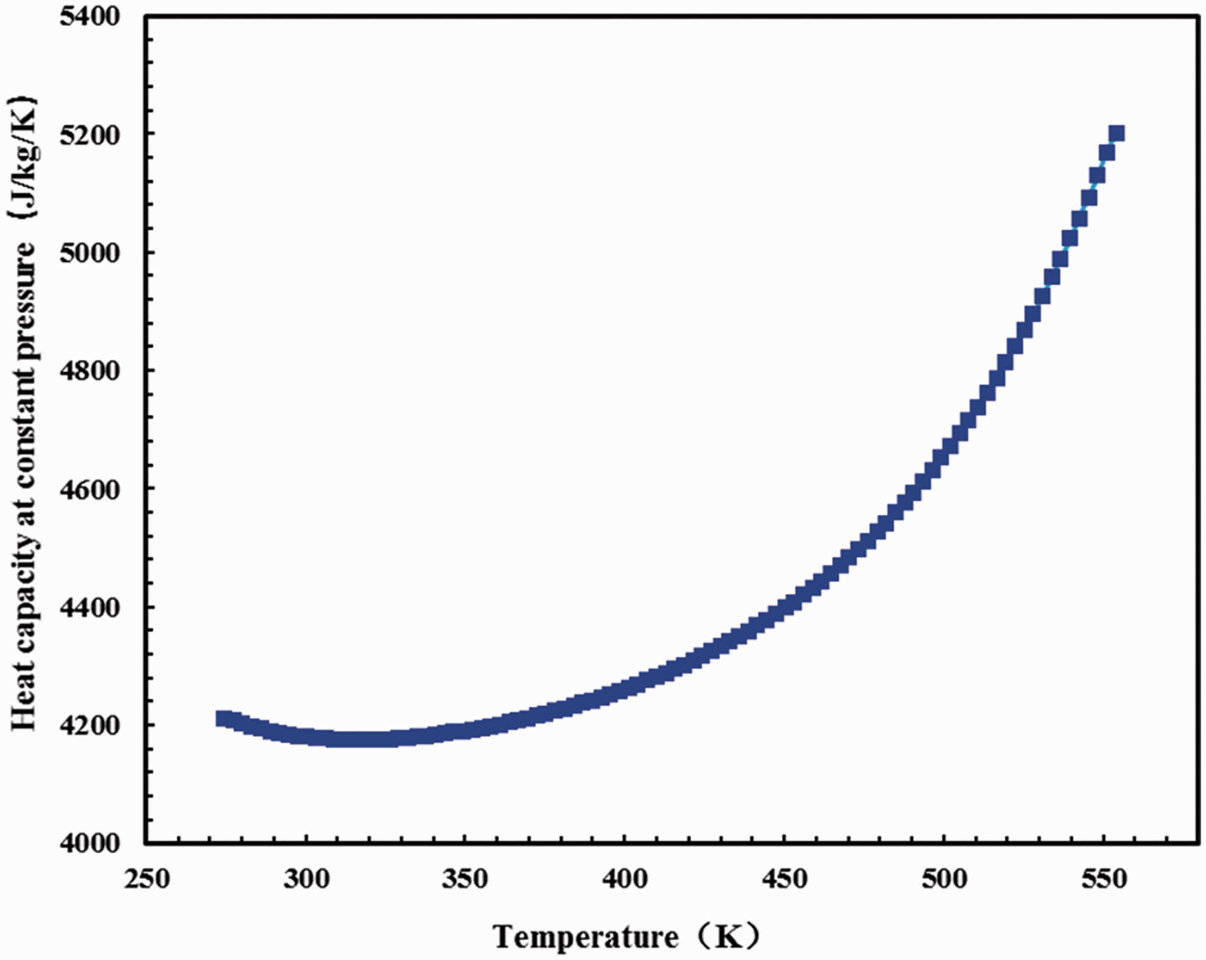
Variation curve of water heat capacity at constant pressure with temperature.
The reservoir descriptions of computational model.
Mathematical equations
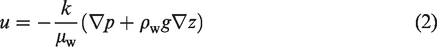
The flow of water is laminar flow and subject to Darcy’s law. First, according to the mass conservation equation and Darcy law, the water flow in the porous media and the Darcy seepage velocity 
The rock matrix is regarded as elastic porous storage and the effect of pressure on porosity is considered as
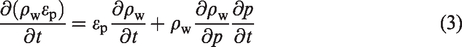
According to the state equation of the rock matrix, the rock compressibility can be described as
Define 
Substituting equations (2) to (5) into equation (1), the seepage field equation of water in the porous media is obtained as

Similarly, the seepage field equation of water in the fracture can be expressed as

From previous studies (Cao et al., 2016; Jiang et al., 2014), the local thermal equilibrium is applicable under the condition of the heat transfer coefficient; the area is relatively large, and the fracture aperture is relatively small. Therefore, in this work the local thermal equilibrium theory is adopted to investigate the temperature field.
According to the energy conservation equation, the heat transfer process in the porous media can be described as (Saeid et al., 2013; Xu et al., 2015)


Similarly, the heat transfer process in the fracture can be described as

Model and parameters under different well layout
In this work, six ideal models are established for the HDR heat extraction according to the oil field well layout. The case 1 is row opposite well layout, two production wells in the middle of reservoir and four injection wells are located on opposite sides to the production well. The case 2 is row cross well layout, two production wells in the middle of reservoir and six injection wells cross with the production wells on both sides. The case 3 is four-spot well layout, three injection wells are located at the apex of an equilateral triangle with a side length of 400 m and the production well is located at the center of the triangle. The case 4 is five-spot well layout, four injection wells are located at the apex of a square with a side length of 400 m and the production well is located at the center of the square. The case 5 is seven-spot well layout, six injection wells are located at the apex of the hexagon with a side length of 200 m and the production well is located at the center of the hexagon. The case 6 is nine-spot well layout, eight injection wells are located at the apex and midpoint of the square with a side length of 400 m and the production well is located at the center of the square. The six models differ greatly in well layout, but there are common points among different models. First, for each model, there is a fracture between each injection well and production well as the key heat extraction channel, and the fracture penetrates through the reservoir along corresponding the injection well and production well. Second, the maximum distance among the injection well keeps consistent under different well layout and the maximum distance is set as 400 m in this work.
The schematic of different well array and the computational model is shown in Figures 6 and 7, respectively. The specific spatial descriptions of computational model are shown in Table 2.
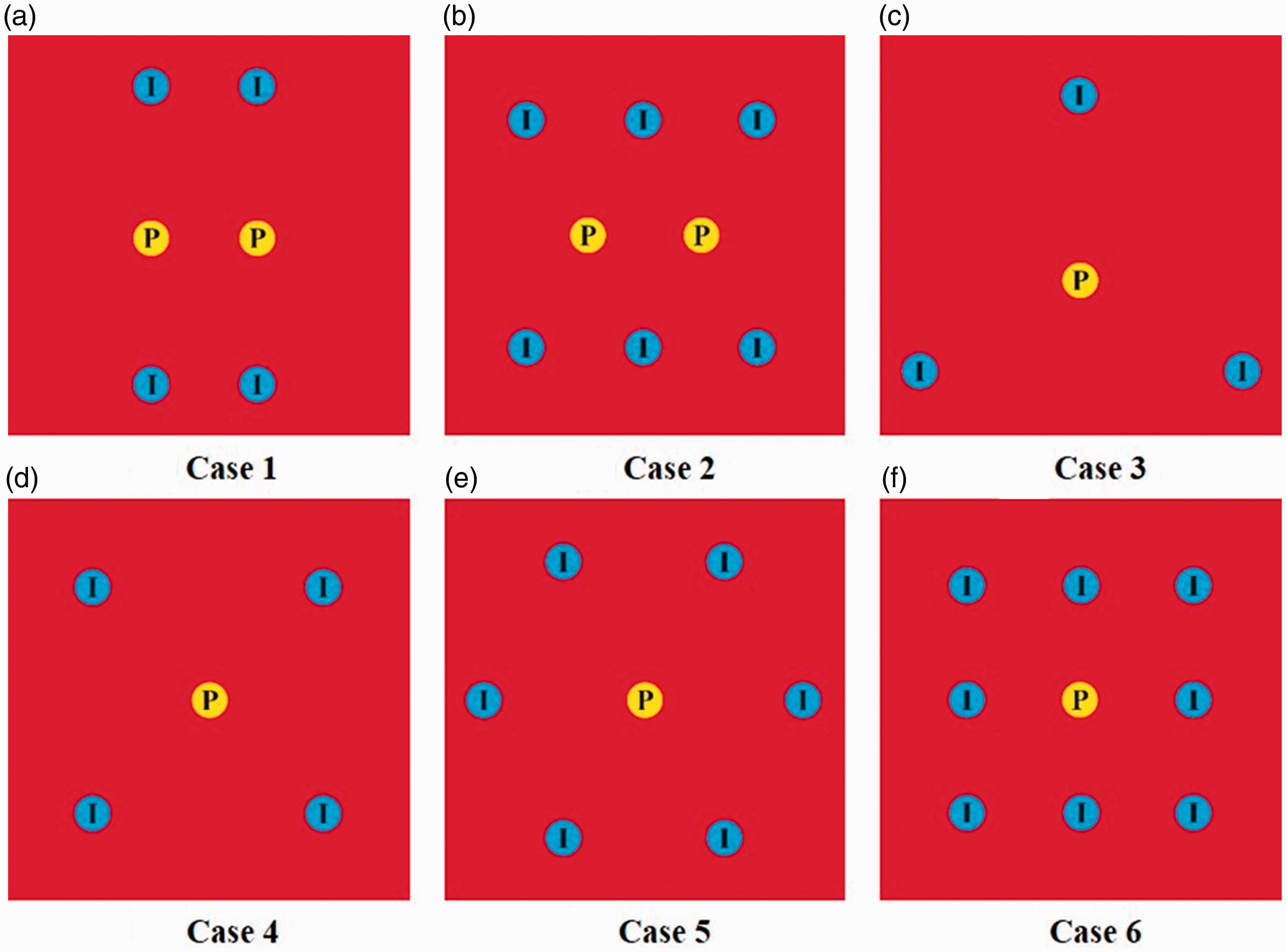
Schematic of different well array.
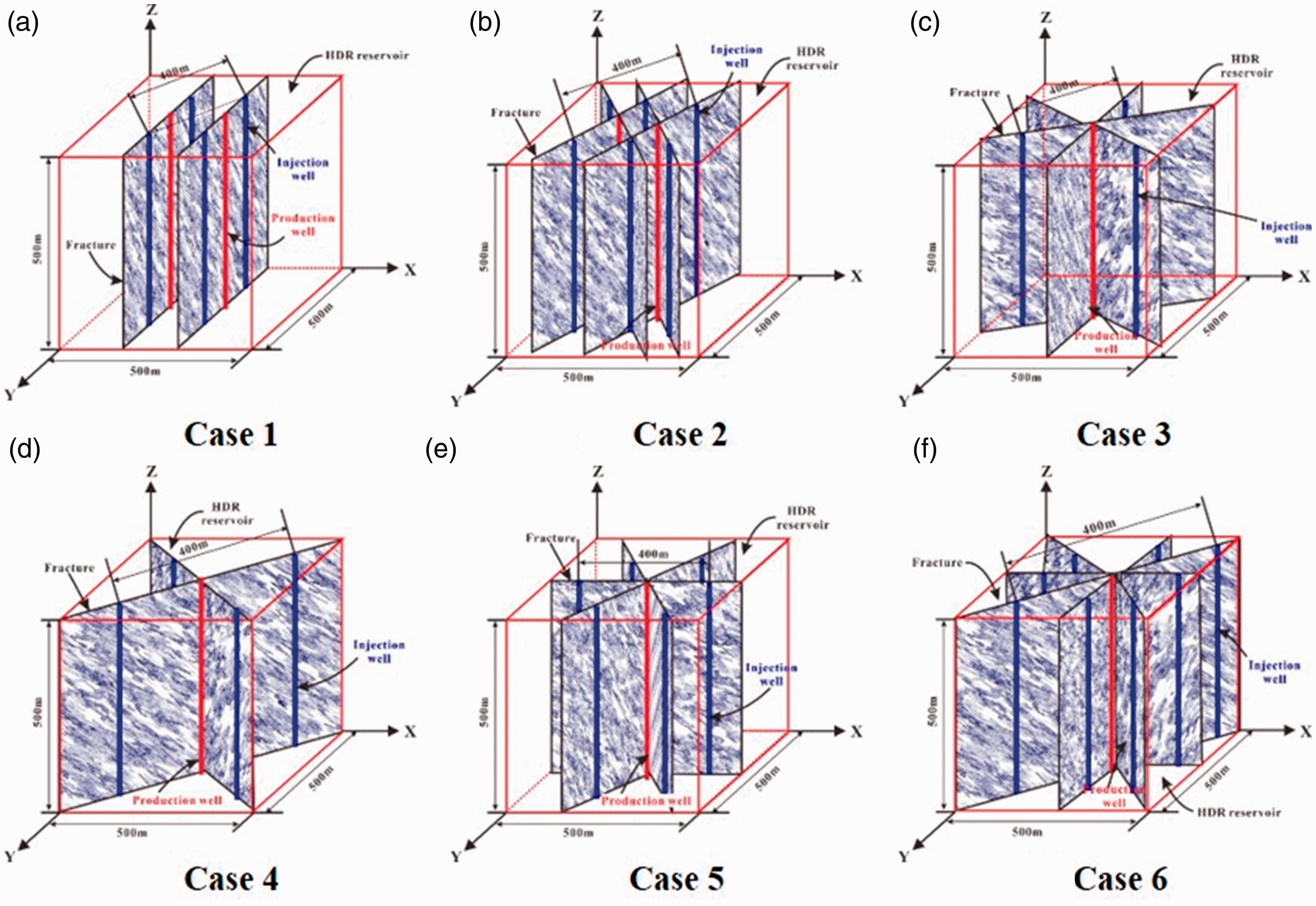
Schematic of the computational model.
The spatial descriptions of computational model.
The computational model mentioned above is adopted to simulate the heat extraction process of different well layout. The specific initial and boundary conditions are shown as below:
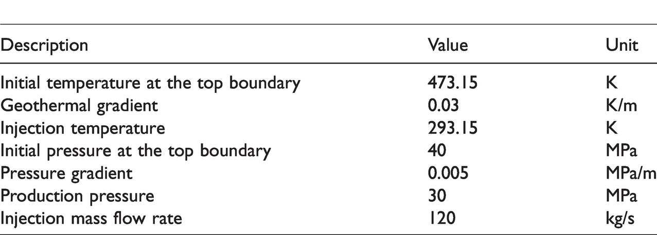
The HDR reservoir rock initial temperature at the top is 473.15 K. The temperature increases linearly with the depth and the geothermal gradient is 0.03 K/m. The initial temperature of other outer boundaries can be calculated by the initial temperature at the top and the geothermal gradient. The outer boundaries are set as thermal insulation. The HDR reservoir rock initial pressure at the top is 40 MPa. The pressure increases linearly with the depth and the pressure gradient is 0.005 MPa/m. The initial pressure of other outer boundaries can be calculated by the initial pressure at the top and the pressure gradient. The production pressure is set to 30 MPa. The injection wells are set as inlet boundaries. The injection temperature is set as 293.15 K and the injection mass flow rate is set as 120 kg/s. The production wells are set as outlet boundaries. The production pressure is set as 30 MPa.
The specific descriptions mentioned above can be seen in Table 3.
The corresponding descriptions of initial and boundary conditions.
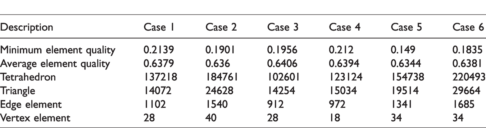
In order to guarantee the same simulation condition, the same principle is adopted to mesh computational model under different well layout. All the domains adopt the free tetrahedral mesh. For the injection and production wells adopt the extra fine mesh and the maximum element size is 4 m. The other domain adopts the fine mesh. The specific mesh descriptions of different well layout can be seen in Table 4. The mesh diagram of different well layout is shown in Figure 8, and the legend represents the element size.
Mesh of different well layout.
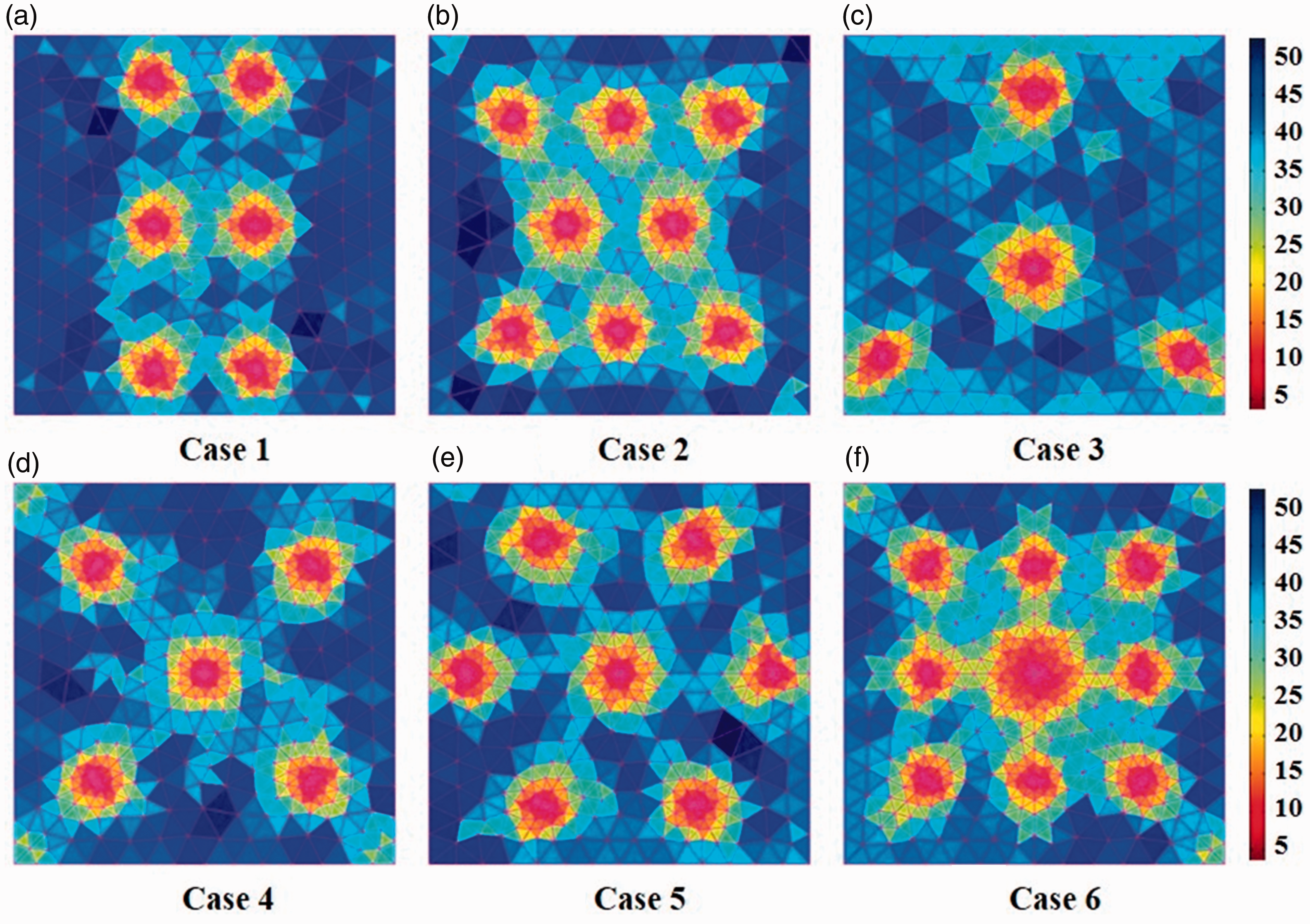
Mesh diagram of different well layout.
Results and discussion
Temperature and pressure distribution
In this section, the heat extraction performance of different well layout is compared under the total injection rate is 120 kg/s. Figures 9 and 10 illustrate the temperature and pressure distribution of different well layout at the 30th year. It can be observed that the heat extraction ratio and thermal residual position are different from case 1 to case 6. The production pressure keeps at 30 MPa and the injection pressure is much higher than production well to guarantee the fluid flow.
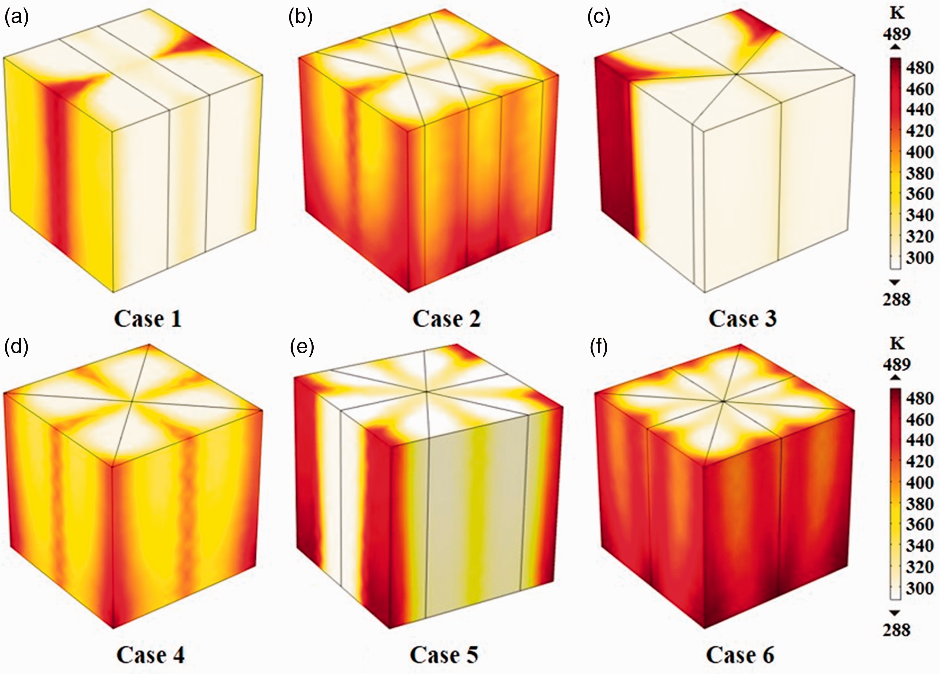
Temperature distribution of different well layout in the 30th year.
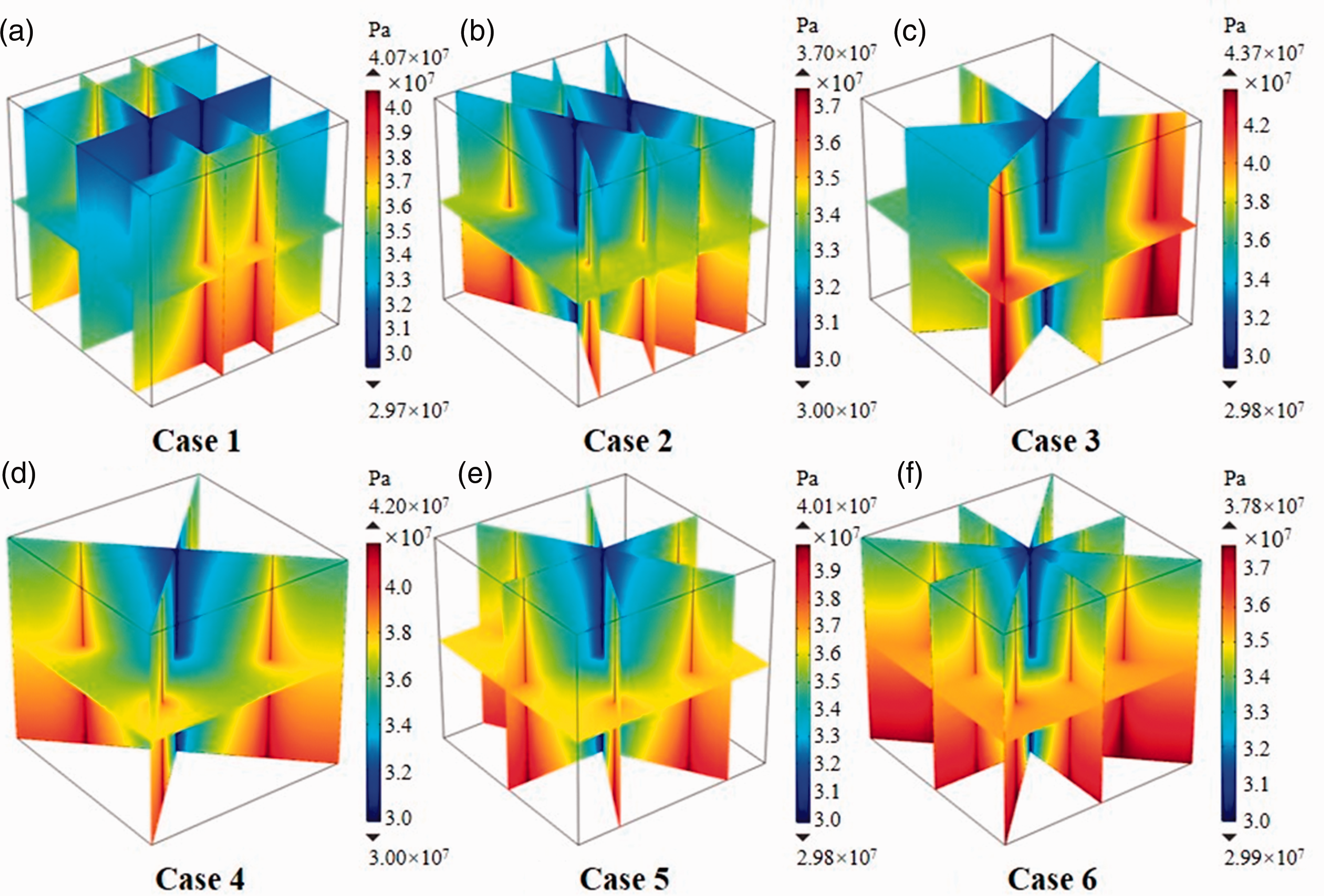
Pressure distribution of different well layout in the 30th year.
Since the total injection mass flow rate is the same, it can be speculated that the difference in temperature and pressure distribution is mainly caused by the combination of different well layout and fractures.
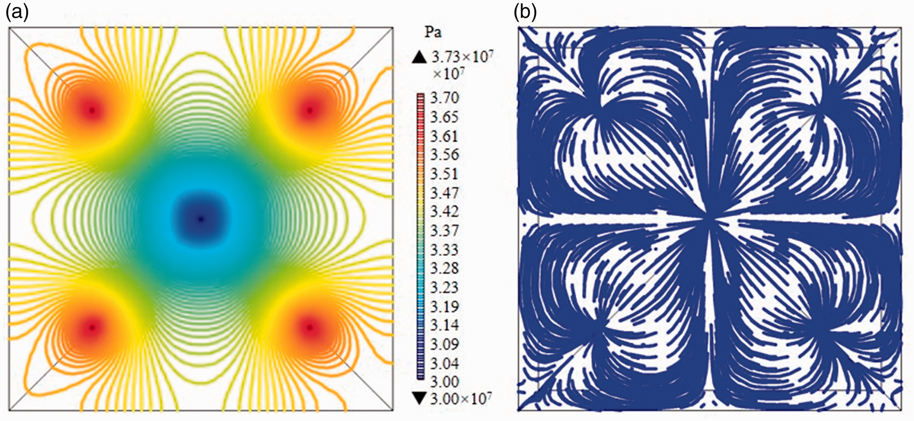
The Darcy velocity field and pore pressure field on x-y plane of case 1 is shown in Figure 11. From Figure 11, it is found that the streamline and pressure contour near injection and production well are much denser than the rest of the region. It indicates that the vicinity of injection and production well has higher velocity gradient and pressure gradient. Moreover, the pressure contours near the injection and production well are concentric circles, concluding that the wells are essentially boundaries of uniform pressure.
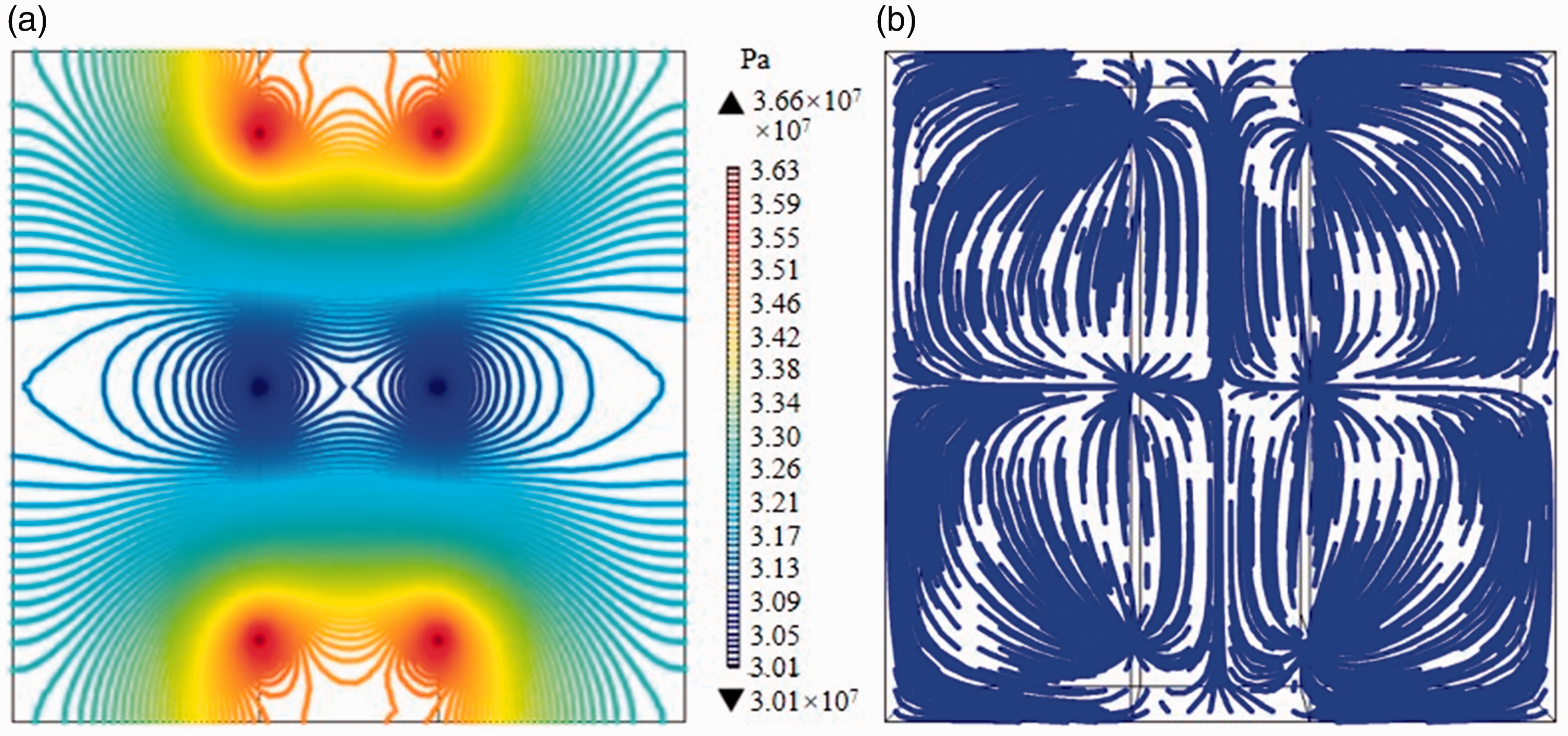
(a) Pressure contour; (b) streamline of Case 1 in the 30th year.
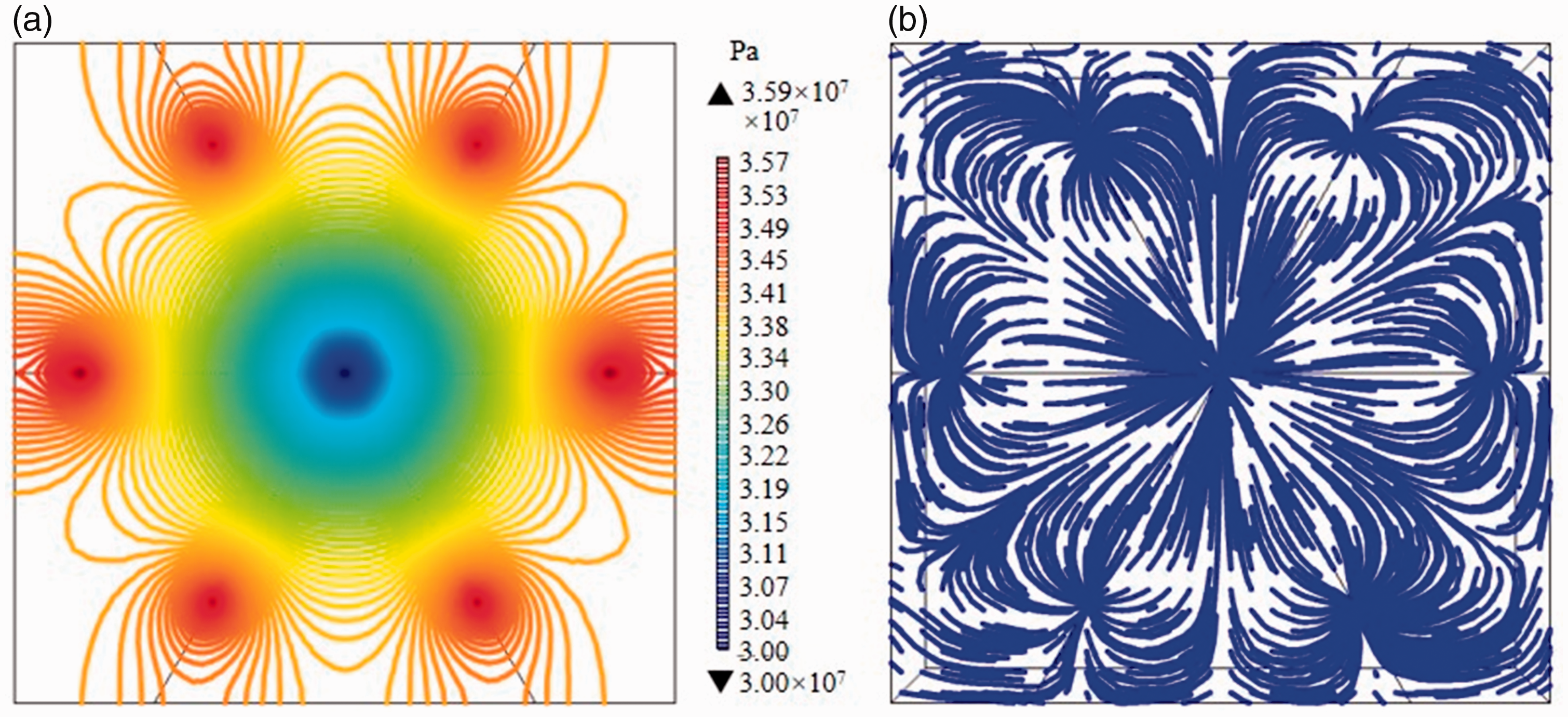
Driven by the pressure difference, working fluid flows from the injection well, through the rock matrix and fractures into the production well, and thus the HDR heat extraction process can be realized. Comparing Figure 11(a) and (b), it is found that where the pressure gradient small, the fluid flow velocity is small, which indicates that the fluid flow velocity mainly depends on the pressure gradient. Comparing Figures 8 and 11, it is found that the thermal residual region of case 1 is where both the pressure gradient and the fluid flow velocity are small. The law is also applicable to case 2 to case 6 and the pressure contour and streamline of case 2 to case 6 are shown in Figures 12 to 16. From above, it can be concluded that the injection well number and the location of injection wells have critical influence on the thermal extraction performance. It is necessary to choose proper well layout according to actual demand.
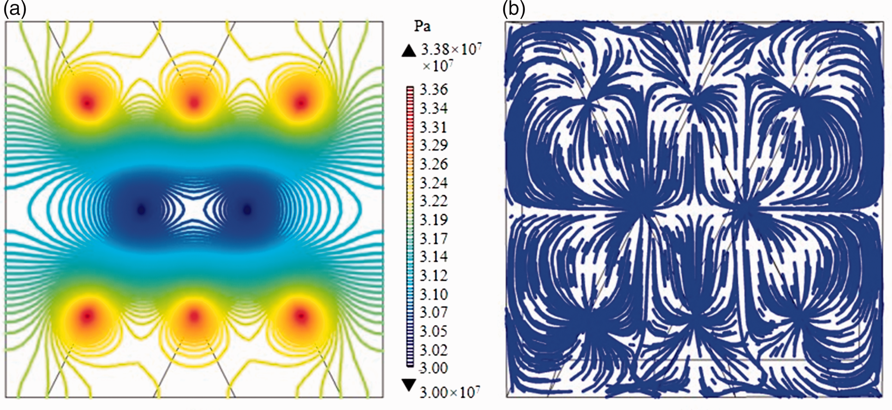
(a) Pressure contour; (b) streamline of Case 2 in the 30th year.
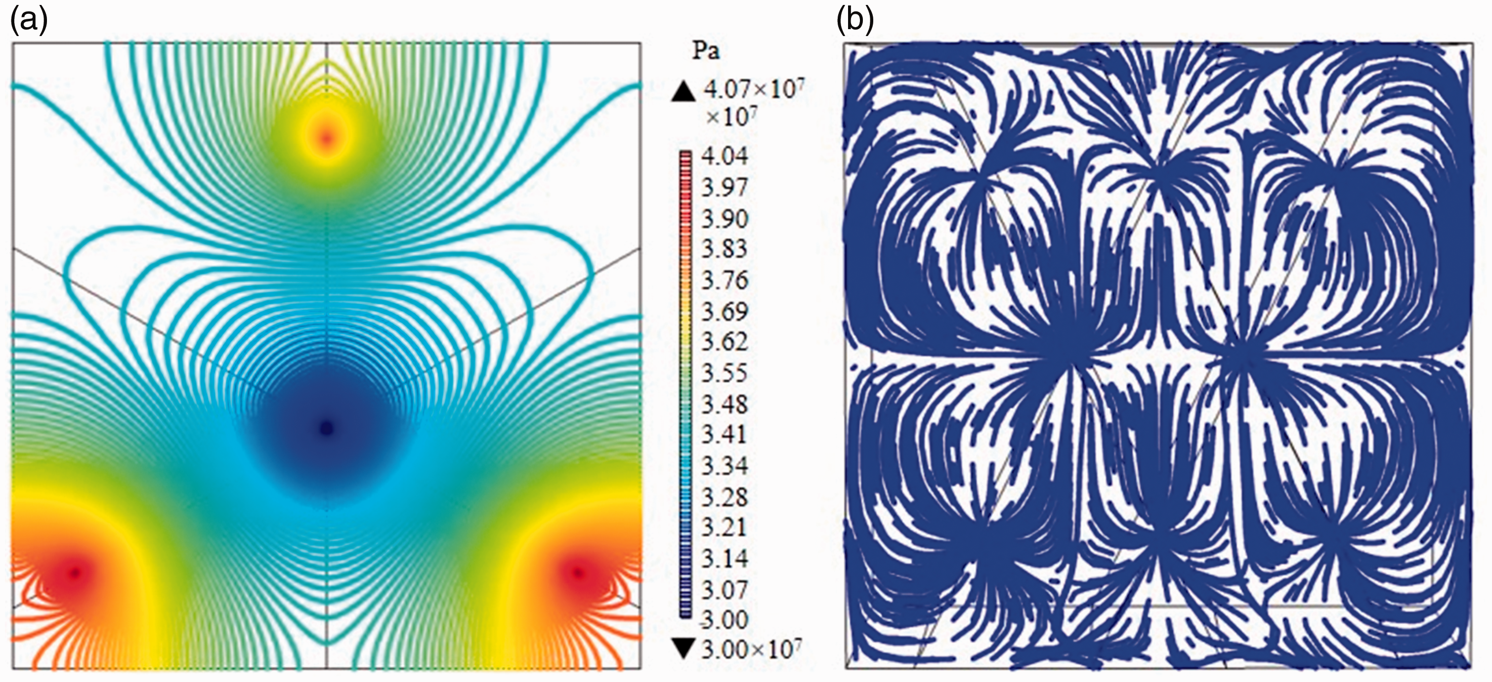
(a) Pressure contour; (b) streamline of Case 3 in the 30th year.
(a) Pressure contour; (b) streamline of Case 4 in the 30th year.
(a) Pressure contour; (b) streamline of Case 5 in the 30th year.
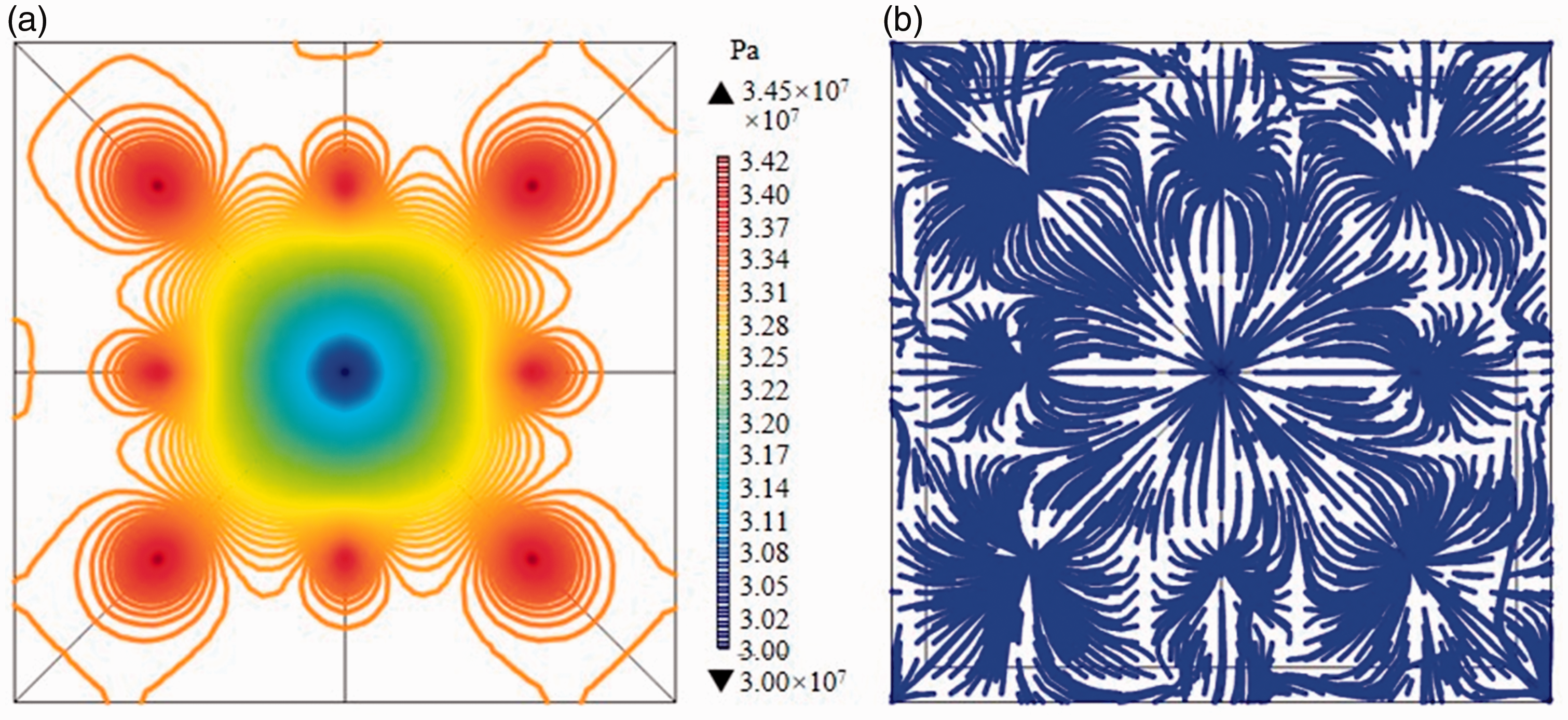
(a) Pressure contour; (b) streamline of Case 6 in the 30th year.
Average production temperature and life span
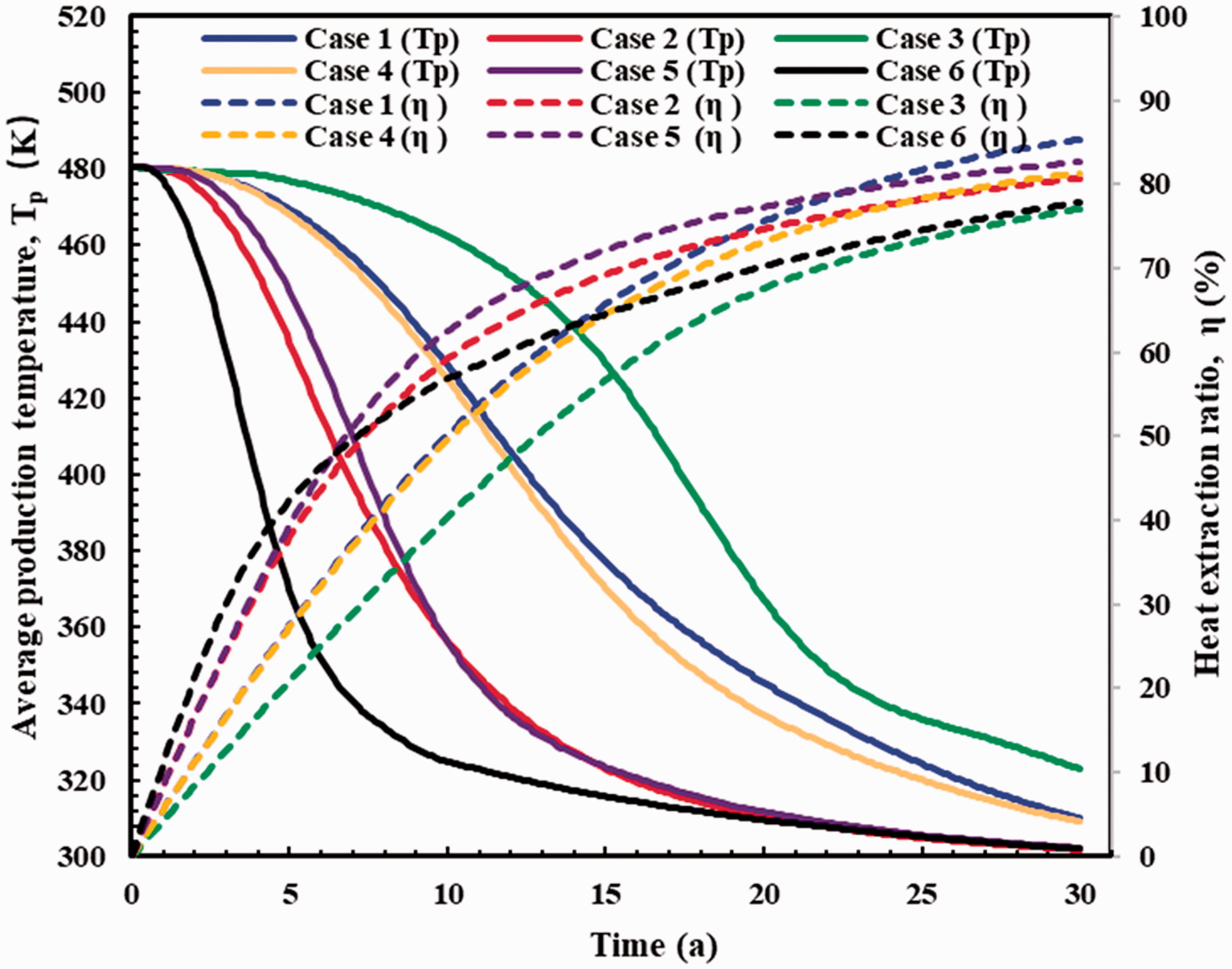
Figure17 demonstrates the average production temperature and life span of different well layout under the total injection mass flow rate of 120 kg/s. From Figure 17 it can be seen that the average production temperature declines with the heat extraction time increases, and the decline trend is different under different well layout. In the first 17 years, the average production temperature of case 3 is higher than other well layout and after the 17th year, and the average production temperature of case 1 is the highest. The average production temperature of case 6 is always the lowest.
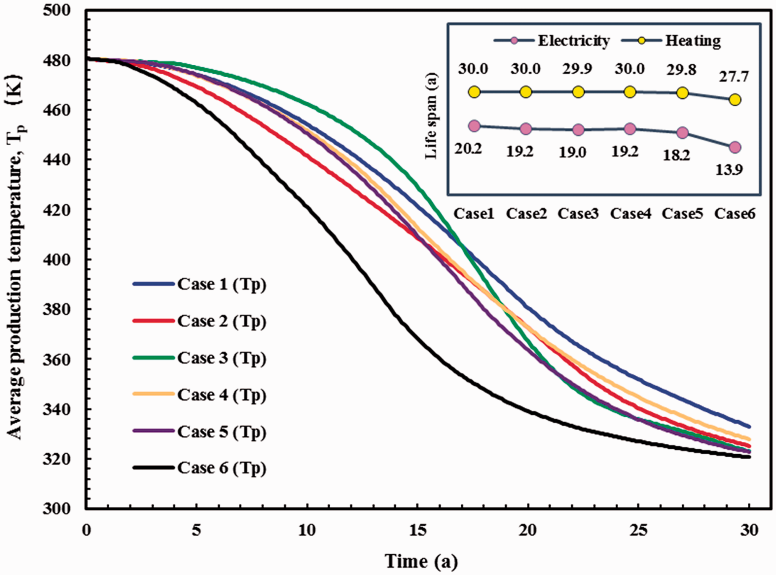
Average production temperature and life span.
For case 2 and case 3, the injection-production well ratio is the same (both are three), and the fracture area of case 2 is larger than that of case 3. In the first 19 years, the average temperature of case 3 is higher than that of case 2 and after the 20th year, the result is contrary. It can be speculated that the production temperature is related to the fracture area when the HDR energy is enough, and the smaller the fracture area, the higher the average production temperature.
For case 3 and case 5, the production well number and fracture area are same, and the injection well number is 3 and 6, respectively. In the first 21 years, the average temperature of case 3 is higher than that of case 5 and after the 22nd year, the average temperature is almost the same. It can be speculated that the production temperature is related to the injection well number when the HDR energy is enough, and the fewer the injection well number, the higher the average production temperature.
In the first few years, the HDR energy is enough, and it is found that the average production temperature is case 3, case 1, case 4, case 5, case 2 and case 6 from high to low, respectively. The injection well number is 3, 4, 4, 6, 6 and 8, respectively. The fracture area is 8.3 × 10⁵, 5.0 × 10⁵, 7.1 × 10⁵, 8.3 × 10⁵, 11.2 × 10⁵ and 12.1 × 10⁵ m2, respectively. From the data above, it can be concluded that the injection well number is the key factor on the average production temperature. When the injection well number is the same, the fracture area plays an important role on the average production temperature. Both the injection well number and fracture area have a negative effect on the average production temperature.
The average production temperature determines the life span of the enhanced geothermal system (EGS). The production temperature should be greater than 378.51 and 323.15 K to meet the electricity generation and heating demand, respectively. For electricity generation, the life span is 20.2, 19.2, 19.0, 19.2, 18.2 and 13.9 years from case 1 to case 6, respectively. For heating demand, the life span is 30.0, 30.0, 29.9, 30.0, 29.8, and 27.7 years case 1 to case 6, respectively. Since the maximum calculation time is 30 years, there may be errors in the life span statics for heating demand.
Average rock temperature and heat extraction ratio
The production mass flow rate is often used as an evaluation criterion in previous studies and it can be calculated by the velocity integral of specific two-dimension region in 3 D model. The calculation result is different with the different integral region. For a certain well layout, we can choose a specific integral region (always the partial fracture region) to calculate the production mass flow rate and use it as an evaluation criterion for sensitivity analysis. However, in this work, the heat extraction of different well layout is mainly compared, there is no identical integral region to choose, and the calculation results of the production mass flow rate with different integral region cannot be put in the same standard for comparison.
Therefore, other characteristic parameters should be found to evaluate the heat extraction process. The average rock temperature is a reliable characteristic parameter. The simulation model is an ideal model and ignores the energy consumption. The lower the average rock temperature, the better is the heat extraction effect, and the heat extraction ratio calculated by the average rock temperature is more accurate. The definition of the heat extraction ratio η is given by
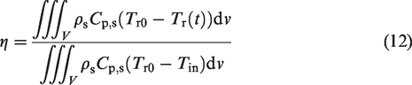
Figure 18 demonstrates the average rock temperature and heat extraction ratio during 30 years of different well layout under the total injection mass flow rate is 120 kg/s. From Figure 18 it is found that the heat extraction ratio is case 3, case 1, case 4, case 5, case2 and case 6 from high to low in the first 25 years, respectively. The results of heat extraction ratio are consistent with the average production temperature.
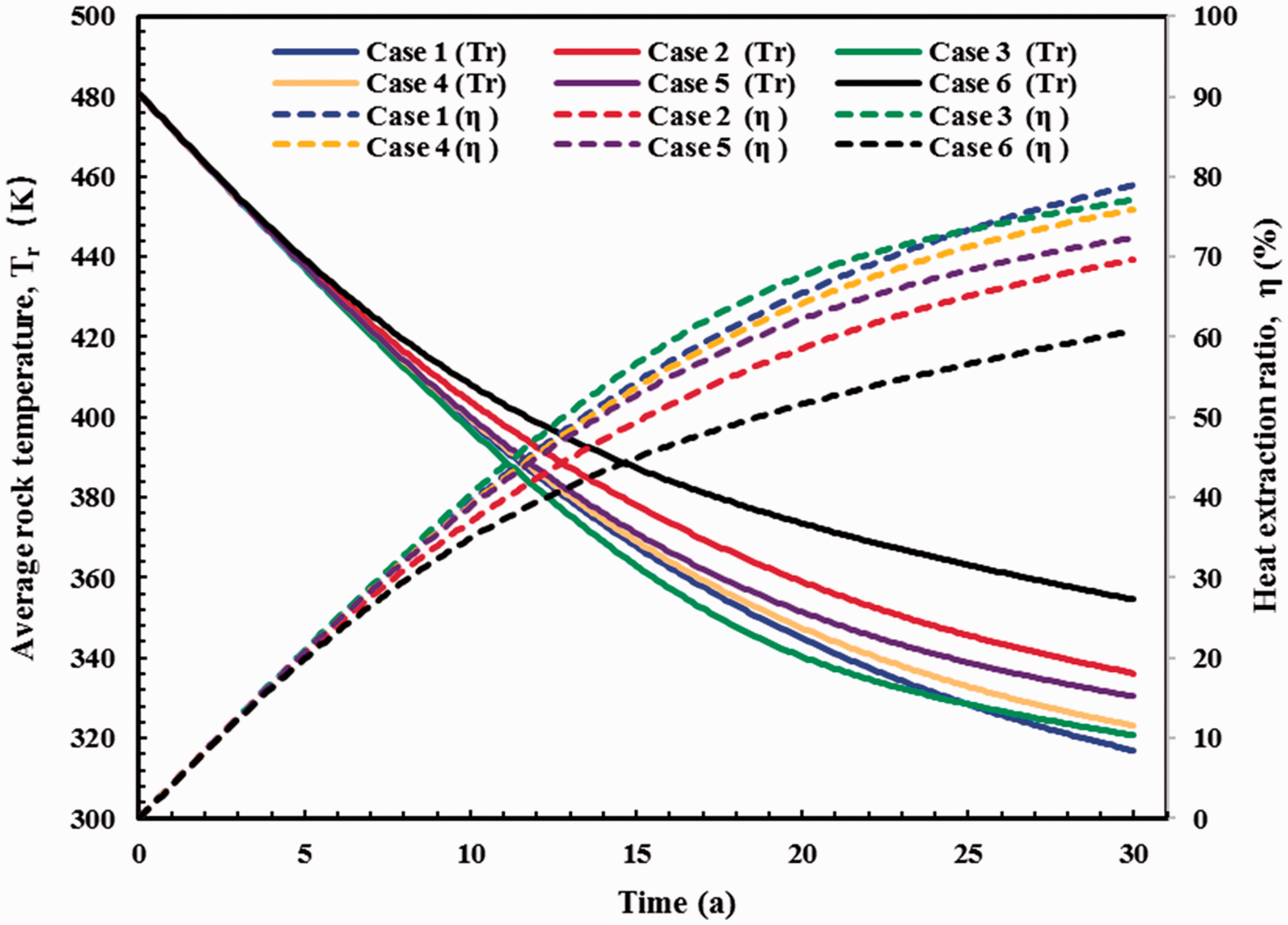
Average rock temperature and heat extraction ratio.
In the last five years, the heat extraction ratio is case 1, case 3, case 4, case 5, case2 and case 6 from high to low, respectively. The fracture area is 5.0 × 10⁵, 8.3 × 10⁵, 7.1 × 10⁵, 8.3 × 10⁵, 11.2 × 10⁵ and 12.1 × 10⁵ m2, respectively. If the simulation time is prolonged to 40 years, the heat extraction ratio of case 4 may surpass that of case 3. Therefore, it can be concluded that the injection well number is the key factor and the fracture area is the secondary factor on heat extraction when the HDR energy is enough, the influence of the injection well number is weakened and the fracture area is the key factor when the HDR energy is not enough.
Figure 19 demonstrates the heat extraction ratio for (a) electricity generation and (b) heating demand of different well layout under the total injection mass flow rate of 120 kg/s. Under the simulation condition, for electricity generation, the heat extraction ratio is 65.83, 57.35, 65.96, 62.79, 59.30 and 43.09% from case 1 to case 6, respectively. For heating demand, the heat extraction ratio is 78.91, 69.63, 77.02, 75.92, 72.27 and 58.94%, respectively. Since the maximum calculation time is 30 years, there may be errors in the heat extraction statics for heating demand. Under the simulation condition, Case 1, Case 3 and Case 4 are the good choice both for electricity generation and heating demand.
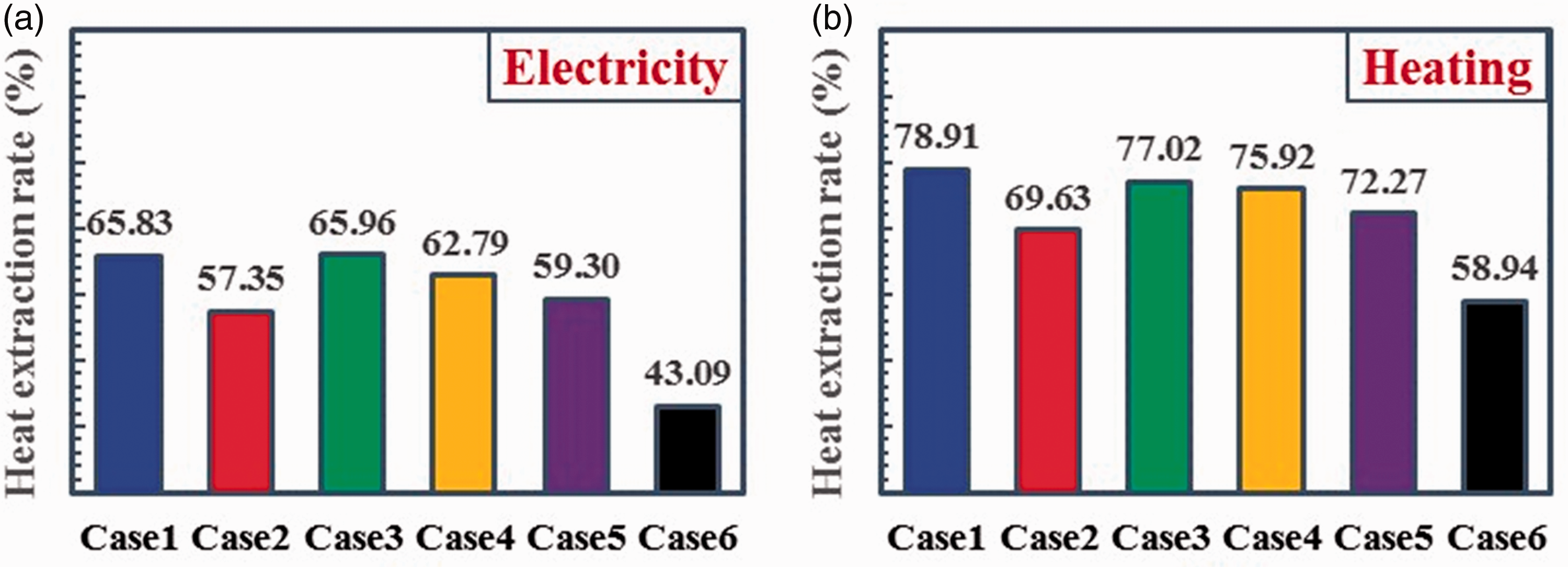
Heat extraction ratio for (a) electricity generation and (b) heating demand.
Effect of injection mass flow rate
The simulation results above are calculated under the total injection mass flow rate of 120 kg/s. In this section, the injection mass flow rate of single well is set as 40 kg/s to compare the heat extraction process of different well layouts.
Figure 20 demonstrates the average production temperature and heat extraction ratio of different well layout under the single well injection mass flow rate of 40 kg/s. From Figure 20 we can see that average production temperature is case 3, case 1, case 4, case 5, case 2 and case 6 from high to low, respectively. The total injection mass flow rate is 120, 160, 160, 180, 180, 320 kg/s, respectively. Under the same single well injection mass flow rate, the total injection mass flow rate depends on the injection well number, the more the injection wells, the lower the average production temperature and the shorter the time to reach a stable temperature. When the injection well number is the same, the fracture area plays an important role on the average production temperature. The larger the fracture area, the lower the average production temperature. The injection well number determines the average production temperature in the whole process.
Average production temperature and heat extraction ratio under the single well injection mass flow rate of 40 kg/s.
Figure 21 demonstrates the heat extraction ratio for (a) electricity generation and (b) heating demand of different well layout under the single well injection mass flow rate of 40 kg/s. Under the simulation condition, for electricity generation, the life span and heat extraction ratio are 14.8, 8.2, 19.0, 14.1, 8.5, 4.6 years and 65.20, 53.40, 65.96, 62.31, 57.64, 40.50% from case 1 to case 6, respectively. For heating demand, the life span and heat extraction ratio are 20.2, 19.2, 19.0, 19.2, 18.2, 13.9 years and 81.90, 69.13, 77.02, 77.28, 72.18 and 58.21%, respectively. Since the maximum calculation time is 30 years, there may be errors in the heat extraction statics for heating demand.
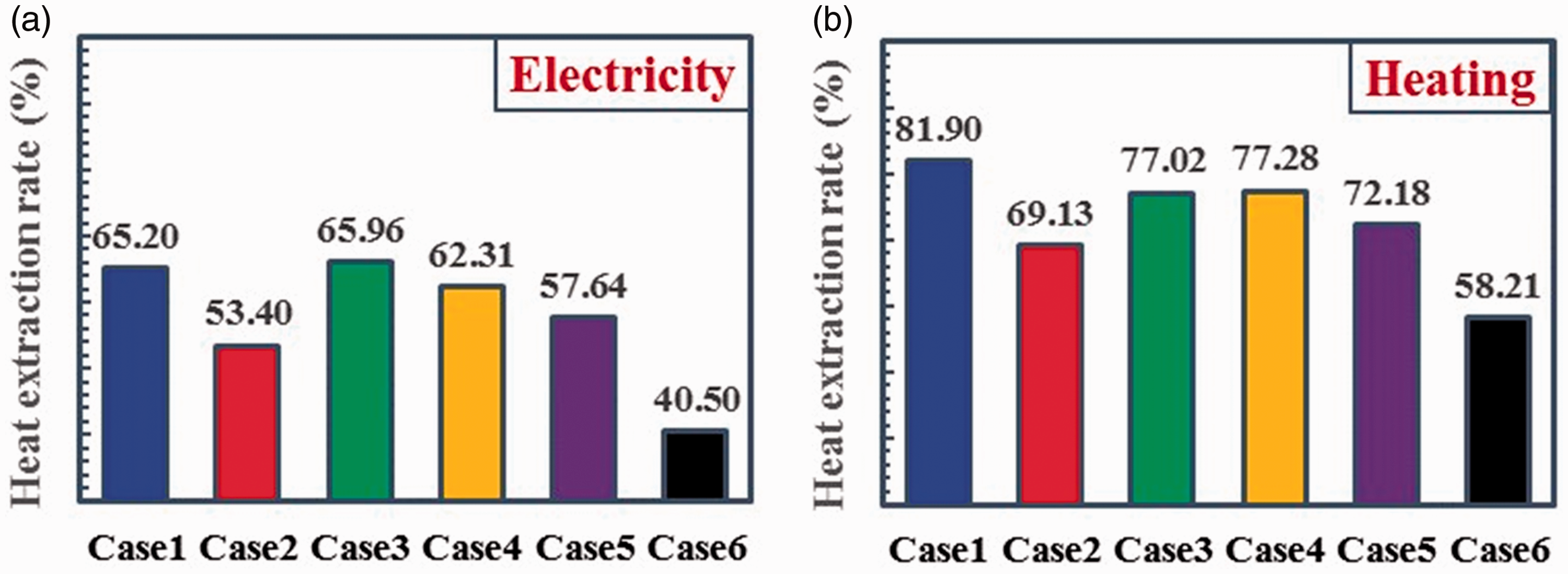
Heat extraction ratio for (a) electricity and (b) heating of different well layout under the single-well injection mass flow rate of 40 kg/s.
From the static results above, it is found that the total injection mass flow rate has negative effect on the life span and heat extraction ratio for the same well layout. Under the simulation condition, Case 1, Case 3 and Case 4 is the good choice both for electricity generation and heating demand.
Effect of injection temperature
Figure 22 compares the average production temperature and heat extraction ratio under the injection temperature of 293.15 and 303.15 K. For case 1, when the injection temperature increases from 293.15 to 303.15 K, the life span for electricity generation is extended from 20.2 to 20.9 years and the heat extraction ratio decreased from 65.82 to 62.79. The same law can be found in case 2 to case 6, too. The higher the injection temperature, the lower the average production temperature and the heat extraction ratio. The low injection temperature is beneficial to the heat extraction for all the cases. The heat extraction ratio of Case1, Case 3 and Case 4 is greatly affected by the injection temperature.
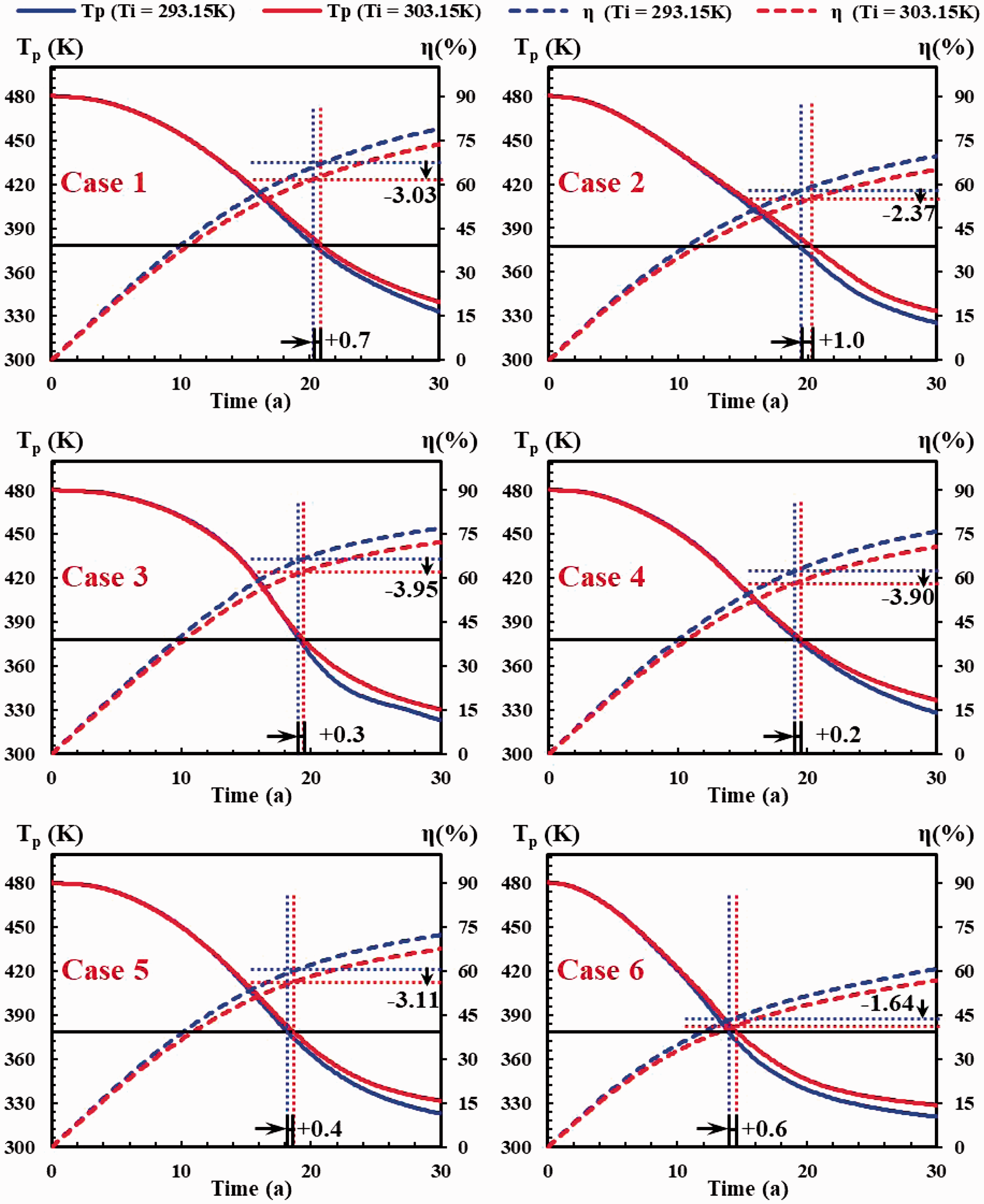
Comparison of average production temperature and heat extraction ratio under the injection temperature is 293.15 K and 303.15 K.
Conclusions
In this paper, six EGS well layout schemes are proposed based on the utilization of abandoned oil–water wells and common oilfield well pattern. Six common injection-production well patterns in oilfield are combined to HDR production and the heat extraction performance is simulated. A thermal-hydraulic model is established to investigate the heat extraction performance of different well layout. Based on the model, the temperature distribution, pressure distribution, average production temperature, life span, average rock temperature and heat extraction ratio are proposed to evaluate the heat extraction performance of different well layout, the heat extraction performance of different well layout is compared, and the effects of injection mass flow rate and injection temperature on the heat extraction performance are studied. In summary, the key points this work are as follows:
Six ideal models for the HDR heat extraction are proposed based on the recovery and utilization of abandoned oil and water wells. The models are row opposite, row cross, four-spot, five-spot, seven-spot and nice-spot well layout from case 1 to case 6, respectively. The vicinity of injection and production well has higher velocity gradient and pressure gradient. The fluid flow velocity mainly depends on the pressure gradient and the thermal residual region is where both the pressure gradient and the fluid flow velocity are small. The injection well number and the location of injection wells have critical influence on the heat extraction performance. It is necessary to choose proper well layout according to actual demand. Under the same total injection mass flow rate, the injection well number is the key factor and the fracture area is the secondary factor on heat extraction when the HDR energy is enough, the influence of the injection well number is weakened and the fracture area is the key factor when the HDR energy is not enough. Both the injection well number and fracture area have a negative effect on the average production temperature. Under the same total injection mass flow rate, Case 1, Case 3 and Case 4 is the good choice both for electricity generation and heating demand. For electricity generation, the life span is 20.2, 19.2, 19.0, 19.2, 18.2 and 13.9 years, and the heat extraction ratio is 65.83, 57.35, 65.96, 62.79, 59.30 and 43.09% from case 1 to case 6, respectively. For heating demand, the life span is 30.0, 30.0, 29.9, 30.0, 29.8, and 27.7 years, and the heat extraction ratio is 78.91, 69.63, 77.02, 75.92, 72.27 and 58.94% from case 1 to case 6, respectively. Under the same single injection mass flow rate, the total injection mass flow rate depends on the injection well number, and the more the injection wells, the lower the average production temperature and the shorter the time to reach a stable temperature. Under the same single well injection mass flow rate, Case 1, Case 3 and Case 4 are the good choice both for electricity generation and heating demand. Under the same total injection mass flow rate, the higher the injection temperature, the lower the average production temperature and the heat extraction ratio. The heat extraction ratio of Case1, Case 3 and Case 4 is greatly affected by the injection temperature.
However, the hydraulic-mechanical couple is not taken into consideration in this paper, and the heat extraction performance of six EGS well layouts needs further study in the future.
Supplemental Material
EEA880350 Supplemental Material1 - Supplemental material for Numerical simulation on heat extraction performance of enhanced geothermal system under the different well layout
Supplemental material, EEA880350 Supplemental Material1 for Numerical simulation on heat extraction performance of enhanced geothermal system under the different well layout by Yuanyuan Ma, Shibin Li, Ligang Zhang, Hao Li and Zhaoyi Liu in Energy Exploration & Exploitation
Supplemental Material
EEA880350 Supplemental Material2 - Supplemental material for Numerical simulation on heat extraction performance of enhanced geothermal system under the different well layout
Supplemental material, EEA880350 Supplemental Material2 for Numerical simulation on heat extraction performance of enhanced geothermal system under the different well layout by Yuanyuan Ma, Shibin Li, Ligang Zhang, Hao Li and Zhaoyi Liu in Energy Exploration & Exploitation
Footnotes
Acknowledgement
The authors wish to thank Prof Shibin Li.
Declaration of conflicting interests
The author(s) declared no potential conflicts of interest with respect to the research, authorship, and/or publication of this article.
Funding
The author(s) disclosed receipt of the following financial support for the research, authorship, and/or publication of this article: This study is supported by the National Natural Science Foundation of China (Grant No. 51874098).
References
Supplementary Material
Please find the following supplemental material available below.
For Open Access articles published under a Creative Commons License, all supplemental material carries the same license as the article it is associated with.
For non-Open Access articles published, all supplemental material carries a non-exclusive license, and permission requests for re-use of supplemental material or any part of supplemental material shall be sent directly to the copyright owner as specified in the copyright notice associated with the article.