
Abstract
In this study, the operation of a ground source heat pump system was investigated over a 25-year period with careful attention paid to the effects of groundwater flow and intermittent operation strategies. First, geological and hydrogeological investigations were conducted, after which ground thermal properties were determined by thermal response tests. In order to predict the heat transfer within borehole heat exchangers under a specific operating system, a numerical model was developed using finite element subsurface flow & transport simulation system (FEFLOW). The numerical model was validated with thermal response test measurements. Three operation conditions including continuous system operation without groundwater flow, continuous system operation with groundwater flow, and intermittent operation with groundwater flow were examined. Results indicate that ground temperature disturbance was effectively reduced during groundwater flow and the intermittent operation of the system. Compared with continuous system operation without groundwater flow, the borehole heat exchanger heat transfer rate increases by 10% with groundwater flow conditions and increases by 16% with further implementation of the intermittent operation strategy. Intermittent operation with groundwater flow is highly recommended for the sustainable operation of ground source heat pump system.
Keywords
Introduction
Ground source heat pump (GSHP) systems have been rapidly developed as highly efficient energy technology for the heating and cooling of buildings in the past few decades (Blum et al., 2010). In general, GSHP systems mainly consist of three parts: (1) the borehole heat exchangers (BHEs), (2) the heat pump system, and (3) the indoor units. Heat is extracted/rejected from/to the ground via the BHE (Cui et al., 2006), allowing GSHP systems to achieve higher energy efficiency as compared with traditional air-conditioning systems (Florides and Kalogirou, 2007). However, performance may decline after long-term operation due to disequilibrium effects between cooling and heating loads in the winter and summer in many regions (Zhu et al., 2015). Several studies have focused on how groundwater flow influences the ground temperature, especially in relation to the operation of GSHP systems. Heat advection with groundwater flow provides additional heat sinks (i.e., if the BHE rejects heat) or heat sources (i.e., if the BHE extracts heat), leading to enhanced performance (i.e., less extreme temperatures) and steady state (Banks, 2014). Groundwater flow can exert an obvious influence on first-dimensional temperature fields (Diao et al., 2004), and groundwater flow noticeably lessens cooling–heating enrichment as a result of the long-term operation of GSHP systems (Zanchini et al., 2012). Furthermore, groundwater flow increases the heat transfer rate of buried pipes (Luo et al., 2015).
For effects related to intermittent system operation, previous studies have shown that intermittent heating can increase the heat transfer rate of buried pipes (Chen et al., 2011), as well as significantly relieving heat accumulation in soil (Shang et al., 2011; Yang et al., 2014).
Both groundwater flow and intermittent operation have the ability to increase buried pipe heat exchange efficiency, but previous studies failed to consider the effects of these two factors on the efficiency of GSHP operation. This study focuses on a GSHP system in Zhangqiu City, Shandong Province, by using heat–mass transfer theories in porous media to establish a moisture–heat coupling numerical model that observes ground heat exchanges in the aquifer. We also predict the temperature evolution during the course of system operation and analyze how groundwater flow and intermittent operation affect the GSHP’s efficiency.
Study principle and method
Moisture–heat coupling numerical model
Heat transfer through a porous medium is composed of heat conduction in the solid phase and the stagnant liquid and heat advection through the liquid phase. By applying the law of energy conservation to a control volume, the equation that governs coupled heat and flow transfer is written as follows (Diersch et al., 2010; Long et al., 2015; Luo et al., 2013)

The governing equation describes one-dimensional discrete element flow following Darcy’s law, which can be expressed as (Xue and Xie, 2007)
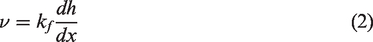
For heterogeneous anisotropic media, the mass conservation relation of groundwater movement is detailed as follows, i.e., the aquifer water level h in equation (2) is used to find the solution (Xue and Xie, 2007)

The heat transfer model (equation (1)) and water flow model (equation (3)) are coupled via the Darcy velocity, v (equation (2)), but we neglect natural convection, caused by different water densities, and the thermodynamic equilibrium of groundwater and underground media skeleton is supposed to be completed instantly (Yu et al., 2015).
Solution
FEFLOW software is applied in this study to solve the moisture–heat coupling model. FEFLOW, which was developed in 1979 by Germany’s Danish Hydraulic Institute, is considered to be one of the best computer software system for simulating groundwater quantity, heat transfer, and mass transfer. This software provides a good description of the geological conditions and can simulate the heat transfer rate of BHEs under complicated hydrogeological conditions. For the inside part of the borehole, a quasi-stable analysis model is applied and a finite-element model simulates the outside of the borehole, thus providing a coupled model between the analysis and numerical models. This method still consumes significant time and computational resources, but several problems, associated with traditional numerical simulations such as large number of grids and long simulation periods, are avoidable to a certain extent (Zhao et al., 2016).
Project example
Site introduction
The GSHP project is located in Zhangqiu, Shandong Province, with a total area of 353 m2. The test site has 12 BHEs laid out in a 4 × 3 pattern, with a borehole spacing distance of 3.5 m × 3.5 m (Figure 1). All bores have a diameter of 150 mm and a depth of 100 m.
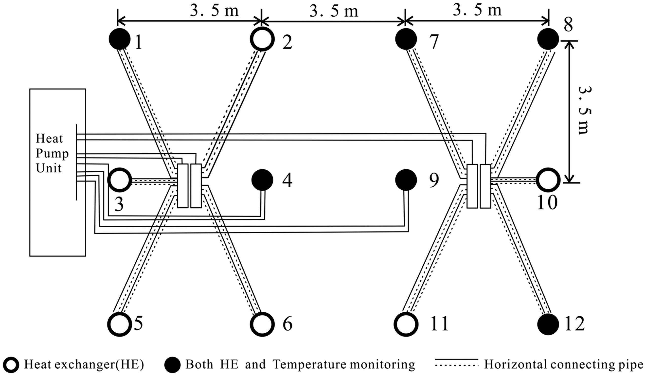
Layout of the borehole heat exchangers.
Geological conditions
The study site is located within a transitional area between low hills and a piedmont plain and can be defined as a piedmont sloping plain. Located to the east, there is a small monadnock denudation area, where the terrain is elevated in the east and lowers in the west. With an altitude of 108–113 m, the landform is characterized by denudation landform. The lithology mainly includes sandstone, mudstone, silty mudstone, fine sandstone, silty fine sandstone, and pelitic siltstone. According to the hydrogeological investigation, the groundwater depth is 34 m and flows southeastward. Groundwater is mainly composed of clasolite fracture water with a hydrochemical type of SO4·CO3–Ca.
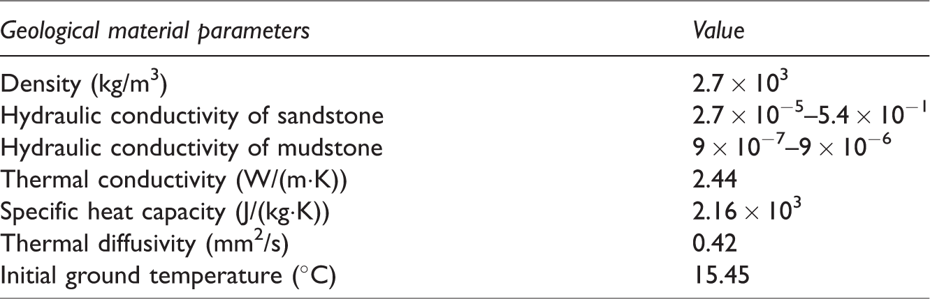
According to in situ thermal response test (TRT) and laboratory measurement, the effective thermal conductivity is 2.44 W/(m·K), the specific heat capacity is 2.16 × 10³ J/(kg·K), the thermal diffusivity is 0.42 mm2/s, and the original ground temperature is 15.45°C. According to in situ measurements, the hydraulic gradient is 1.34 × 10⁻³. Hydraulic conductivity of sandstone and mudstone are set as empirical value according to Zheng and Bennett (1995). The average groundwater velocity was calculated based on the hydraulic gradient and hydraulic conductivity. The specific calculation process is as follows: the initial water table depth distribution is obtained by interpolating the measured borehole water table depth among the simulation area. Darcy flow equation was applied to get the instantaneous water table depth at each point (equation (3)). After that the hydraulic gradient and the groundwater velocity can be easily got using equation (2). Table 1 shows the main parameters used in this study.
Thermal and physical properties of the geological materials.
Numerical simulations
Model development
The construction of the GSHP numerical model depends on the onsite geological conditions and project overview. Figure 2 illustrates a schematic diagram of the three-dimensional model. The model, whose size is 100 m × 100 m × 110 m, is divisible into three geological units: (1) sandstone at depths between 0 and 11.4 m, (2) mudstone at depths between 11.4 and 34 m, and (3) sandstone imbedded with mudstone at depths between 34 and 110 m. Grid refinement occurs near the BHE, and refinement precision is more than six points according to FEFLOW’s requirements to ensure result stability. The temperature of outlet fluid and the temperature of ground surface as well as 34 m depth, 50 m depth, and 100 m depth were recorded.
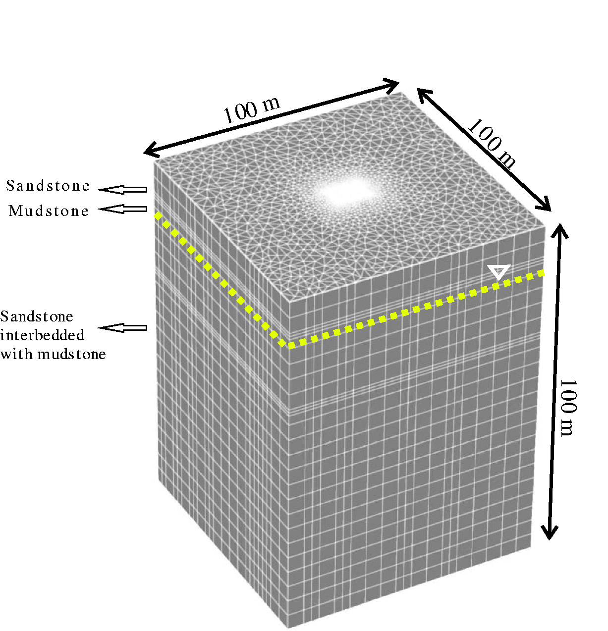
Three-dimensional overview of the numerical model and its discretization.
The model’s boundary conditions are as follows: the upper reach of the field contains one type of water head boundary condition and one type of heat boundary condition (Dirichlet condition), but no boundary conditions exist in the lower reach of the field, such that fluid and heat have free outflow. The parallel flow field boundary is defined as a non-flow boundary condition. The BHE is defined as the well flow boundary according to FEFLOW, which is a Type IV boundary condition. To prevent boundary effects, we place the model boundary at 50 m away from the BHE.
Model correction
The outlet fluid temperature simulated by the FEFLOW software is compared with the observed data of TRT with the actual double U-tube. After longtime variation, the difference between these two methods is small. Figure 3 shows the correction results, and we observe that the observed and simulated outlet fluid temperatures are almost identical. The square root error between the two sets of data is less than 0.1°C, which indicates that the model’s precision is within the onsite measurement precision (Wang et al., 2016) as well as that the underground heat transfer model is reasonable and able to predict the operation of the actual system.
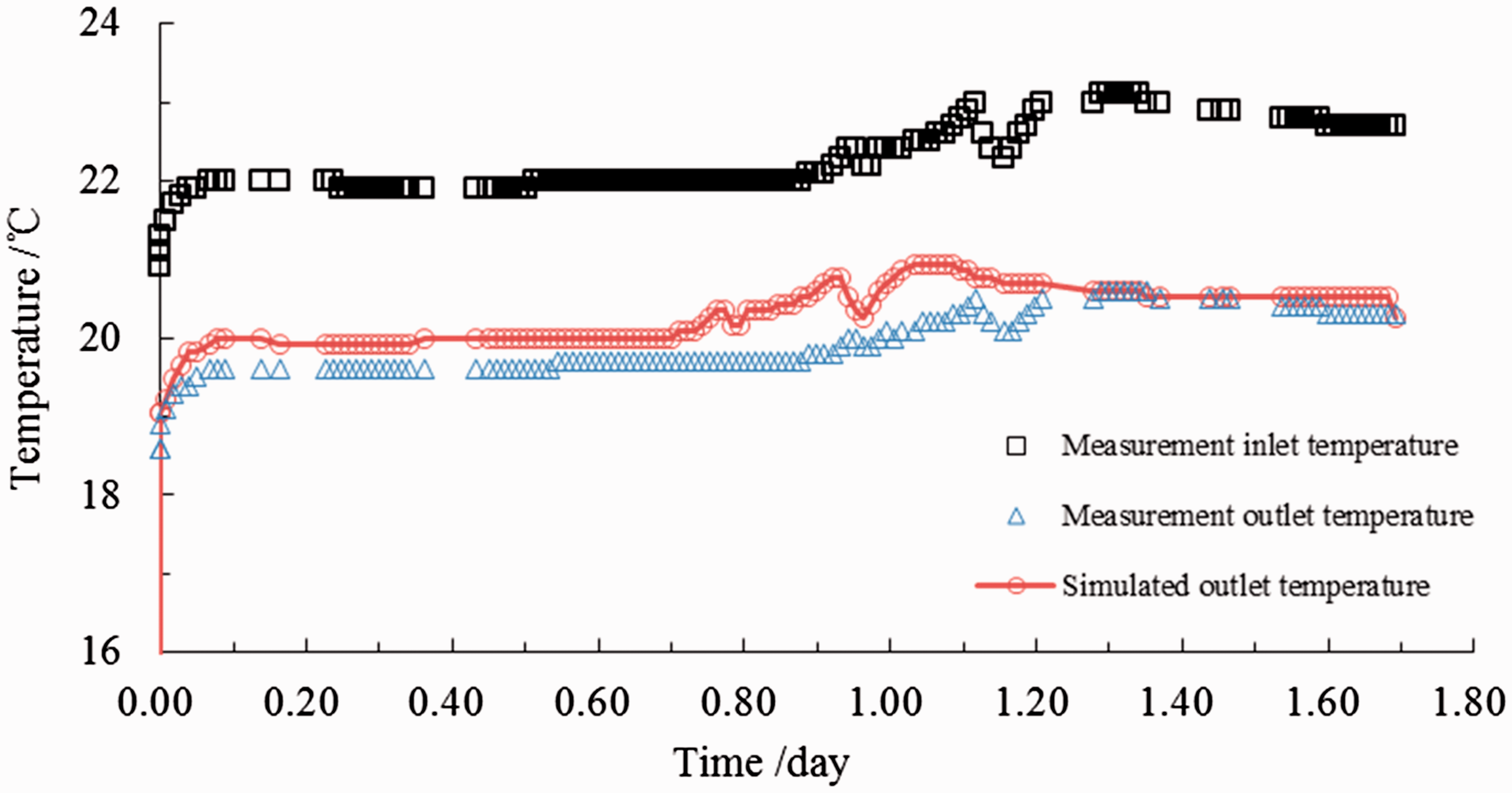
Comparison of simulation results with measurements from the double U-tube model for validation.
Model working conditions
In order to provide the scientific system design and operation management suggestions, both groundwater flow and intermittent operation were considered in this paper. Numerical simulations for three working conditions were performed: (1) continuous system operation without groundwater flow, (2) continuous system operation with groundwater flow, and (3) intermittent operation with groundwater flow. Cooling and heating loads were equally distributed to each BHE by taking into account building energy consumption and the local average performance of the GSHP. The intermittent operation of the system is set up according to energy demand characteristics for local buildings. Heating periods extend from November to March, while cooling periods extend from June to September, although the system remains idle during other periods. Loads are designed according to local temperature and borehole load characteristics. Figure 4 shows the distribution of monthly loads during a one-year period.
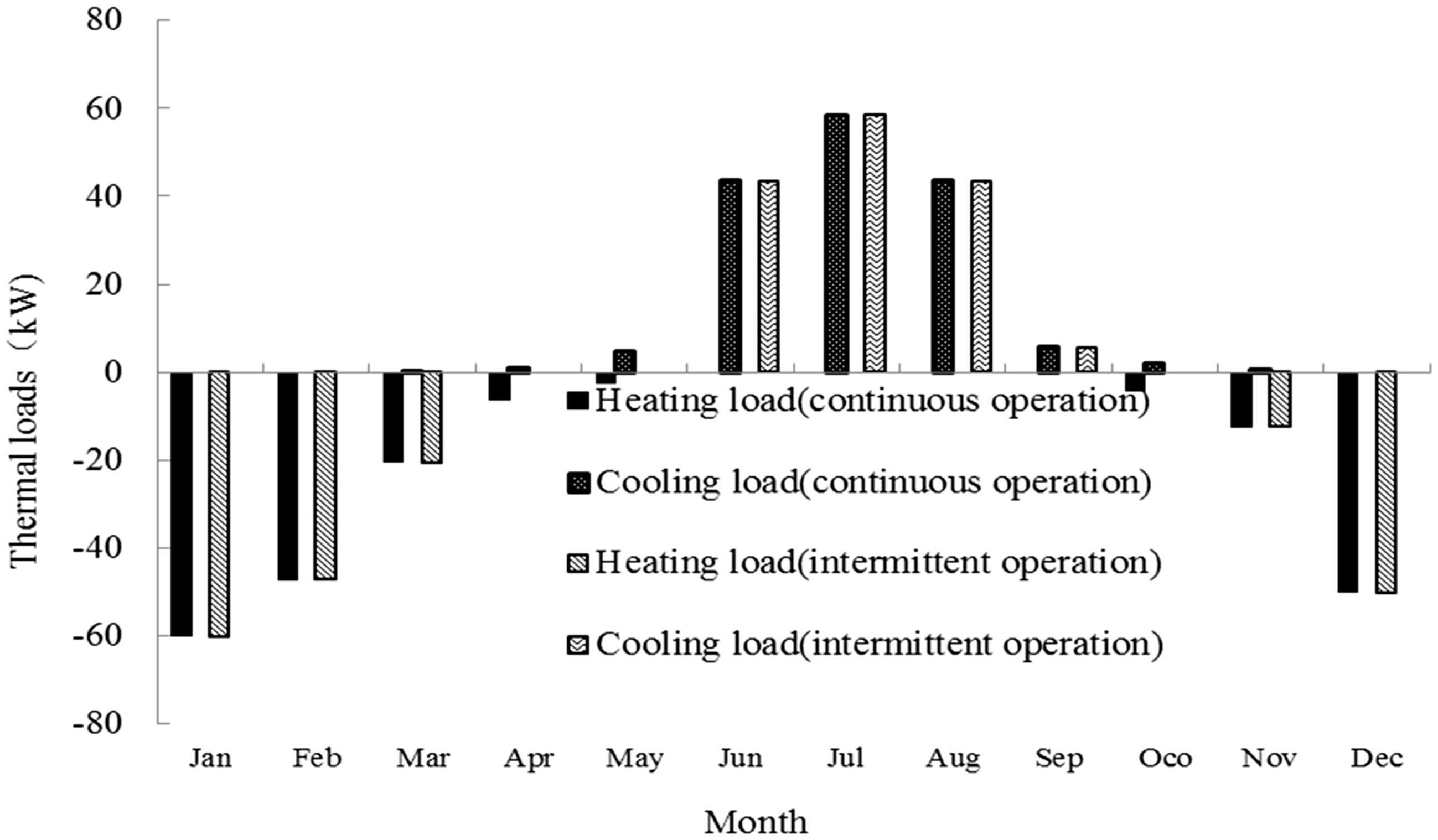
Power input and output under continuous and intermittent operation during a one-year period.
Results and discussions
Characteristics during continuous operation without groundwater flow
The design of simulated operation condition is considered according to the TRT data and the water inlet fluid temperature is set as 22°C in the summer and 6°C in the winter. After a decade-long operation, the outlet fluid temperature at different depths has slightly different temperatures. The outlet fluid temperature was as low as 20.65°C in the summer and as high as 7.35°C in the winter. After operation for 25 years, the outlet fluid temperature was as low as 20.99°C in the summer, implying an increase of 0.34°C compared with the temperature after decade-long operation. The outlet fluid temperature was as high as 6.85°C in the winter, implying a decrease of 0.5°C compared with the temperature after decade-long operation. This indicates that longer operation periods reduce the energy efficiency of the GSHP.
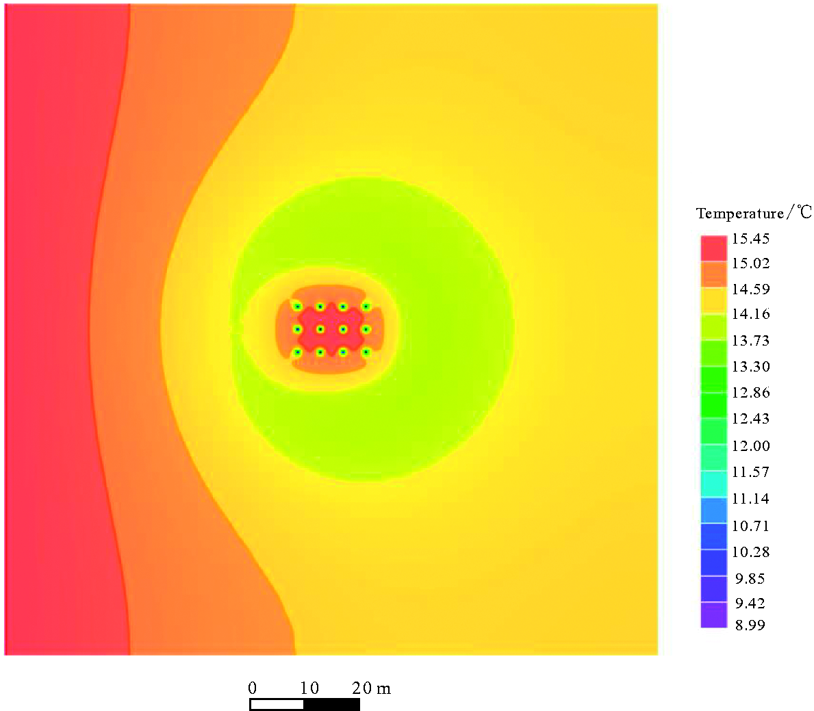
As heat exchange continues, the scope of the influence of temperature continuously expands, and ground temperature distributions gradually change from circular to outward radiation. Figure 5 indicates that the temperature at the center of the buried pipes in summer is approximately 15.5°C, falling and then rising from the center to the surroundings. If we define the effects on the ground with a temperature change of 0.1°C (Deng, 2015), the ground radius of influence is approximately 33 m in the summer and 66 m in the winter after operation for 25 years.
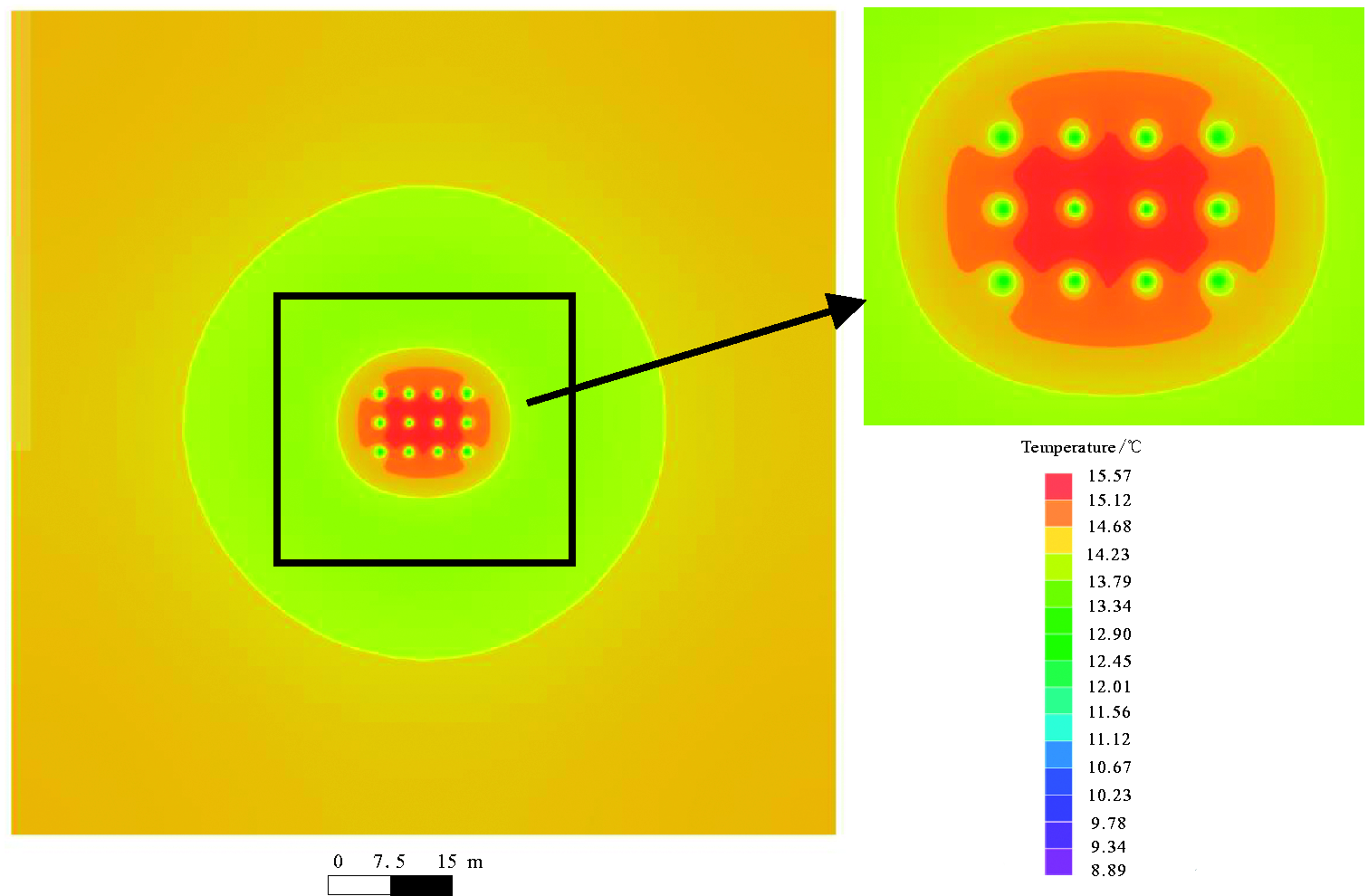
Ground temperature distribution after 25 years of operation (in winter).
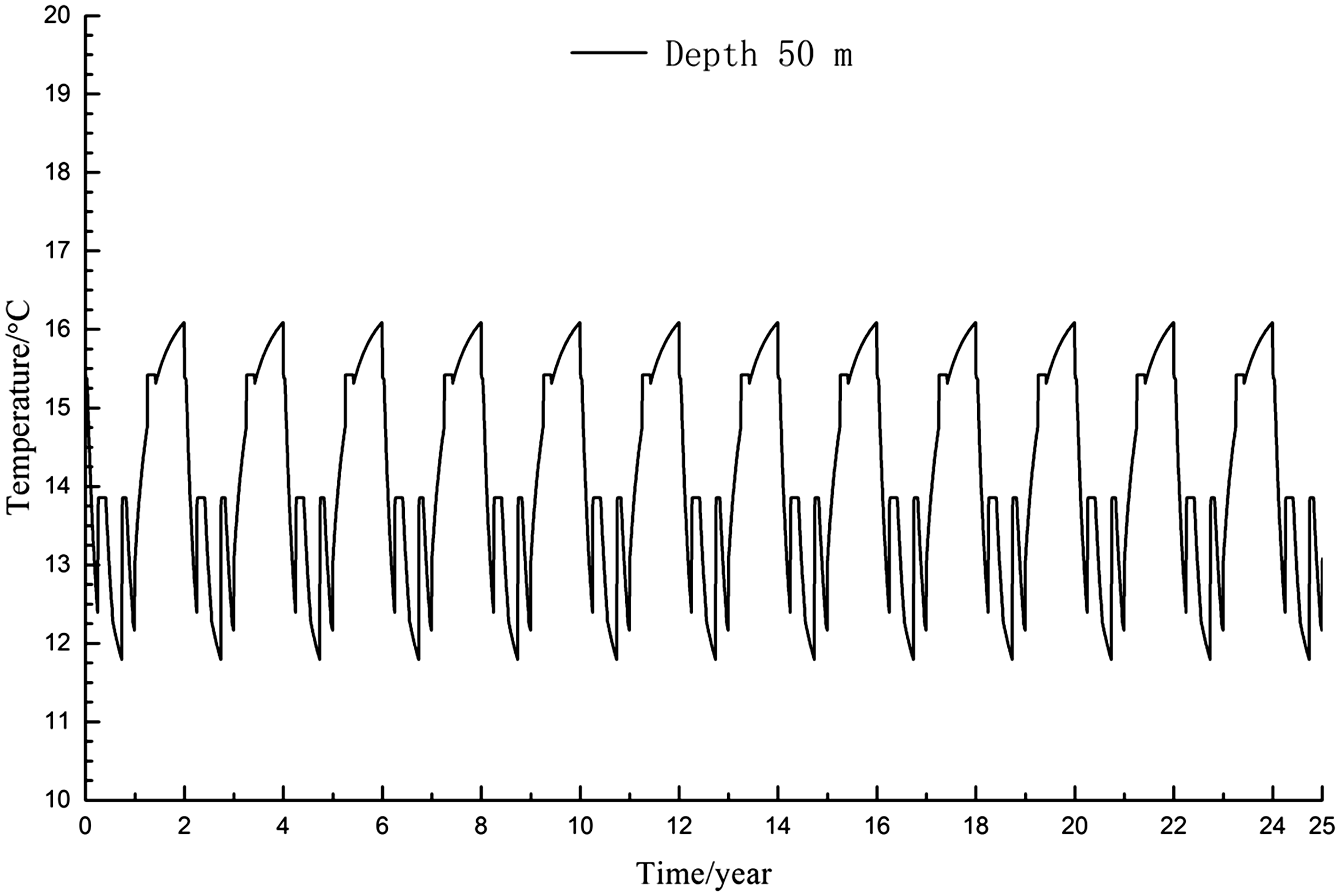
When we analyze the changes in ground temperature over the 25-year period, we use a burial depth of 50 m (Figure 6) as a hypothetical example to observe whether changes in ground temperature at different depths share similar trends. With the system’s continuous operation, however, the difference between the highest and lowest temperature gradually increases. After GSHP continual operation for 25 years without groundwater flow, the maximum temperature difference is 6.28°C. The accumulation of transferred heat occurs due to uneven distribution of cooling and heating loads during GSHP operation. The ground temperature surrounding the heat exchanger continues to decline for years. The onsite monitoring data indicate that, in this GSHP scenario, the heat transfer rate for BHE is 47.22 W/m in the winter and 26.22 W/m in the summer.
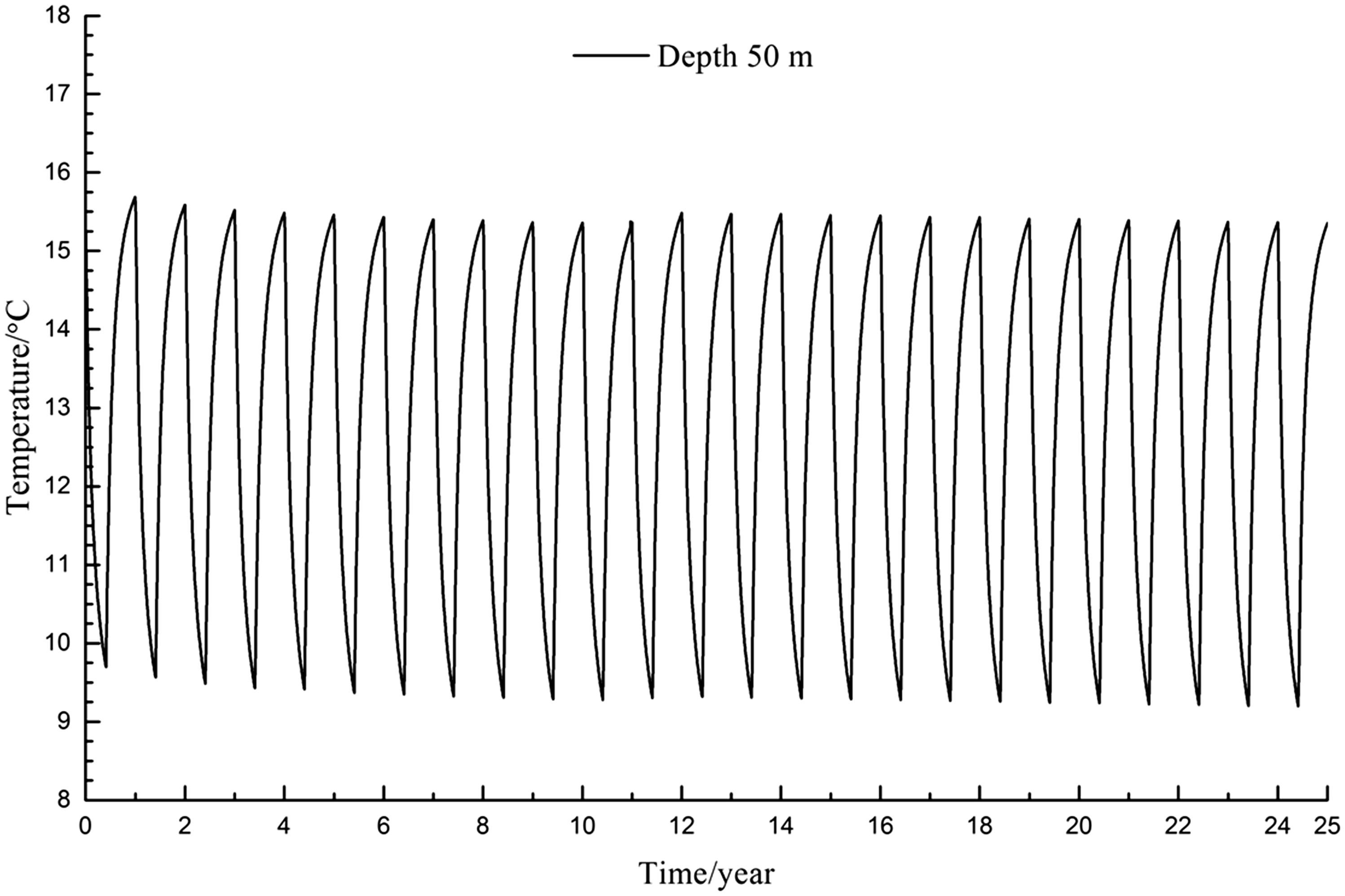
Ground temperature variations at a depth of 50 m during 25 years of continuous operation without groundwater flow.
Characteristics of continuous operation with groundwater flow
We initiate the model with groundwater flow according to the site’s hydrogeological conditions. The hydraulic gradient is set as 1.34 × 10⁻³ based on the groundwater table depth and the hydraulic conductivity, and the double U-shaped buried pipe flow rate is set as 1.56 L/s according to the average flow rate during the TRT. Under this working condition, the outlet fluid temperature was as low as 0.41°C in the summer and as high as 7.84°C in the winter after a 25-year operation period. The outlet fluid temperature only has little change, and the heat exchange system remains stable during the 25-year period.
Figure 7 shows the ground temperature distribution nephogram under the influence of the groundwater system after a 25-year period of GSHP operation. As indicated in Figure 7, we observe that heat exchange processes gradually experience an outward, “circular” radiation, whose direction is towards the lower reaches of groundwater flow. Ground temperature in the lower reaches is around 1°C lower than that of the upper reaches. Vertically, the influence of temperature decreases with increasing the depth. If we define the effects on the ground with a temperature change of 0.1°C (Deng, 2015), the ground radius of influence is approximately 25 m in the summer and 53 m in the winter after operation for 25 years. These results suggest that the mutual coupling of temperature and hydraulic gradients, in the presence of groundwater flow, influences the heat exchange between buried pipes and the surrounding ground. This form of heat transfer includes heat conductivity, heat convection, and heat dispersion which strengthen the fluid heat transfer such that the affected radius significantly decreases (Shao et al., 2016).
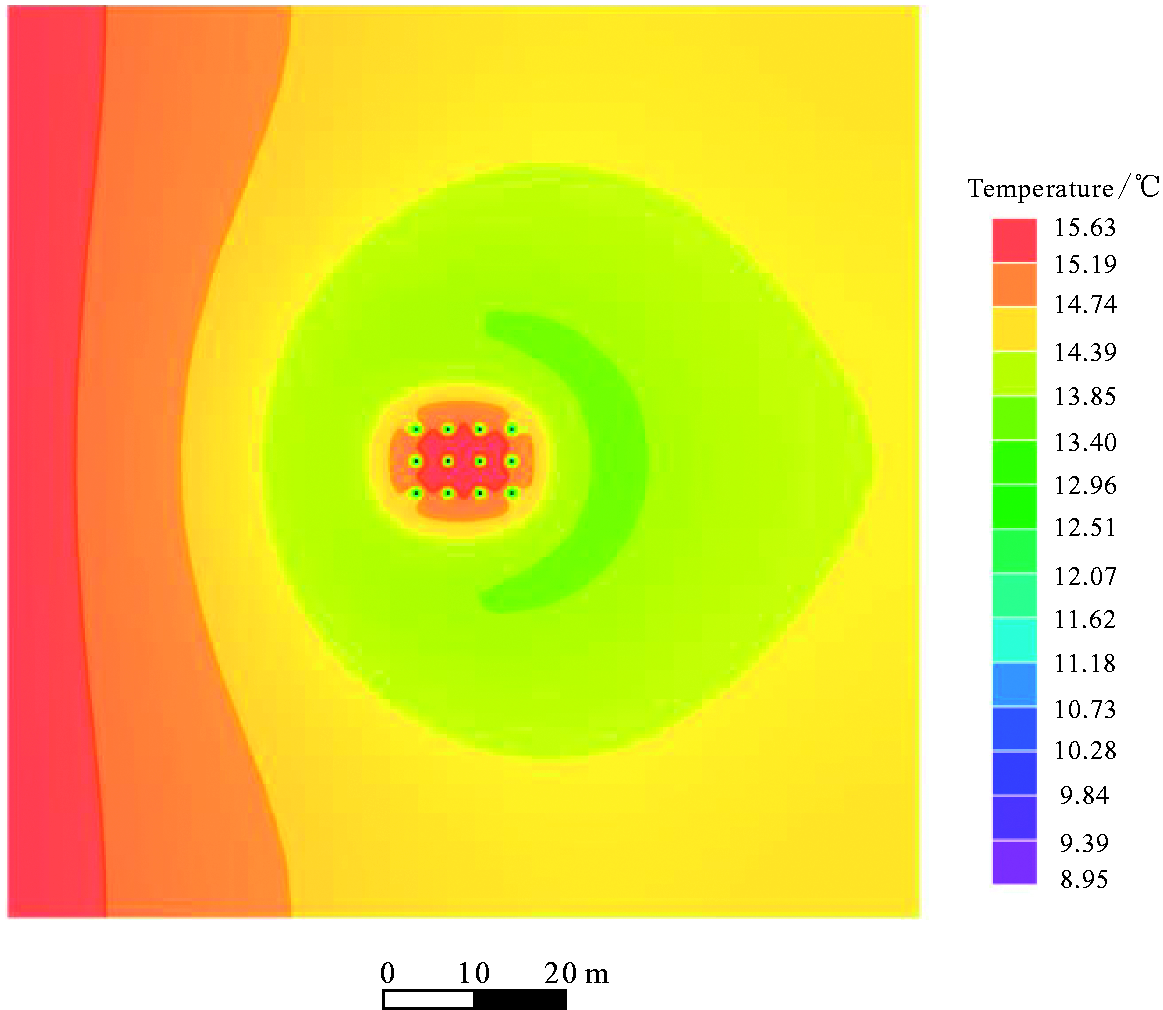
Ground temperature distribution after 25 years of operation with groundwater flow (in winter).
Changes in ground temperature after GSHP continuous operation for 25 years in the presence of groundwater flow shows that temperature gradually decreases, and the difference between the highest and lowest temperature slightly widens. Compared with the scenario without groundwater flow, the temperature difference becomes smaller and is only 5.40°C. The cold accumulation phenomenon has been effectively mitigated due to heat convection and heat dispersion caused by the groundwater flow (Zhu et al., 2013). Calculation results show that the heat transfer rate is 51.94 W/m in the winter and 31.20 W/m in the summer.
If we compare the working condition with without groundwater flow, our results indicate that the thermal influence radius decreases by 13 m and the lowest ground temperature rises from 9.0°C to 9.7°C. In the early stages of system operation, the heat transfer rate vary little whether groundwater flow is available or not, but the rate becomes larger compared with the absence of groundwater flow as the long-term operation.
Characteristics of intermittent operation with groundwater flow
The cold and heat accumulation phenomenon originates from the continuous operation of the GSHP for long periods. As a negative operation model, this leads to a noticeable decrease in the GSHP’s heat transfer rate. To guarantee long-term operation, intermittent operation should be taken into account. The heating period is from November to March, and the cooling period is from June to September. The system remains idle during other periods. The ground temperature distribution during intermittent operation is much more balanced (Figure 8). The tendency of temperature distribution is quite similar to the continuous operation scenario, but the lowest ground temperature rises by 0.5°C. The cold accumulation phenomenon improves to a certain degree, whereas ground temperature in winter is approximately 0.4°C higher compared with the continuous operation scenario. The largest temperature difference under cooling and heating conditions is 4.9°C (Figure 9). The analysis and calculation of temperature changes for the inlet and outlet fluid show that the heat transfer rate for the heat exchange pipes is 32.45 W/m in the summer and 54.54 W/m in the winter.
Ground temperature distribution after 25 years of intermittent operation with groundwater flow (in winter).
Ground temperature variation at a depth of 50 m during 25 years of intermittent operation with groundwater flow.
Comparison of the three schemes
Based on the energy generated during days of cooling and heating associated with the annual operation of the GSHP, heat transfer rate of BHE during the three working conditions, for each linear meter, is listed in Table 2. The heat transfer rate increases by approximately 10% when continuous operation with groundwater flow is compared with without groundwater flow, and the heat transfer rate increases by approximately 16% when intermittent working condition with groundwater flow is compared with the continuous working condition without groundwater.
BHE heat transfer rate under different operating conditions.
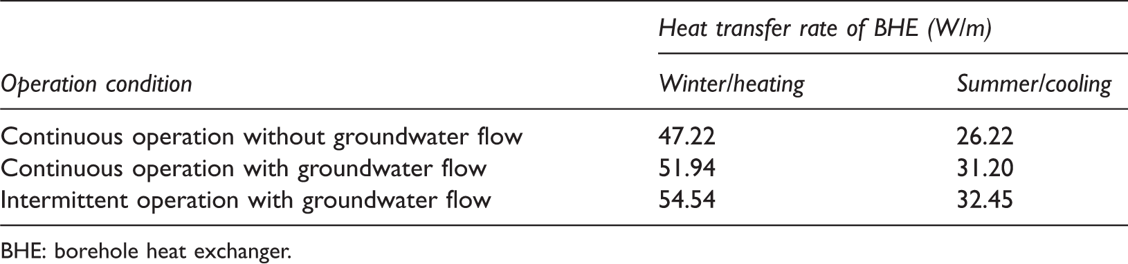
BHE: borehole heat exchanger.
Conclusions
This study created a site-specific hydrogeological and heat transfer model and analyzed the ground temperature distribution and heat transfer rate after system operation for 25 years under three operation scenarios including continuous system operation without groundwater flow, continuous system operation with groundwater flow, and intermittent operation with groundwater flow. These conditions were used in conjunction with a survey and study of a GSHP system in Zhangqiu, Shandong Province. The main conclusions are as follows:
Numerical simulations were used to obtain the underground temperature distribution during GSHP system operation under three working conditions. In the first scheme of continuous operation without groundwater flow, the maximum ground temperature difference under cooling and heating conditions is 6.28°C. In the second scheme of continuous operation with groundwater flow, the maximum ground temperature difference is 5.4°C. Finally, in the third scheme of intermittent operation with groundwater flow, the maximum temperature difference is 4.9°C. A comparison of the three working conditions reveals that ground temperature disturbance was effectively reduced during groundwater flow and the intermittent operation of the system which reduces ground temperature difference and relieves cold and heat accumulation of the ground.
Heat transfer rate under three working conditions was analyzed . Compared with continuous system operation without groundwater flow, the BHE heat transfer rate increases by 10% with groundwater flow conditions and increases by 16% with further implementation of the intermittent operation strategy. This proves that both groundwater flow and intermittent operation increase the system’s heat transfer rate. The effects of these two factors should be taken into consideration during system design and operation management to increase the system’s overall energy efficiency.
Footnotes
Declaration of conflicting interests
The author(s) declared no potential conflicts of interest with respect to the research, authorship, and/or publication of this article.
Funding
The author(s) disclosed receipt of the following financial support for the research, authorship, and/or publication of this article: This work was supported by the National Key R&D Program of China (No. 2018YFC0604306), National Natural Science Foundation of China (No. 41302189 and No. 41672249) and Chinese Academy of Geological Sciences Hydrogeological Environment Geology Institute Foundation (No. SK201501).