
Abstract
This paper presents the simulation-based development of a novel knitted design of textile heating structures based on dedicated serial-parallel circuits for heating (DSPCh) using silver-plated yarns processed via knitting technology. The DSPCh approach features dedicated and spatially bounded sub-circuits, ensuring even heat distribution and resilience against circuit failures in smart textiles with heating functionality. The study finds that the conductor arrangement and knitting pattern significantly affect the heating performance. DSPCh structures achieve even more heat distribution than serial and parallel circuit designs. Due to its binding, the developed basic pattern based on the right–left knit is less electrically conductive than that based on the right–right knit.
Results show that DSPCh structures exhibit a favorable heat level and uniform heat distribution suitable for wearable textiles close to the body. The comparison with other circuit designs demonstrates higher temperatures of maximum 132°C and temperature differences up to 100 K, making DSPCh structures suitable for functional underwear. In addition, the experiments reveal that the heating performance is minimally degraded after standard machine-washing and care protocols. The investigations demonstrate that the DSPCh structures are suitable for actively heatable functional underwear, and simulation tools can aid in predicting temperatures and heat distribution for various textile designs.
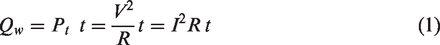
The market for clothing with integrated intelligent functions is steadily increasing. 1 Smart textiles (STs) combine textiles with electronic components. 2 STs include textiles for medicine and healthcare applications, 3 for example, for biomonitoring of physiological parameters, 4 active warming garments (AWGs) 5 and many more. In AWGs, the basic principle is the conversion of electrical energy into heat. When a current flows through a resistor it generates thermal energy Qw according to Joule's first law. 6
If the current I flows through a conductor with a resistance R driven by a constant voltage V the conductor converts the electrical power P, which is determined by using Equation (1):
The development of AWGs is a diverse and forward-looking field of research because such clothing can increase well-being and minimize health hazards due to freezing of extremities at cold-exposed workplaces. 7 The combination of flexible textiles for the production of AWGs and the often rigid electronic components, in this case, the electrically conductive heating structures, create various challenges in developing AWGs. 8 Users pose several requirements for the comfort and function of AWGs that imply the combination of materials with different physical properties. 9 Silver-plated yarns (SYs) are coming into focus for the development of STs, because of their flexibility and processability in textile processes and their electrically conductive properties. 8 Due to their skin-friendliness and antimicrobial properties, 10 they are the primarily researched material for the development of textile heating structures worn close to the body.7,11 However, SYs also have some disadvantages, that is, the silver layer corrodes on the surface due to temperature, humidity and sweat during use and environmental influences if improperly stored. Furthermore, the silver layer corrodes during the washing and care processes, which reduces its function.12–15
Despite the known deficiencies in terms of washability, silvered yarns are used for research and development of AWGs because the advantages outweigh the disadvantages in terms of processing in knitwear for, for example, tight-fitting underwear. For this reason, various studies concerning the evaluation of different designed and manufactured AWGs and washability have been published.
A study by Zaman et al. 16 states that the electrical resistance doubled after 10 washing cycles. Ismar et al. 17 analyzed the effects of water and chemical exposure due to the standard detergent type 5 of the ISO 6330 standard on silvered polyamide (PA) yarns. They found that washing is a significant deficit concerning SY and that water damages the yarn more than the detergent and that the water and detergent solution causes damage to the silver layer.
Gaubert et al. 18 also investigated the mechanical influences on the yarns during washing in a washing machine. The results of this measurement show that the mechanical stresses caused by washing in a washing machine are superimposed by the influence of the detergent and lead to damage to the silver layer, which increases the electrical resistance of the yarns. However, the articles do not provide in-depth information on whether and how the application-targeted specifications of the textiles are affected due to the altered electric properties of the utilized yarns due to the washing processes.
The basic processability of different Sys to form a knitted fabric are evaluated by Thilagavathi et al. 7 and Šahta et al. 19 They investigate the influence of processing on electrical resistance and find that the materials were suitable for knitting and sewing, but the change in resistance before and after processing differed from material to material. 20
The following papers of De Mey et al., 20 Sezgin et al., 21 Li et al. 22 and Stygienė et al. 23 specify the state-of-the-art relevant to this research work. Several design approaches for heatable underwear using different materials are discussed. The papers show that SYs in principle are suitable for heating structures and can be processed using textile technology and that those systems can be operated with batteries as an energy source. The authors show that the size of the heating structure influences the temperature development and that extra fabric weaves develop different temperatures at the same voltage. However, despite describing those effects it is not discussed in details how a large number of conductive yarns in a certain area or the yarn crimp and thus meandering of the conductors affect the resistance and thus heat distribution in the textile heating structures. In addition, no limits or framework conditions for the integration of conductors in a surrounding textile structure are discussed.
From the exemplary studies presented, it can be summarized that the effects of washing and care processes on the electrical conductivity of the SY are well investigated and that (mechanical or chemical) stress damage to the SYs during washing leads to drawbacks regarding the electrical conductivity. However, the effect of those yarn damages usually leads to an increased electric resistance in the yarns, the effects of which on the functionality, heat distribution and performance of the heating elements have not yet been examined.
In this study, a simulation-based approach for the design of textile heating structures is presented. A particular focus is placed on the effect of conductive traces that are bent, closely spaced or integrated into textiles over long distances. Furthermore, the mechanical and chemical stress as a consequence of washing processes is considered and discussed. As a result of these considerations, the concept of serial-parallel heating circuits is presented. This concept allows uniform heating of textiles while avoiding local heat islands or short circuits even after intensive stress. The simulation-based evaluation and the analysis methods used enable the use of a wide variety of starting materials and allow flexible and application-specific adaptation to the target properties. The main field of application discussed in this study is clothing worn close to the body with a heating function, but in the future it is envisaged that it can be used in other types of STs.
Material and methods
Theoretical model
The theoretical model used for the simulation is based on the concept of energy carriers. For the thermal energy


If a thermoelectric material tensor is examined, the flux densities of entropy
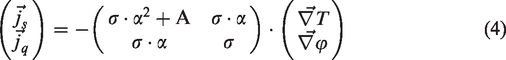
The thermoelectric tensor is made up of three tensorial quantities that are handled as scalars. These are the specific electric conductivity
Yarn materials
In Table 1, the yarn materials and their characteristics are presented. Merino wool (MW) and an elastic filament yarn (EY) produce the basic knit. The material is particularly suitable for use in functional underwear worn close to the body because wool quickly transports sweat to the outside, is kind to the skin and inhibits odor. 26 The elastic yarn is also used to make the knitted fabric even more flexible and close-fitting for optimum skin contact and heat transfer. The SY is used to manufacture the textile-based heating elements. Silver-tech+150 is PA 6.6 based and plated with silver, while Silver-tech 50 is a hybrid-twisted yarn with PA 6.6 and polyester plated with silver.
Yarn materials used for design the wearable heating structure
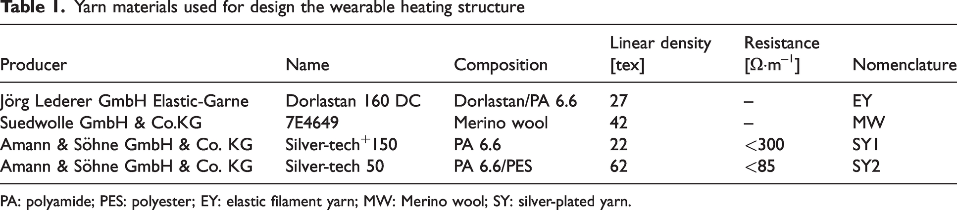
PA: polyamide; PES: polyester; EY: elastic filament yarn; MW: Merino wool; SY: silver-plated yarn.
Detergent
Table 2 presents the used detergent for evaluating wearable knitted heating structures with their relevant information according to the manufacturer's specifications. The detergent (DA) corresponds to reference detergent 3 according to DIN EN ISO 6330. 27
Reference detergent used for evaluation of wearable knitted heating structures

Manufacturing method
The flatbed knitting machine ADF 530-32 BW Knit & Wear with the machine unit E7.2 from H. Stoll AG & Co. KG (Figure 1) is used to manufacture the textile heating elements.
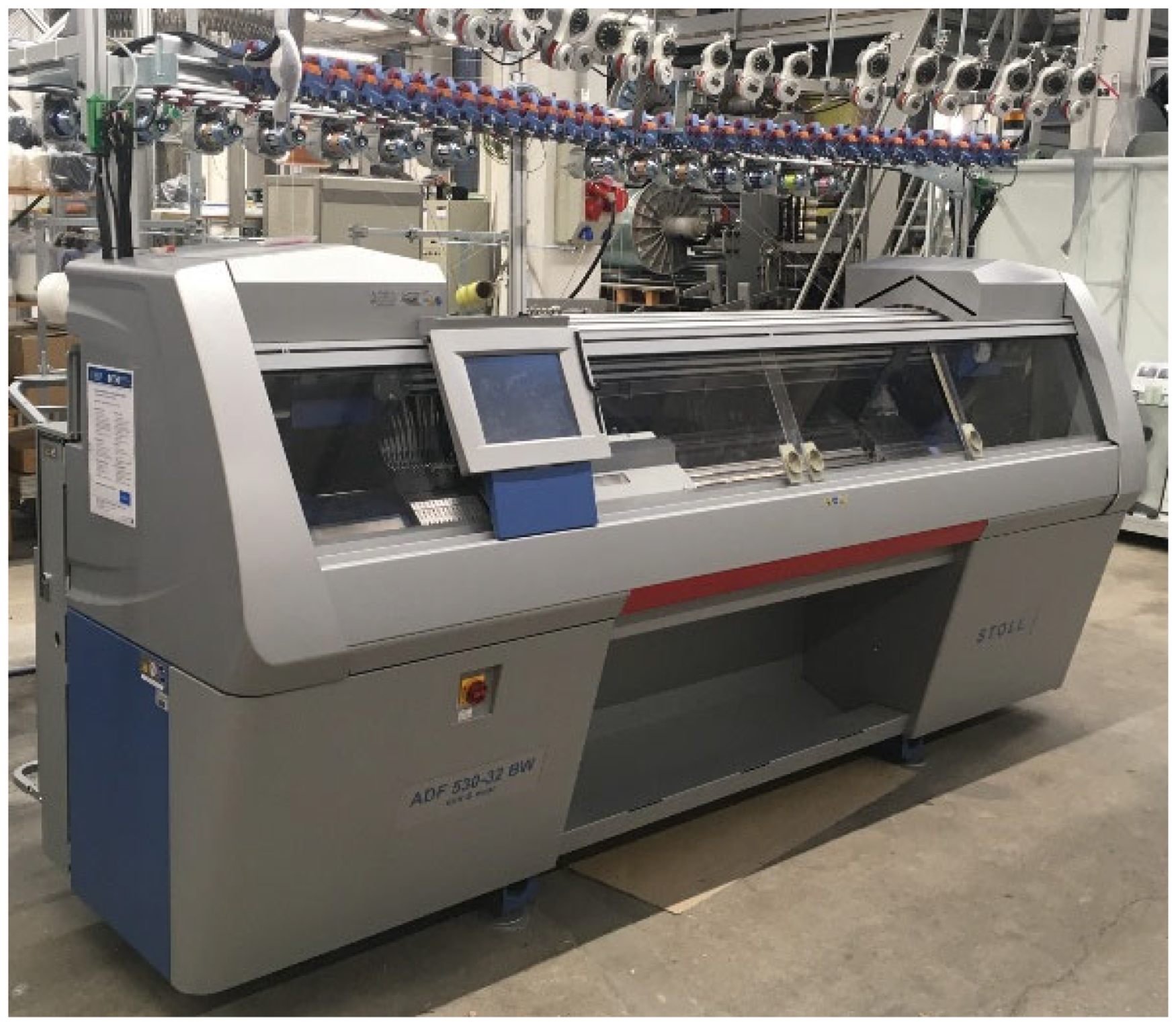
Flatbed knitting machine ADF 530-32 BW Knit & Wear.
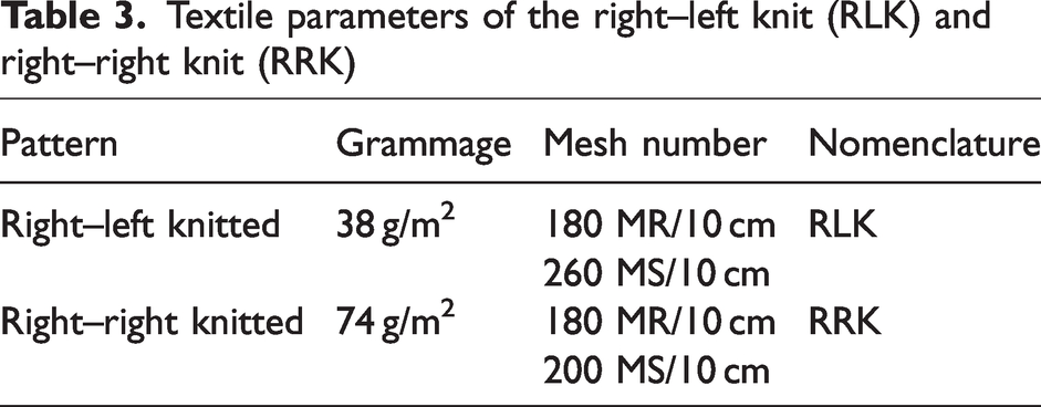
The knitted structures produced using the flatbed knitting machine have different textile parameters. These parameters can be found in Table 3.
Textile parameters of the right–left knit (RLK) and right–right knit (RRK)
Washability tests
For the washing tests with the developed wearable knitted heating structures, a reference washing machine type A (front loader, Miele Softtronic W 3923 WPS), according to DIN EN ISO 6330, 27 is used. Table 4 shows the washing and drying parameters used in the washing tests.
Washing and drying parameters for the evaluation of the wearable knitted heating structures due to washability tests
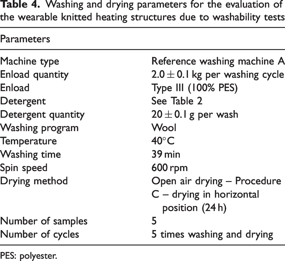
PES: polyester.
Measurement of thermal properties
The experimental setup shown in Figure 2 is used to characterize the wearable knitted heating structures. The temperature of human skin (32°C) is simulated utilizing a heating plate PZ 72 (c) with a PR 5 SR controller (e) from Harry Gestigkeit GmbH. Voltage and current measurements are made using a FLUKE 8846 A6 1/2 digit precision multimeter benchtop multimeter (h) manufactured by Fluke Deutschland GmbH. An E95 infrared camera (IR camera) from Teledyne FLIR LLC (i) is used to record the temperature and uniform heat distribution in the heating element. The temperature of the heating element is also determined by an additional contact measurement (g). The temperature measurement with the three sensors corresponds to T1 and T2 in the thermal images of the different geometries. The contact between the heating element and the voltage source (d) is made via crocodile clips (a). For this purpose, three type-K probes are placed on the cover material (g). The temperature in different zones of the heating element is determined via a VOLTCRAFT k204 Datalogger temperature measuring device (f).
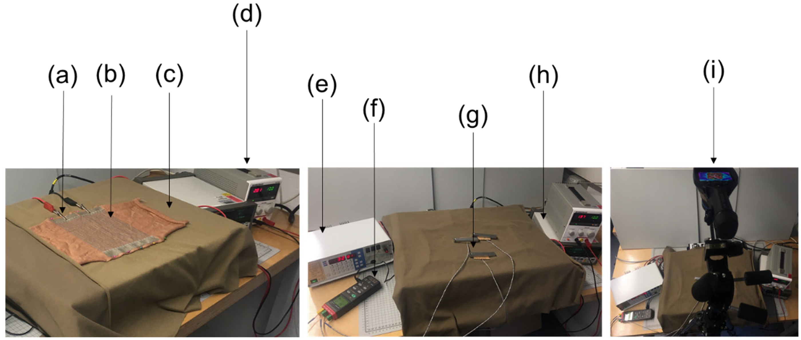
Experimental setup for measurement of thermal properties of the wearable knitted heating structures.
Results
Theoretical approach
From the current state-of-the-art, it appears that full-area (F), meandering (M) and parallel-connected circuits (P) are suitable for heating structures.7,19,23 As described above, most AWGs present an uneven heat distribution during use due to wrinkling, compacting and the effect of washing and care procedures. Thus, in this study, a new variant of designing heating structures based on the combination of serial sections with serially connected parallel circuits with spatial demarcations is investigated and given the name dedicated serial-parallel circuits for heating (DSPCh). The advantage of DSPCh is that the entire current applied to the heating structure flows in serial sections and the current is distributed within specially bounded circuits according to the respective heating demand. This makes it possible to generate heat efficiently within the designated parallel-connected sub-circuit. An additional advantage is that the entire system does not immediately fail in the case of a defective circuit, but the heating structure continues to function. The comparison of the heating geometries is depicted in Figure 3.
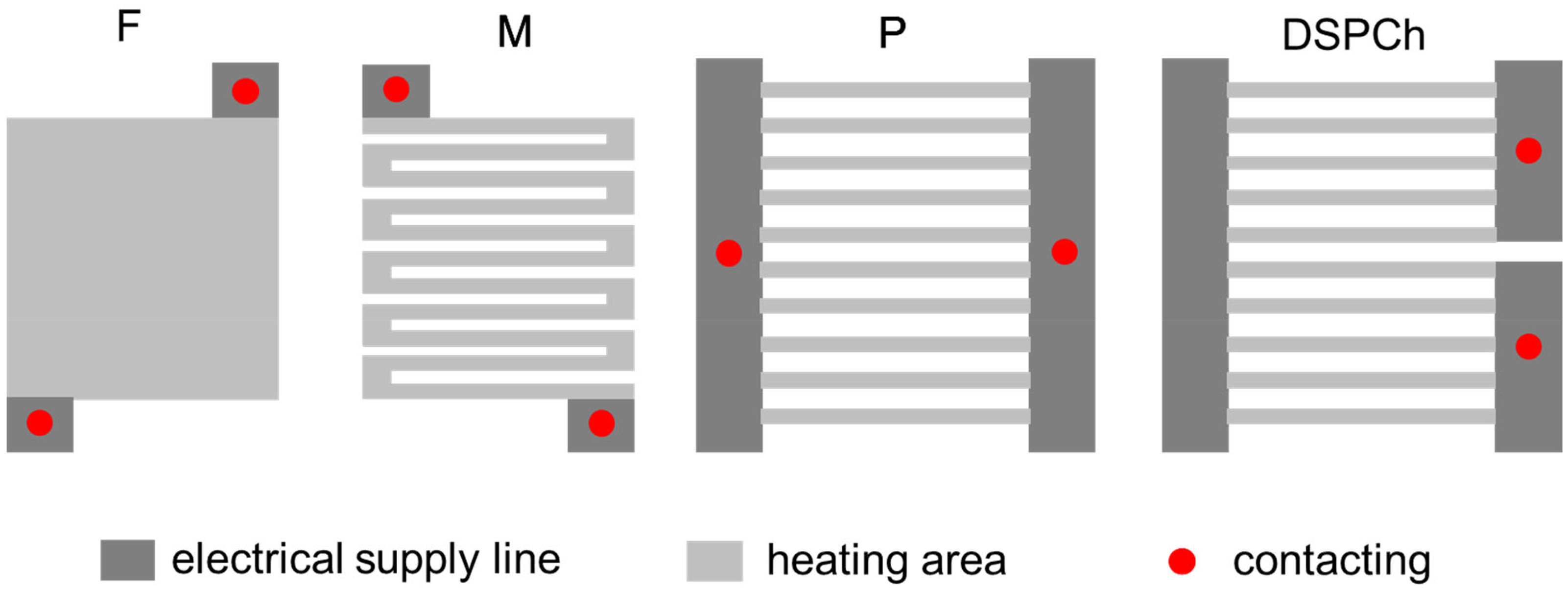
Geometry of the heating structures. DSPCh: dedicated serial-parallel circuits for heating.
The heating element geometries are divided into the electrical supply line and the heating area. Different materials are used for this, a low-resistance yarn SY2 in the supply line and a high-resistance yarn SY1 in the heating area.
This principle aims to ensure that the current can flow as loss-free as possible through the supply line to the heating surfaces so that the electrical power can be converted into thermal energy mainly and homogeneously at the aimed heating area and not in the supply line regions. A constant voltage is applied between the two contacting points. According to Equation (1), the power P increases when I increases and the voltage V remains constant. The increase in power corresponds to an increase in the temperature of the heating structure. 28 These are simulated to theoretically investigate the plausibility and current density and temperature distribution of the preliminary considerations during geometry development. The finite element software Ansys is used for the simulation. The current density and the resulting temperature are simulated. For this purpose, technical material data of the basic knit and the conductive yarns, such as isotropic resistance and thermal conductivity, are input. The resistances of the knitted structure were determined by integral measurements, adjusted in the simulation, and do not correspond to the specific resistances of the SY. In addition, the convective heat transfer coefficient αK has an essential role in the simulation and the empirical investigation of the heat distribution since more or less heat is transported away according to the airflow speed ν. The surface temperature is therefore directly influenced by this and cannot be neglected. For the simulation, a wind speed of 0 m/s is assumed, since this also corresponds to the laboratory environment for the empirical investigations and corresponds to the wearing situation. At ν = 0 m/s, α K corresponds to 3.5 W/m2K. 29 In the simulation, a constant thickness of 1 mm and an electrical voltage of 10 V are assumed as frame parameters. In addition, the temperature is simulated with the additional textile covering it. This corresponds to the real measurement situation, as can be seen in Figure 2. The assumptions and material parameters used for the simulation are summarized in Table 5.
Assumptions and material parameters used for the finite element method simulation
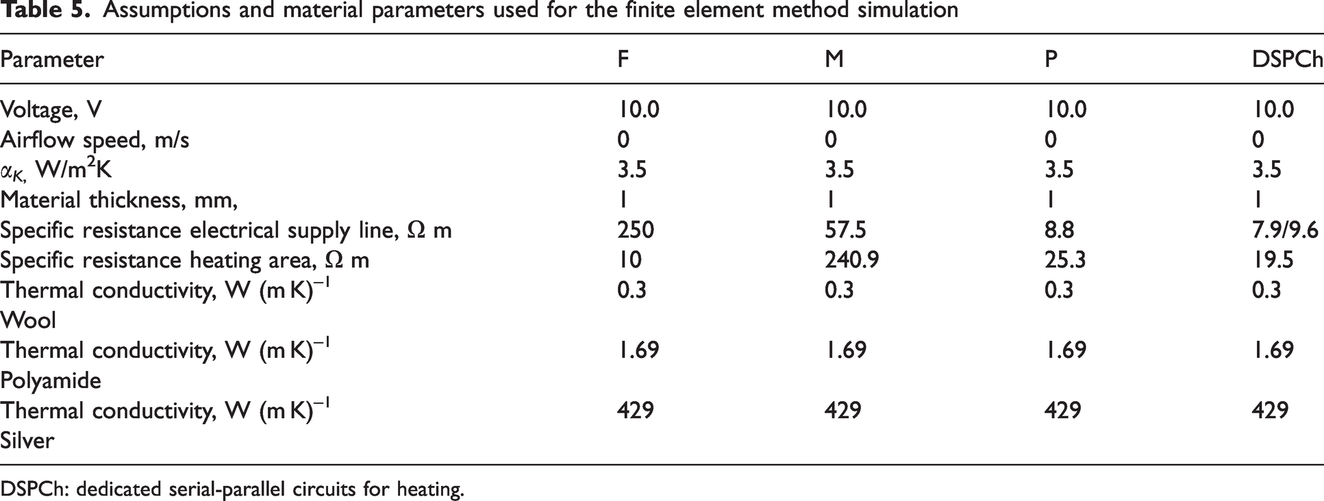
DSPCh: dedicated serial-parallel circuits for heating.
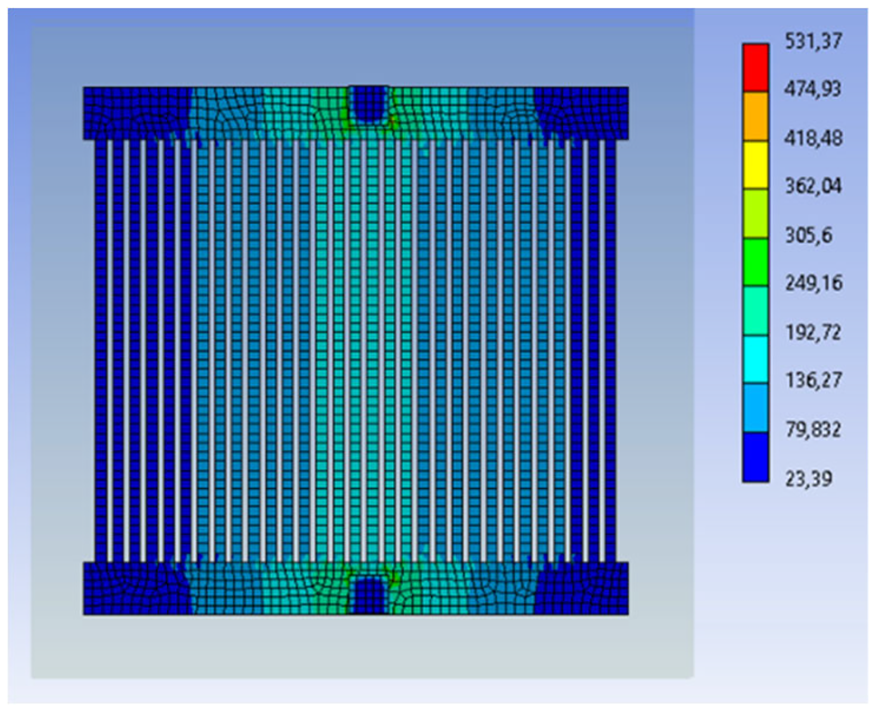
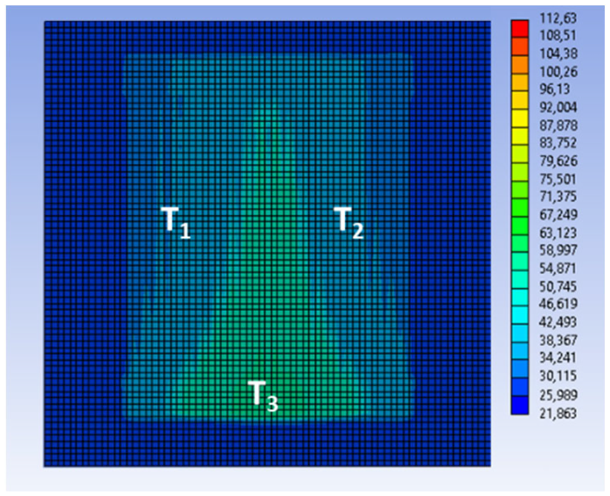
The results of the FEM simulations are shown in Figures 4, 5, 6, 7, 8, 9, 10 and 11. The simulation assumes a homogeneous textile, depending on the heat structure geometry. Figure 4 shows the current density distribution in mA/mm2 from geometry F. As can be seen, the current density is highest at the contact points and decreases significantly in the center of the heating structure. The resistivity ratio between the supply line and the heating zone is not ideal, so the current density is not uniform. Of course, this also has a corresponding effect on the temperature distribution of geometry F, because the current at the supply line is converted into heat. This relationship becomes clear when Figure 5 is compared. It can be seen that the temperature spreads from the contact points into the surface. The structure itself remains at an ambient temperature of 22°C, whereas hot spots of up to 108°C form at the contact points. Even in geometry M – its current distribution is shown in Figure 8 – a small current flows through the structure because the geometry-dependent electrical resistance is high. In this case, a long conductor with a small cross-section is present, which is relatively unfavorable for a heating structure. Therefore, the structure cannot heat up and remains at 22°C ambient temperature, as shown in Figure 9. Geometry P differs significantly from geometries F and M. As shown in Figure 12, the current is distributed between the two opposite contacting points running heating elements, so that the temperature should also spread from the center outwards. The FEM simulation of the temperature distribution in Figure 13 shows a uniform distribution between 54°C and 56°C on the surface of the cover. The electro-thermal FEM results of the simulation are shown in Table 6.
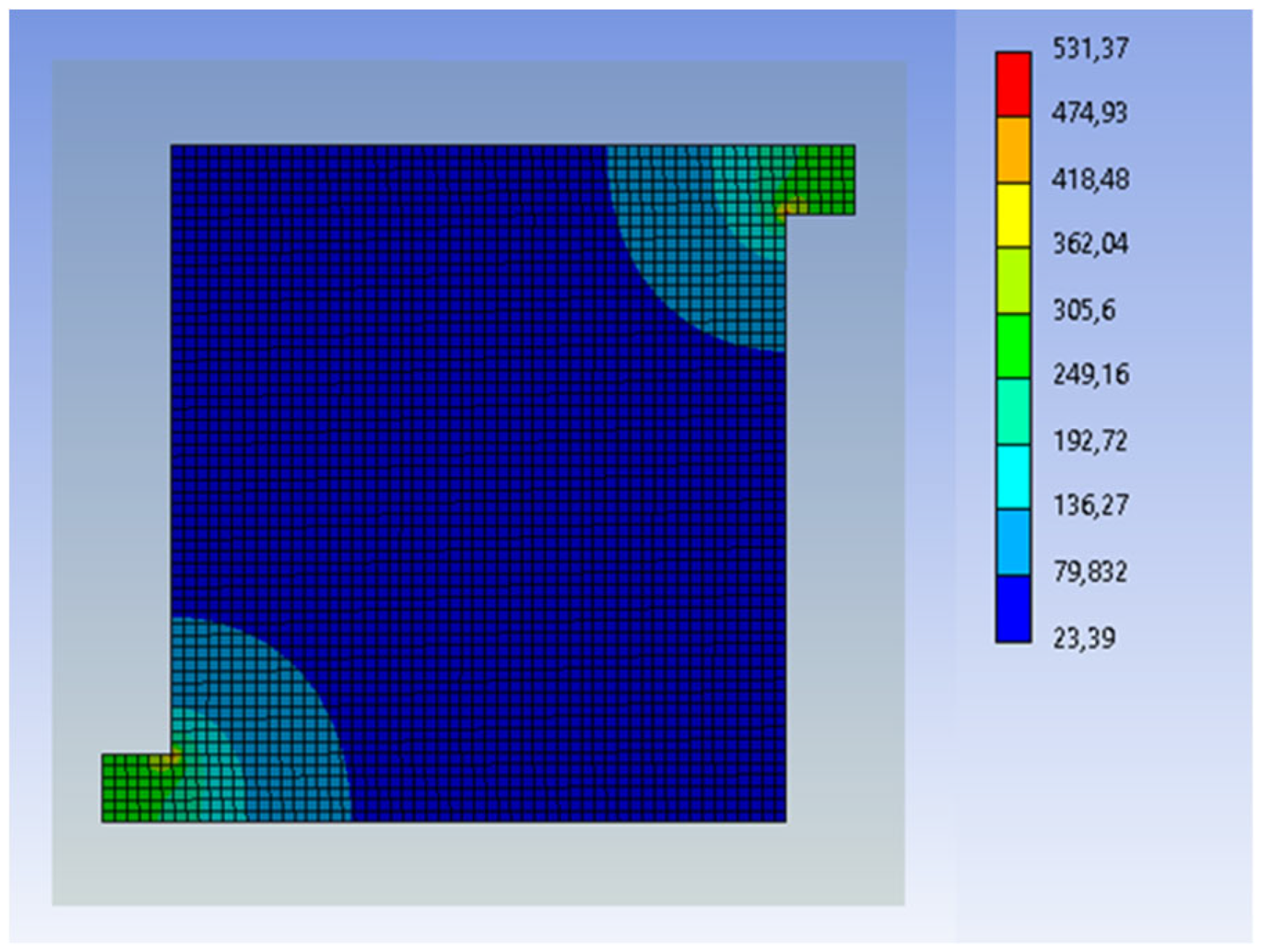
Finite element method simulation from current density distribution [mA/mm2] from geometry F.
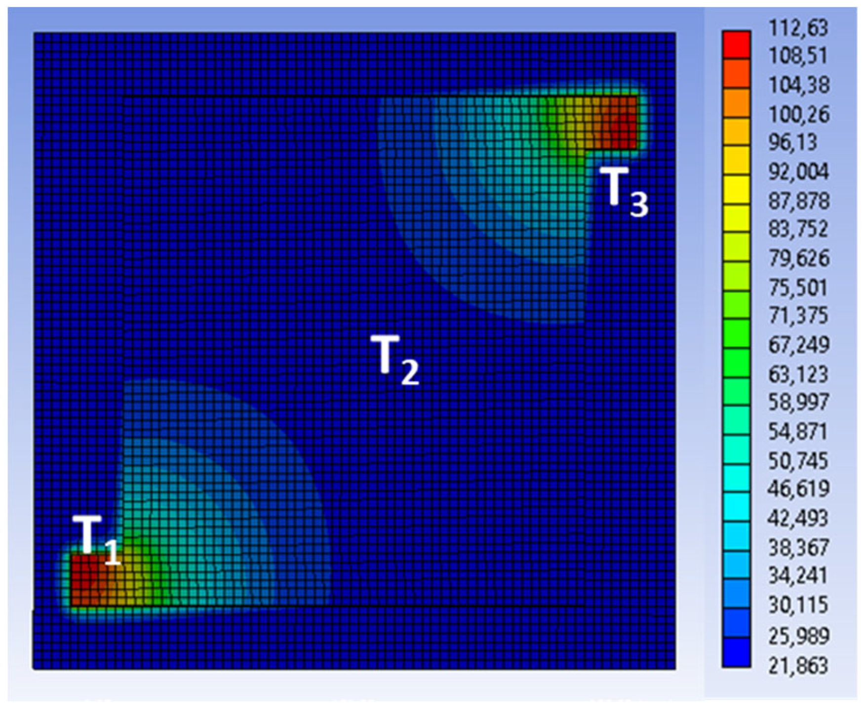
Finite element method simulation from distribution of temperature [°C] from geometry F.
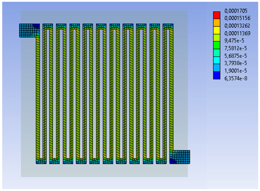
Finite element method simulation from current density distribution [mA/mm2] from geometry M.
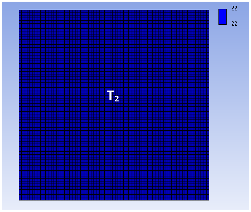
Finite element method simulation from distribution of temperature [°C] from geometry M.
Finite element method simulation from current density distribution [mA/mm2] from geometry P.
Finite element method simulation from distribution of temperature [°C] from geometry P.
Finite element method simulation from current density distribution [mA/mm2] from geometry dedicated serial-parallel circuits for heating.
Finite element method simulation from distribution of temperature [°C] from geometry dedicated serial-parallel circuits for heating.
Finite element method simulated electro-thermal conditions of the four different geometries
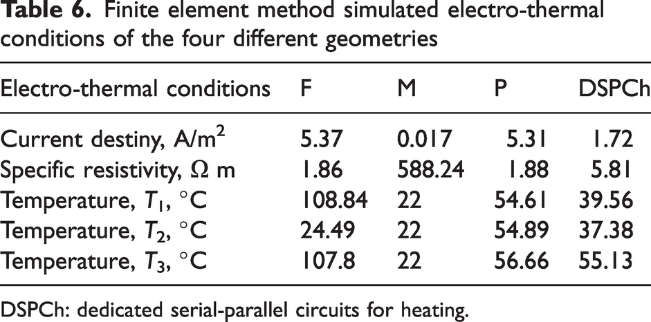
DSPCh: dedicated serial-parallel circuits for heating.
The last geometry DSPCh shows a uniform current distribution in the upper and lower area of the two parallel-connected heating structures. In the middle, however, the current distribution is higher at the transition point between the two parallel-connected heating structures, as shown in Figure 12. This is also reflected in the simulation of the temperature distribution, which can be seen in Figure 13. The central part is the warmest at 55°C and the temperature decreases to 37°C towards the outside. According to the theoretical consideration, pattern DSPCh is the most suitable because of the highest uniformity.
Thermal image from geometry M as the right–left knit.
Thermal image from geometry M as the right–right knit.
Electro-thermal characterization
In the following section, it is investigated whether the empirical results differ from the simulation. After the theoretical investigation, the different geometries are practically implemented and evaluated. Based on the findings of Li et al.'s publication, 22 wool and SY are particularly well suited for the development of body-worn garments with integrated heating structures.7,19,20 For this reason, the heating structures, shown in Table 7, are knitted from MW with SY. The materials used are given in Table 1.
Different geometries of the right–left knit (RLK) and right–right knit (RRK)
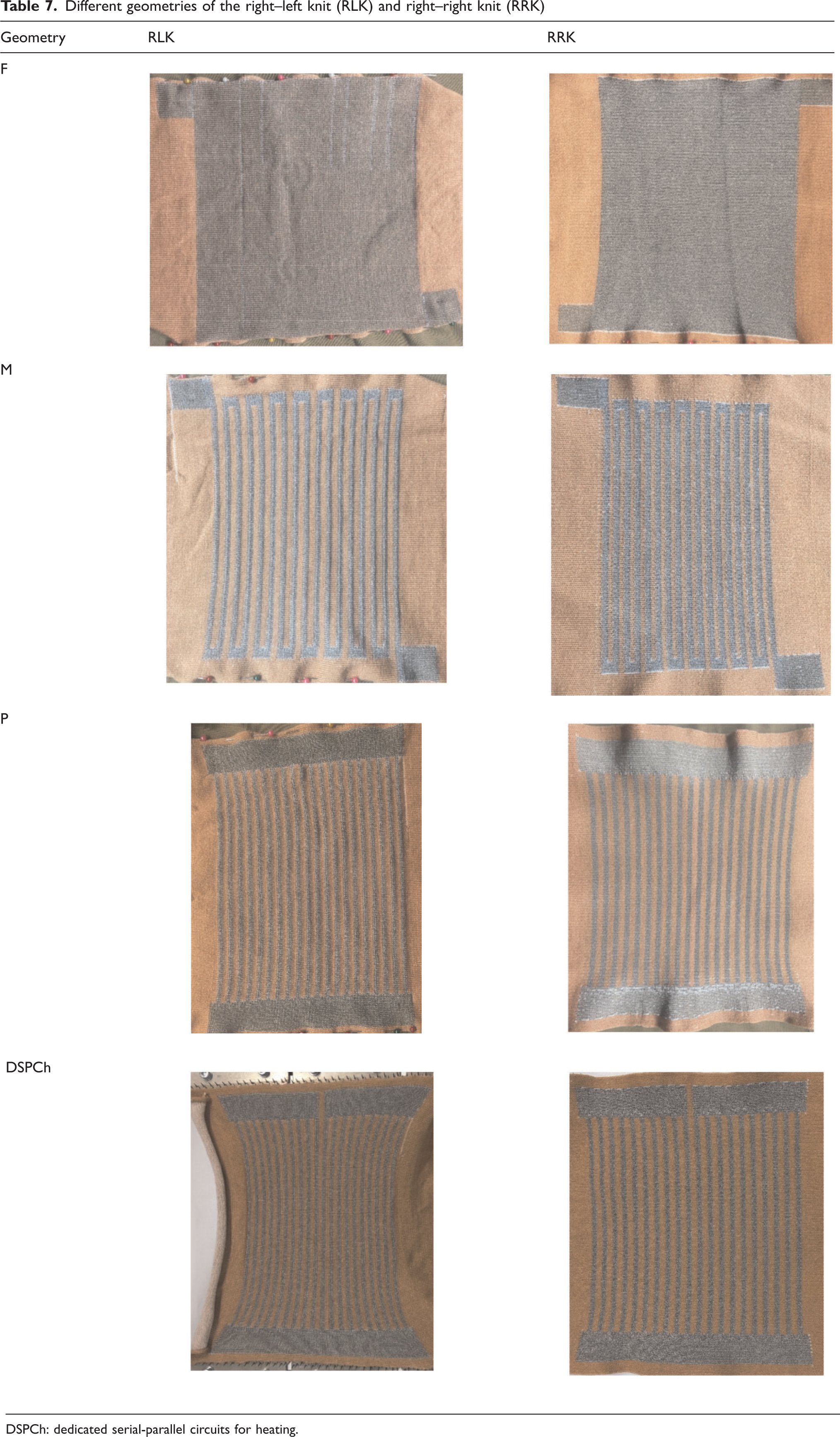
DSPCh: dedicated serial-parallel circuits for heating.
Subsequently, the different patterns are electro-thermally characterized. As explained in the introduction, two different patterns are compared. In the right–left knit (RLK) and right–right knit (RRK), different amounts of SY are processed, thus affecting the electro-thermal conditions as described above. Tables 8 and 9 show the results of the electro-thermal characterization. The results were obtained using the test setup shown in Figure 2. As explained in the Material and methods section, the temperatures T1–T3 are measured with sensors since the thermograph temperature data are less accurate.
Electro-thermal conditions of the four different designs of the right–left knit
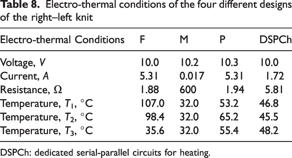
DSPCh: dedicated serial-parallel circuits for heating.
Electro-thermal conditions of the four different designs of the right–right knit
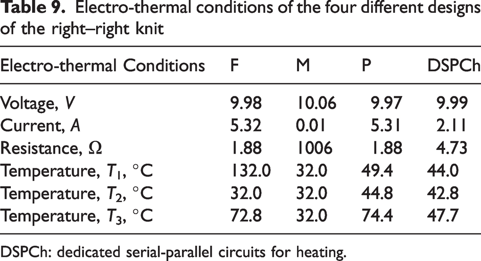
DSPCh: dedicated serial-parallel circuits for heating.
Comparison of the theoretical approach and empirical results
The thermal image indicates a current destiny distribution of pattern F leading to local hot spots at the transitions between the supply line and the heating structure which can be seen in Figure 14 and 15. In some cases, these areas reach temperatures of over 100°C, although large areas within the heating structure do not exceed 32°C. The reason for this is that the amount of current flowing is not sufficient to heat the entire area and a higher voltage would have to be applied, which is not permitted for safety reasons for use in clothing. Therefore, a full-area circuit geometry is not suitable for heating structure applications. The results of the FEM simulation and those of the empirical investigation are in good agreement, as evident in the following figures.
Thermal images from geometry F as a right–left knit.
Thermal image from geometry F as the right–right knit.
Due to the high resistance in pattern M, any current flows at a constant voltage of 10 V, so that the temperature in the heating zone does not rise above that of the heating plate of 32°C. This is confirmed by temperature measurement with sensors T1–T3. The corresponding measurement data can be found in Tables 8 and 9. This result was also expected according to the theoretical prediction. This geometry is also not suitable for the intended application due to its high electrical resistance.
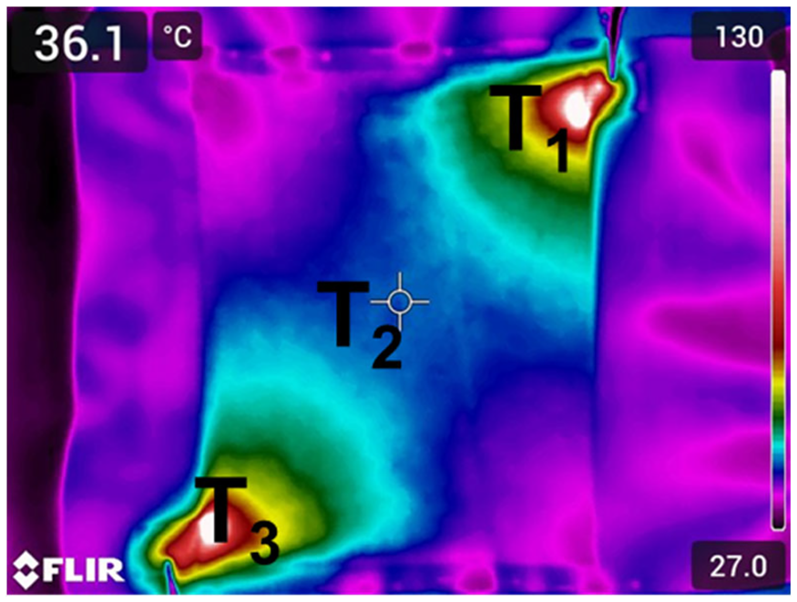
Geometry P heats up unevenly with a temperature difference between the central and peripheral regions of up to 12 K (RLK) or 25 K (RRK). Local hot spots occur at the contact points in the feed zone which can be seen in Figure 16 and Figure 17. The evaluations and simulations indicate that the current takes the path of least resistance and, accordingly, only the central part is heated. The current does not primarily flow along the supply line and then into the heating structures, but rather directly from the contact area into the heating structures.
Thermal image from geometry P as the right–left knit.
Thermal image from geometry P as the right–right knit.
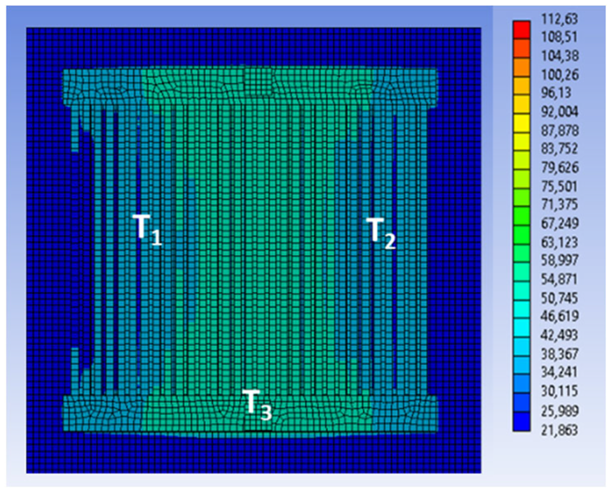
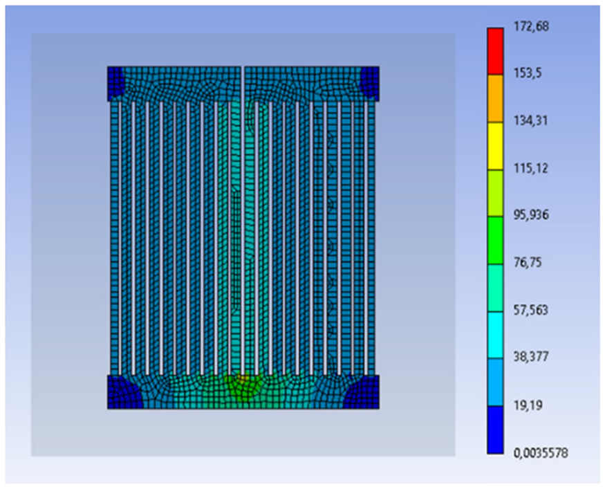
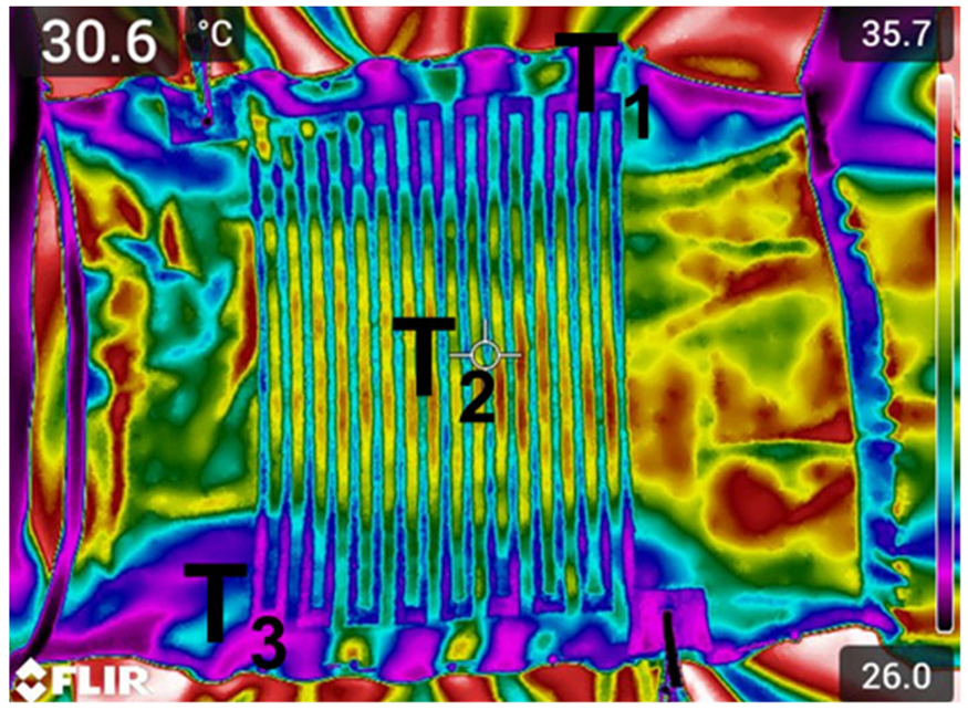
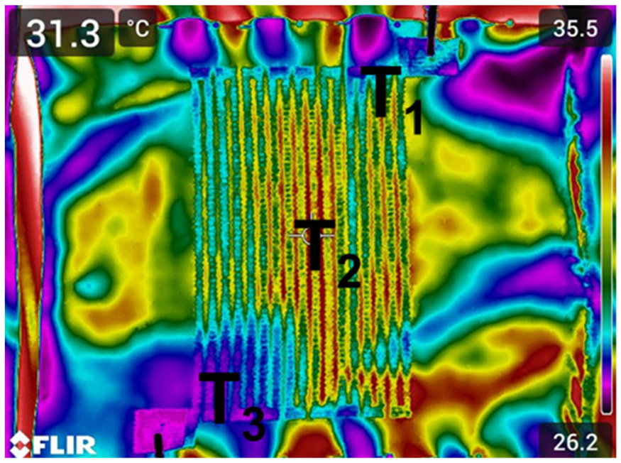
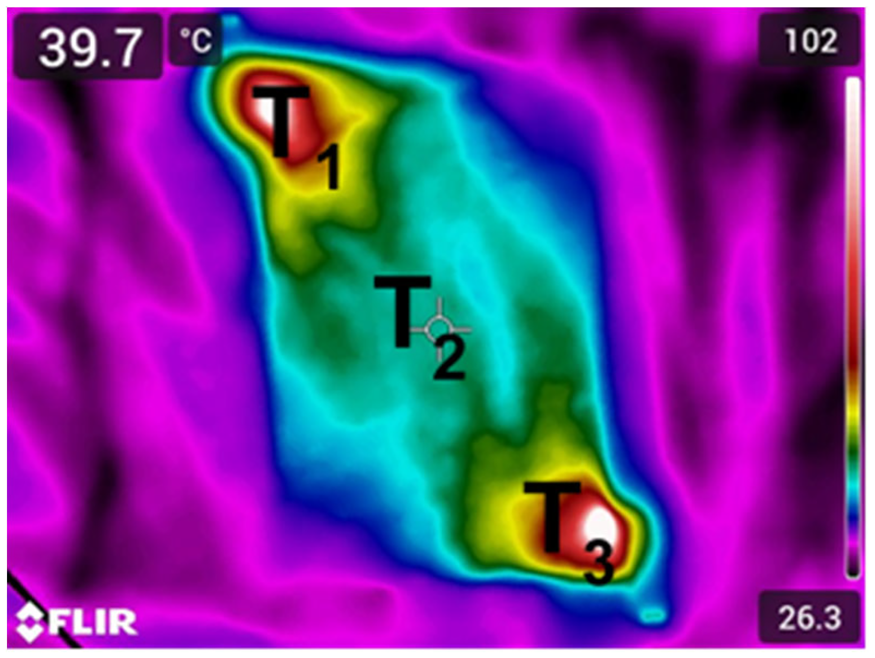
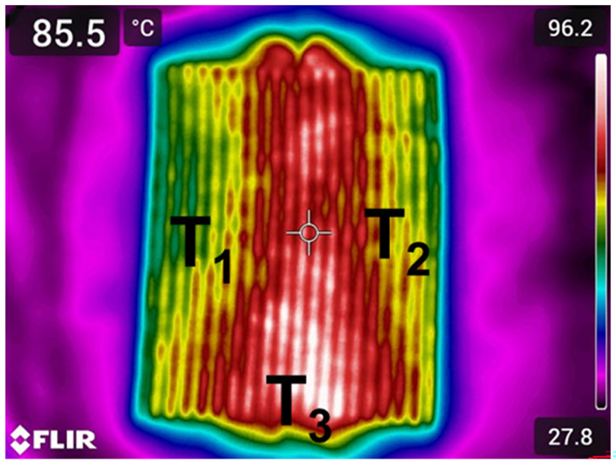
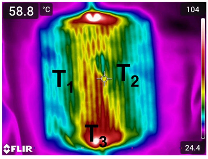
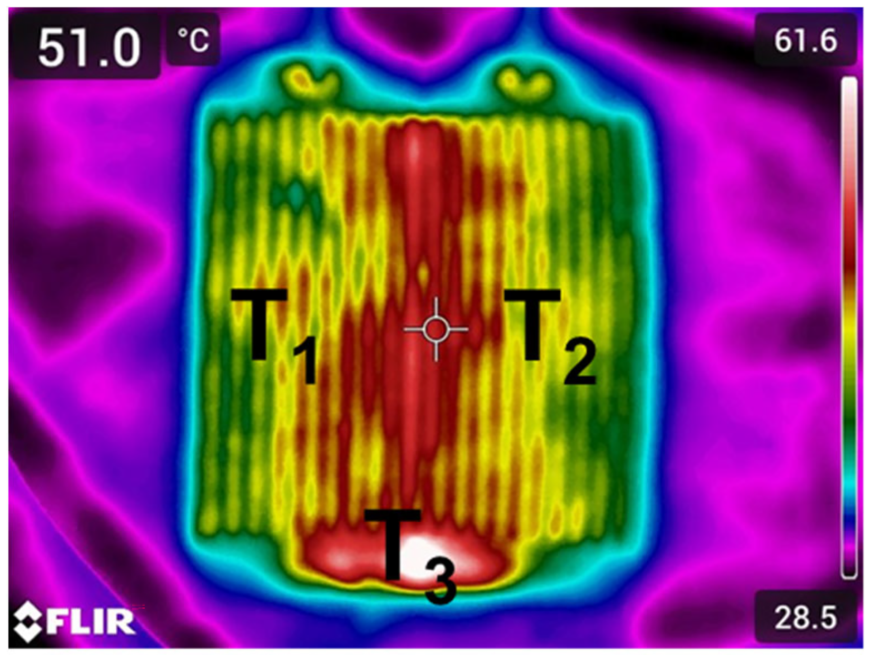
In the case of the DSPCh pattern with RRK binding shown in Figure 18 and Figure 19, a hot spot appears at the junction of the two parallel circuits connected in series. The thermal image of the DSPCh pattern with RLK binding shows an acceptable uniformity of heat distribution in the heating surface. The yellow areas of the pattern (T1, T2) were checked with the temperature sensors. The maximum temperature deviation of this pattern is less than 3 K and leads to small hot spots at the junction of the two parallel circuits connected in series, which is not critical due to the small temperature deviation. In the DSPCh design, the current is shared between the two parallel circuit blocks, the parallel circuits are all supplied with a constant voltage and the heat distribution is the most uniform compared to the other three geometries. Accordingly, for a textile heating structure in functional underwear worn close to the body, a combination of circuits connected in series and in parallel is the most suitable in comparison to the widely and typically used circuit layouts. The uniformity for the RLK is higher than for the RRK. The reason for this is that the supply line of the RRK has less electrical conductivity concerning the parallel circuits, so the knitted fabric heats up more unevenly. The low electrical conductivity is due to the type of knitting because, in the RRK, the meshes are transferred from the front to the rear needle bed staggered, so there is less contact between the meshes from the SY. Therefore, the contact resistance within the RRK is higher than that in the RLK, where all the meshes are next to each other and, therefore, in complete contact.
Thermal image from geometry dedicated serial-parallel circuits for heating as the right–left knit.
Thermal image from geometry dedicated serial-parallel circuits for heating as the right–right knit.
Washing and care processes
Due to the uniform heat distribution within the heating element and the developing temperatures of maximum 48°C at a constant voltage of 10 V, only the DSPCh design with the RLK is considered for the evaluation of the influence of the washing and care processes.
Before the samples are washed and dried five times, the electro-thermal conditions of five samples are determined. The results of the comparison between before and after washing are shown in Figure 20.

Electro-thermal conditions before and after five cycles of washing and drying.
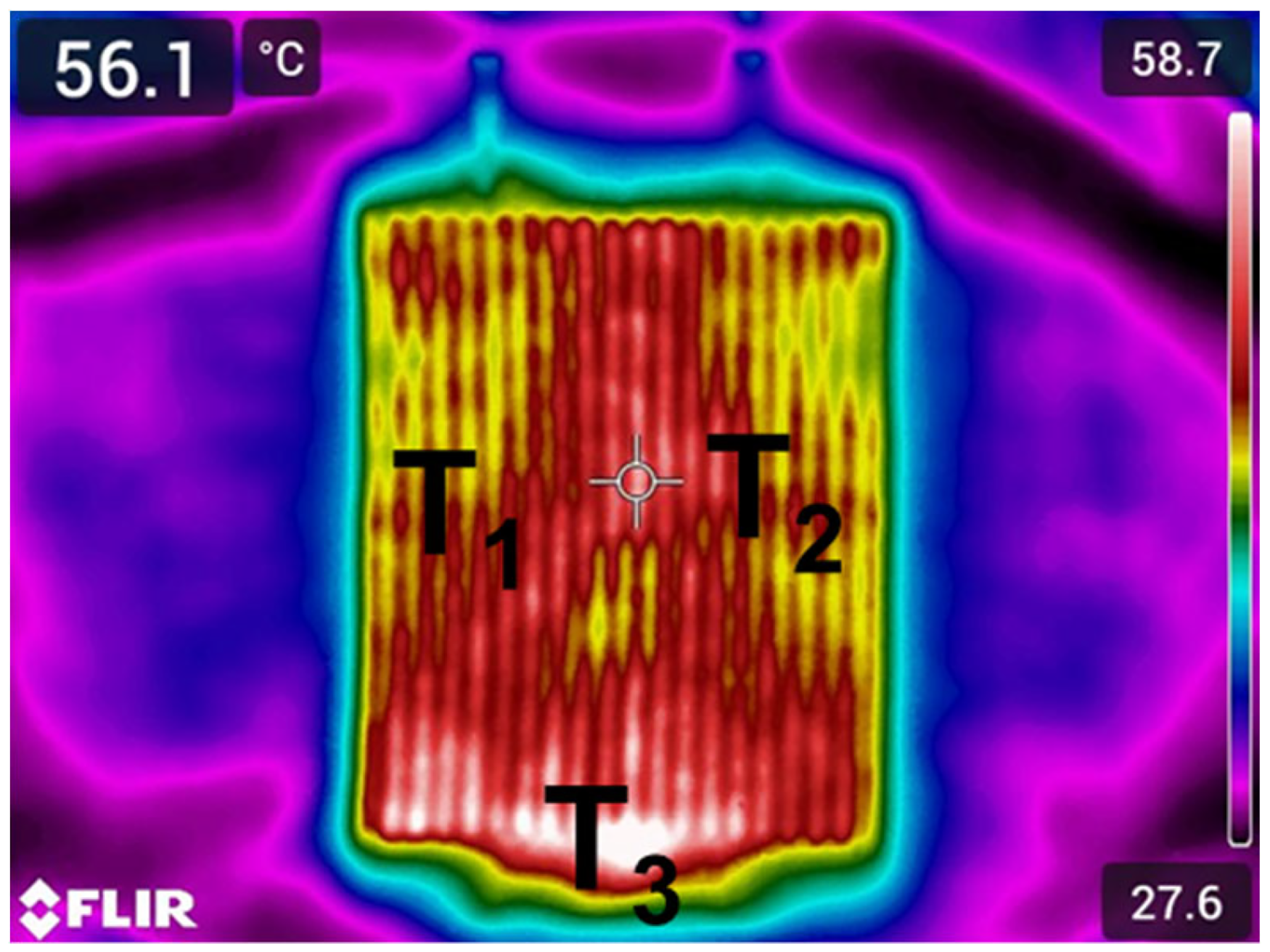
As shown in Figure 20, the washing has an influence on the electrical-thermal conditions of the heating structures. It can be seen that the current increases by 7.6% and the resistance decreases by 7.05%. An explanation for this unexpected behavior for the decreasing electrical resistance15,16,18 may be detergent residues on the heating element, which are electrically conductive. The standard detergent contains different salts and silicates. 30 In particular, it contains a high proportion of various sodium carbonates, other salts and silicates, which are electrically conductive when dissolved in water.31,32 Temperatures T1 and T2 increase by 4.5% and 5%, respectively. The temperature increase of 13.5% at T3 is the highest. The temperature increase can also be seen in the thermal images in Figure 21.
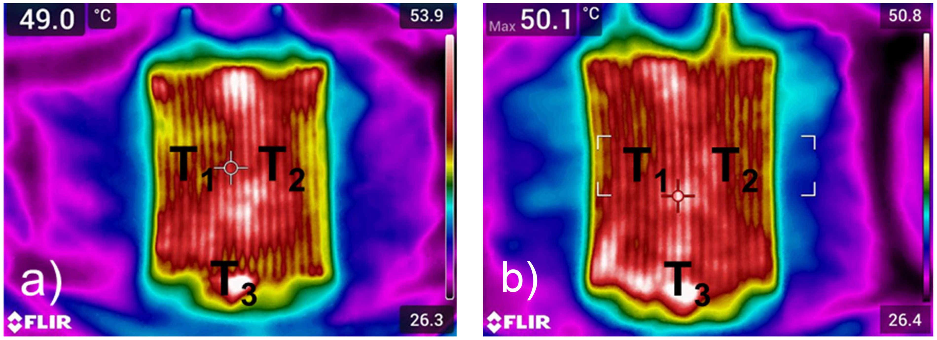
Thermal image of (a) dedicated serial-parallel circuits for heating (DSPCh) design right–left knit (RLK) before washing and (b) DSPCh design RLK after five cycles of washing and drying.
In addition to the temperature increase, the heating field heats more uniformly overall because of the detergents on the surface. After five washing cycles, the function of the heating elements is still as given and is not degraded by the washing process. To statistically confirm this conclusion, a two-sample t-test was performed on dependent samples. The null hypothesis that the washing does not degrade the function of the heating elements is assumed. The calculated value for the t-statistic is –1.65. Accordingly, the magnitude of the t-value is smaller than the critical t-value, which is 2.02. The p-value of 0.08 is more significant than 0.05. The null hypothesis is thus confirmed.
Conclusion
In summary, four different circuit geometries based on two knitting bindings with two different SYs have been developed, simulated, fabricated and investigated. The influence of the binding integration of the conductive circuits on the uniform heat propagation within the knitted heating structure was also investigated. The tests showed that the SYs are suitable for use in heated functional underwear and that the heating performance is determined by the knitted binding integration. The combination of serial-parallel circuits defining designated areas for heating, coined as DSPCh, showed uniform heat distribution with adaptable temperatures including ranges suitable for textiles worn close to the body. In comparison to heating element designs (full-surface, serial and parallel conductor arrangements) used in state-of-the-art and typically employed ST circuit designs, the DSPCh structures feature comfortable heat levels and by design exclude risks such as burning or electric shocks. The experiments conducted in order to target uses for garments worn on the skin or close to the body show that the structures are washable and that their electrical-thermal properties are influenced by washing and care processes in a minor manner. The influence of the washing and care protocols is negligible for the heating performance. The investigations have shown that the knitted DSPCh structures with SYs are suitable for AWGs.
The fundamental findings from the current state-of-the-art were combined to knit a fully functional textile-based heating element based on the DSPCh principle. The textile heating structures were simulated using the FEM to estimate the temperature deployment as a result of applied voltage. The temperature development with SYs in combination with the circuit and knit design as well as the influence of the washing and care processes on the heating function were determined. With this work, a new textile-based heating element and a simulation-based design principle for garments close to the body has been developed and thus contributes significantly to expanding the current state-of-the-art in intelligent textiles.
Smart heating textiles are an exciting and rapidly developing field of research with many potential applications. Further research in this area will likely focus on several critical areas in the future. One crucial area of study will be the development of new, more energy efficient heating yarns that can be integrated into a wide range of knitwear garments. These new yarns may use advanced materials or manufacturing techniques to improve their performance and reduce energy consumption. Another area of research will be the development of smart knitwear that can regulate body temperature and enhance comfort in various environments. These may involve using sensors to monitor body temperature and adjust the heating yarns or developing more advanced knitwear materials that respond to ambient temperature and humidity changes. Finally, further research in this area will likely explore the potential applications of smart heating textiles beyond traditional garment design. This may include the development of intelligent textiles for use in medical or athletic contexts or the creation of novel textile-based heating systems for use in a range of industrial or commercial settings. Overall, the field of heating textiles is an exciting and rapidly evolving area of research with many potential applications. As new technologies and materials continue to be developed, we expect to see further innovations in this area in the years to come.
Footnotes
Acknowledgement
The authors would like to thank the Research Institute for Materials, Fuels and Lubricants, Germany for support of the work reported this paper.
Declaration of conflicting interests
The authors declared no potential conflicts of interest with respect to the research, authorship, and/or publication of this article.
Funding
The authors disclosed receipt of the following financial support for the research, authorship, and/or publication of this article: The authors would like to thank the Research Institute for Materials, Fuels and Lubricants, Germany for support of the work reported this paper.