
Abstract
The rise of interest in wearable sensing of bioelectrical signals conducted via smart textile systems over the past decades has resulted in many investigations on how to develop and evaluate such systems. All measurements of bioelectrical signals are done by way of electrodes. The most critical parameter for an electrode is the skin-electrode impedance. A common method for measuring skin-electrode impedance is the two-lead method, but it has limitations because it relies on assumptions of symmetries of the body impedance in different parts of the body as well as of the skin-electrode impedances. To address this, in this paper we present an easy-to-use and reliable three-lead in vivo method as a more accurate alternative. We aim to show that the in vivo three-lead method overcomes all such limitations. We aim at raising the awareness regarding the possibility to characterize textile electrodes using a correct, accurate and robust method rather than limited and sometimes inadequate and uninformative methods. The three-lead in vivo method eliminates the effect of body impedance as well as all other contact impedances during measurements. The method is direct and measures only the skin-electrode impedance. This method is suitable for characterization of skin-electrode interface of textile electrodes intended for both bioelectrical signals as well as for electrostimulation of the human body. We foresee that the utilization of the three-lead in vivo method has the potential to impact the further development of wearable sensing by enabling more accurate and reliable measurement of bioelectrical signals.
Keywords
Over the past two decades there has been an interest to investigate the possibilities for the integration of measurements of different biopotential signals, perhaps most frequently the ECG, into different forms of textile garments.1–6 The possibility to use textile garments for electrostimulation has also been investigated.7–10 The rationale for this endeavour is often to alleviate the load on the healthcare sector. The European Union anticipates that technological innovations such as e-textiles could aid in the so-called silver-economy by providing means for health monitoring. 11 Many researchers strive towards a degree of integration where the electrodes are integral parts of the fabric of the garment. The way to realize this integration is then oftentimes to utilize electrically conductive yarns or fibres. These yarns are used to knit or weave the electrodes at specific sites when producing the fabric while the rest of the fabric is made of some nonconductive yarn. Techniques such as intarsia knitting and jacquard weaving make this way of producing electrodes possible. Other ways include the use of specific fabric made exclusively of conductive yarns that are cut and sewn to form the electrodes or by coating a fabric with conductive material. A recent review of textile-based electrodes and how to evaluate them by Le et al. gives at hand that the topic is of high interest to the research community and that there is a need for a standardized way of evaluate them. 12
The usability of the electrodes relies on their performance to let current pass across the interface with the human skin. To evaluate a candidate electrode, it needs to be characterized for this ability. One very common property that is reported is the sheet resistance of the fabric that constitutes the electrode,13–15 or sometimes just the resistance of a particular electrode. 1 This value can provide an indication of how the electrode will perform; however, by itself it is not a reliable indicator to predict the performance. The resistance and sheet resistance are also of significant importance when designing the conductive leads interconnecting different element of the textile-electronics measurement systems. The currents flowing in the fabric are currents of electrons. The currents flowing in the human body are currents of ions. The impedance between the out-of-plane of the fabric and the human body will thus depend on many other factors in addition to the resistance of the electrode material. The electrode will function as a transducer that converts ionic currents to electronic currents and vice versa. In other words: there is no transport of charge carriers across the interface but rather the movement of the charged particles in the body will present a time varying electrical field seen by the electrode and a redistribution of the free electrons in the metal side will result. Sometimes the current running through the skin-electrode interface is referred to as a displacement current (no material transport across the interface) and the equivalent electrical circuit models for such systems include capacitances which make the impedance frequency dependent. 16 Strictly speaking it is not a displacement current because of the presence of free moving charges in the body. This ability to transduce an ionic current to an electronic current is the most significant measure of a biopotential electrodes usability. A large portion of this interface impedance stems from different properties of the skin such as water content, concentration of charged particles, the presence of fat, sweat, dead tissue etc. These circumstances make the value of the skin-electrode impedance vary depending on where on the body the electrode is situated, when in time a measurement is taken, from person to person. In other words, the variability of the skin-electrode impedance is quite large. 17 Resistance and sheet resistance does not provide sufficient information to judge if a candidate electrode will perform as desired.
There is a need to extend the measurements to include the skin-electrode impedance in the relevant frequency span for the intended application of the electrodes.18,19 Some studies have recognized the contact impedance as being a crucial parameter, and have used either method for estimation of its magnitude by in vivo two-lead measurements at discrete frequency points, 20 or in vivo two-lead frequency sweep measurements, 13 or two-lead frequency sweep measurements on in vitro systems 21 that do not reflect the actual working conditions when used on a human body. In this article we suggest an easy-to-use and affordable method for conducting measurements that will give at hand realistic values. These will immediately provide an indication as to whether the sample at hand is feasible or not. In the following sections we will quickly describe the skin-electrode interface and some models of its conduction. We will present two cases: one in which a liquid electrolyte resides between the electrode and the skin (typical for conventional wet electrodes) and one in which there is no electrolyte present (typical for dry electrodes, as in the case of textrodes) and the commonly used electrical circuit models for these cases. Ultimately, we describe a method of taking in vivo measurements of the skin-electrode impedance that will provide useful readings for the development of textile electrodes.
Background and theoretical assumptions
Electric current at an interface
The skin-electrode interface is rather complex, but even in the case of two contacting macroscopically smooth metal surfaces there is a certain contact impedance. Mostly this stems from the constriction of the current to pass via the microscopic contacting points between the contacting members; this is called the constriction resistance. The areas where the contacting members do not touch each other will act as a capacitor in parallel with the constriction resistance. Figure 1 shows a schematic illustration of the constriction of the current at an interface.
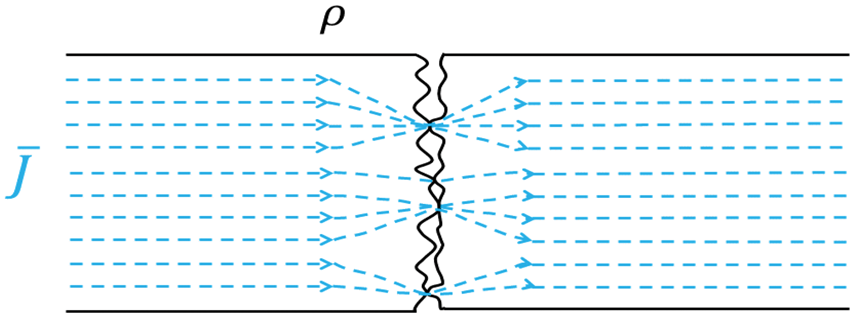
The current
In the case of a time-varying current, the small gaps between the contacting points act as capacitors and allow some displacement current to flow as well. Furthermore, in most cases, there will be impurities in the form of grease and oxides present on the surfaces that will also contribute to alter the conduction of current. These surface phenomena have been described in detail by Ragnar Holm and other scientists following him.22,23 In essence, even in the case of two solid metal pieces there is an addition to the total impedance in the form of a contact impedance. Such a circuit cannot be described merely by the resistivities of the mating metal pieces and their macroscopic geometries. From an engineering point of view, one needs to bear in mind the intended application of the construction one seeks to materialize. In some cases, the contact resistances might pose a problem and other times not. However, in the case of a textile electrode intended to interface with the human body the mere geometry will set conditions that force one to consider the contact impedance.
Sheet resistance
Sheet resistance is a material parameter used for thin films. In order to be able to use the term at all, the conductive body needs to have a homogeneous thickness. The sheet resistance,

The skin-electrode interface
The electrical currents in the body mostly consist of flowing ions and other charged particles. In contrast, the currents in electrical leads always consist of flowing electrons; this is most of the time also true for electrical devices. The skin-electrode interface thus needs to transduce the different kinds of currents to the other kind. Ideally, the interface should present no impedance at all in any direction, but this scenario is not attainable in the real world. The interface will present a certain impedance that restricts the flow of current across the interface. It is worth bearing in mind that when we talk about currents crossing the interface it is just that: a current but not necessarily any transportation of particles across the interface. All dry so-called polarizable electrodes of which pure metallic electrodes are examples depend on displacement currents. The moving particles on one side of the interface give rise to a charge distribution that changes in time and this changing charge distribution alters the electrical field which induces a movement of charged particles on the other side of the interface. In addition to displacement currents, some (wet) electrodes have other mechanisms for the current to pass the interface like redox reactions at the electrode. It is thus a question of how the medium that constitutes the interface reacts to the time varying electrical field that determines the impedance of the interface. This is a totally different way of electrical conductance compared with the sheet resistance or, for that matter, bulk resistance in a conductor, as discussed in the previous section. Hence there is no theoretical ground for believing that the two parameters, sheet resistance and contact impedance, should be correlated. The magnitude and phase shifting behavior of this interface will depend on a large number of factors, most of which stem from the properties of the skin like water content, ion concentration, number of dead cells, amount of fat tissue, number of sweat glands and so on. In addition to these physiological factors also the geometry of the interface will influence the contact impedance. Different circuit theoretical models of varying levels of complexity have been proposed for the contact impedance between metallic electrodes and the human skin, also for the case of textile electrodes. See for instance Beckmann et al., 21 Medrano et al. 26 and Webster and Clark 27 for detailed discussions of these models. In addition, it is important to note that many of these were conceived first as empirical models that aimed to fit experimental data, rather than being strictly based on physical principles. As such, they sometimes include resistive elements simply as a means of achieving a better fit to the experimental data, even if they do not fully explain the underlying physical mechanisms at play. Grimnes and Martinsen discusses the use of these models as either descriptive or explanatory. 28
Most often disposable electrodes are equipped with a layer of conductive gel. This gel has two benefits when it comes to contact impedance: first, it lowers the magnitude of the impedance and second it secures the relative position of the electrode on the skin. The conductive gel will fill out any cavities between the electrode and the skin and hence those volumes will be characterized by a (very low) pure resistivity. The electrolytes in the gel aid in the redox reactions at the interface. In the case of textile electrodes one long term objective is to make them operate in a dry state. A dry skin-electrode interface, textile or not, will most often have some cavities of air between the electrode and the skin. These cavities will act as capacitive elements in the contact impedance. The lack of electrolytes also obstructs the redox reactions. A sketch of the model for a dry skin textile electrode proposed by Beckmann et al. is depicted in Figure 2.
21
The different ideal components model the various mechanisms of current transduction across the skin-electrode interface. Each
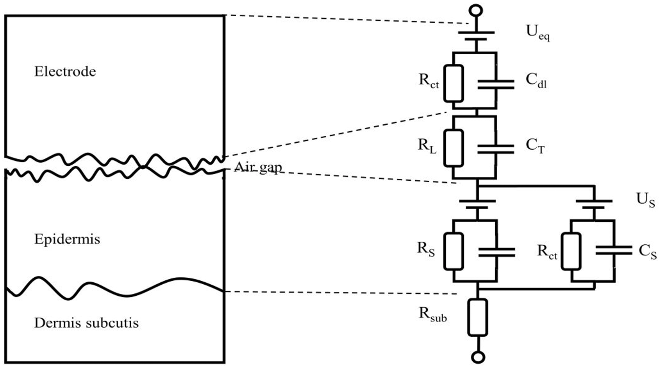
Theoretical electric circuit model of the skin-electrode interface of a dry textile electrode adapted from Beckmann et al. 21
Such an elaborate model is sometimes necessary to use, but at other times, it will suffice to consider only the dominating parts and hence reduce the complexity of the model. The main purpose of this text is to present an easy-to-use method for evaluating textile electrodes, not to evaluate the models. In the remainder of the text, in the case of wet commercial electrodes we will only consider a model with one time-constant and in the case of dry textile electrodes a model with two time-constants. The most dominating factors for our case will be the impedance of the epidermis and the
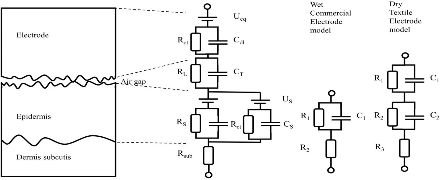
The most dominating factors for our purposes are the
The skin-electrode impedance depends on many factors and most of these factors stem from the properties of the skin. This puts some demands on the measurements and reporting of the characteristic of a candidate electrode. As the impedance will vary depending on where on the body it is placed, when in time measurements are taken, between different subjects and so on, using a phantom instead of in vivo measurements to evaluate the impedance can provide some information about the electrode's performance, but it may not always accurately reflect the performance on human skin. These matters have already been pointed out by Rosell et al.,
17
and also by McAdams,
29
hence we suggest, in line with the suggestions of both Rosell et al. and McAdams, that when reporting on the performance or characteristics of a potential electrode the impedance measurements should be done without any skin preparation, on several subjects and preferably at sites on the body relevant for the application. As the skin-electrode impedance will display both resistive and capacitive behavior, we suggest that when reporting the skin-electrode impedance either some parameter (
Measurements of impedance
The electrical impedance of a device (such as an electrode, a semiconductor or a piece of biological tissue) is the measure of how hard it is for a current to pass through this device given a certain voltage across it. This is stated formally in Ohms law for time varying signals:


From a purely circuit theoretical point of view, when making measurements of resistance or impedance one can utilize three basic configurations: two, three or four-lead measurement. First, the name ‘two-lead measurement’ means that there are two leads in direct contact with the sample one intends to measure, ‘three-lead measurement’ means that three leads are in direct contact with the sample, and ‘four-lead measurement’ means that four leads are in direct contact with the sample. In all these cases one still needs four leads, it is just that the ones that are not in direct contact with the sample are connected to the circuit elsewhere. The two-lead measurement will give as a result a value that includes all impedances between the voltage measuring points, the four-lead measurement will exclude the contact impedances totally and, depending on the geometrical positioning of the electrodes, a three-lead measurement can provide the exclusive value of a single contact interface. These three basic configurations are displayed graphically in Figure 4.
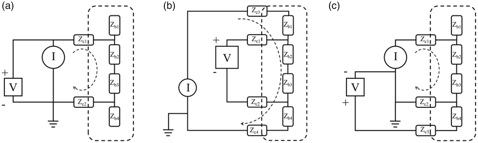
The three basic configurations for the measurement of impedance. The dashed line indicates the boundaries of the sample being measured. (a) In the two-lead measurement the value will include all impedances; (b) in the four-lead measurement only
In all three configurations, there is virtually no current running in the leads connecting the voltmeter to the circuit due to the voltmeter’s very high input impedance. In the two-lead measurement, the current passes all the impedances, and hence the result in this case will be:


If one is interested in measuring the impedance of some material, for example, human tissue, and wishes that the measurements will not include any contribution from contacts or cables then one can utilize the four-lead measurement. Looking at Figure 4(b) one can see that the voltage measured will not include the drop across

In Figure 4 the configuration of the leads shows that the voltage pickup electrodes are placed closest to
Now in the three-lead configuration we can see that the part of the sample,


What we have shown is that the three-lead configuration gives a measured value of the skin-electrode impedance which is a contact impedance. This configuration does not rely on any assumptions about symmetries or knowledge about the tissue impedance as they never enter the equation. The only assumption is that the input impedance of the voltmeter is high enough not to allow any current to leak into that branch. This assumption is met by all modern voltmeters. This configuration is the only one capable of actually measuring the contact impedance between the skin and the electrode. All other configurations will only make estimations of the contact impedance.
In vivo measurement of contact impedance
The in vivo measurement of the skin-electrode impedance is not a new possibility; it has been used within the biomedical engineering field for decades.17,31 However, as far as we could tell, within the research field of smart textiles, it has not yet been widely adopted. Some researchers have reported using a two-lead measurement,
13
but as shown above the use of this method will give the result for two contacts and the biological tissue between these contacts. When using the two-lead measurement, to say something about the contact impedance one needs to rely on assumptions of symmetries and of an accurate knowledge about the impedance of the tissue. Others have reported on successive two-lead measurements in which the impedance between the candidate electrode and two standard gelled electrodes and then again relying on symmetry calculating the skin-electrode impedance, although in this particular case the authors only reported the impedance value at a single frequency: 20 Hz.
20
Any method that relies on two-lead measurements will not actually measure the skin-electrode impedance but rather make an estimation based on assumptions of other parts of the system. As seen in equation (5), one needs to know the magnitude of tissue impedance (
In the text below, where we concentrate on the three-lead measurement we will refer to the contact impedances labelled
Methods
To show the validity of the method and to indicate the correctness of the experiments three types of tests were performed. In the first test dummy cells with known parameter values were used. In the second set of tests, commercial gelled electrodes were used. In the third set of tests, textrodes with (a) different sizes, (b) exposed to different pressures and (c) different sheet resistances were used. The same instrumentation was used for all tests. Below we start by describing this instrumentation and then we outline the details of the three sets of tests. We also describe the material properties of the textrodes used.
Measurement instrumentation
In principle, what is needed to perform a three-lead measurement is a signal generator and a device that can measure, at the same time, the current through the system and the voltage at two locations relative to signal ground. Here we will demonstrate the use of a multi-channel USB-oscilloscope with a built-in signal generator, PicoScope 5442 D MSO, and a laptop, all driven by batteries. A free third-party software for frequency response analysis, FRA4PicoScope by Aaron Hexamer,
32
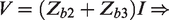
was used. An oscilloscope does not measure currents, so we used a shunting resistor with known resistance and measured the voltage across it. For convenience when measuring we built a simple front-end where one can change the value of the shunting resistor. The practical implementation is schematically shown in Figure 5, and a photograph of the set-up while measuring on a dummy cell is shown in Figure 6. The software FRA4PicoScope drives the device under test with a sinusoidal signal and sweeps the frequency between values determined by the user. The software then returns a matrix with the frequencies, the gain and the phase of the measured system. The gain is defined as:
Schematic diagram of the set-up. The oscilloscope provides the driving signal (blue line) and measures the voltages directly above and below the electrode under test (
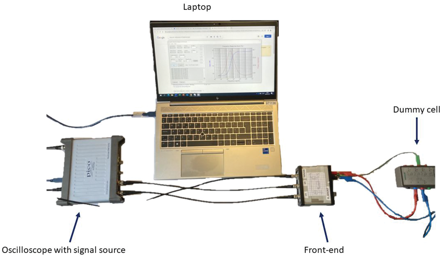
A photograph of the set-up while measuring on a dummy cell. The front-end is mainly constructed for ease of use and the shunting resistor can be changed if needed.
In our measurements
and

If we substitute these expressions into equation (8) we end up with:

Depending on the settings (number of points per decade, stimulus time, lowest frequency to be measured etc.), to get one spectrogram takes only a couple of minutes. For instance, the spectrograms reported below in this paper were set to take 10 points per decade, starting at 1 Hz and going to either 10 kHz or 100 kHz. Each measurement took about 2.5 minutes to complete.
Electrodes and textrodes
Measurement 1: dummy cells
To be sure that the method provides numerically correct estimations, three dummy cells made from discrete passive components (resistors and capacitors) were measured. Resistors and capacitors with 1% tolerance were used in the construction of these dummies. The result of the measurement on one of the cells is reported in the Results section below, the expression for the impedance of that cell is given by:

Measurement 2: commercial gelled electrodes
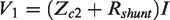
As a second test, four in vivo measurements on the supine forearm were conducted. The placement of the electrodes can be seen in Figure 7. In these measurements commercial gelled electrodes from Covidien were used. Before the tests two electrodes were connected with their gel sides facing each other and the electrode impedance was measured to be
The forearm with glued on commercial electrodes used to show the independence of symmetries when doing in vivo in three-lead measurements.
To show that the body impedance does not influence the measured value if one uses the proposed method, two-lead and three-lead measurements were conducted where the signal input was located at first at the foot and then the stomach. After that, a test where the auxiliary electrodes had different contact impedances towards the body was conducted to show that it does not matter. In one case the Ambu BlueSensor R electrode was used at the inlet of the signal at
Measurement 3: textrodes
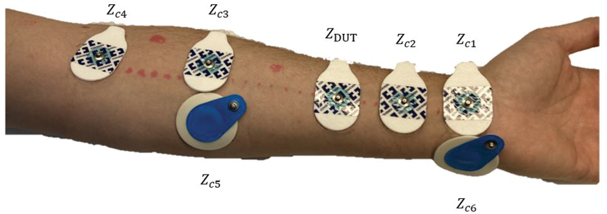
The two last tests were done with textrodes. One where the same type of commercial highly conductive fabric was used as a textrode. For this test, four different surface areas of the textrode were tested, a photograph of those textrodes can be seen in Figure 8(a). Finally, a test using three different textrodes as electrodes under test: one with a sheet resistance of
To the left textrode with four different surface areas. To the right three textrodes with very different sheet resistances. The areas of these three electrodes are equal.
Results
Measurements on dummy cell
The measurement of one dummy cell is displayed in Figure 9. The left panel shows the magnitude, and the right panel shows the phase angle. The scattered dots are the measured values, and the solid blue line is the theoretical curve. The topology of the dummy cell is also indicated in the figure.
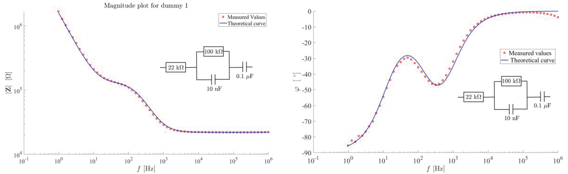
Results from measurement of a dummy cell. The left panel shows the magnitude of the impedance of a dummy cell. The right panel shows the phase angle of the impedance.
As can be seen in Figure 9, the measurements are in almost perfect match with the theoretical expression for the magnitude. There is a slight deviation between the theoretical and measured phase shift at some frequencies, most notably at the high frequency end of the spectrum.
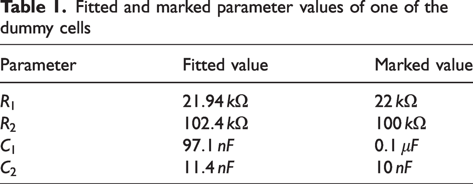
Using the measured magnitude and the expression in equation (10) in the curve fitting tool in Matlab, the fitted parameter values became as in Table 1.
Fitted and marked parameter values of one of the dummy cells
Measurements with commercial gelled electrodes
In the left panel of Figure 10, one can see the results of three consecutive measurements, the set-up is varied in three ways: first the current inlet electrode and the electrode where
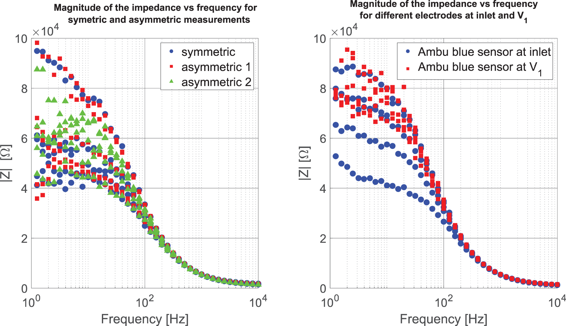
The resulting spectrograms of three measurements conducted on the supine side of the forearm.
The results of the comparative measurements using the two-lead and three-lead methods and having the inlet of the signal either at the foot or at the stomach can be seen in Figure 11. The two two-lead measurements include different amounts of body impedance most notably in the lower span of the spectrum. The three-lead method only measures the skin-electrode impedance.
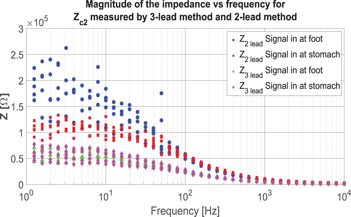
Results of two-lead and three-lead methods. Both two-lead measurements include different amounts of body impedance and two skin-electrode impedances, resulting in large differences at lower frequencies. The three-lead measurements only include the skin-electrode impedance.
Measurements on textrodes
The results of varying the size of the textrodes are displayed in Figure 12. The impedance increases with decreasing area over the whole frequency range. The impedance of the smaller sample with 4.84 cm2 presents the largest magnitude, which is between 10 and 13 times larger than the impedance measured for the sample with the larger area. The impedances for all four samples display a somewhat flat frequency response in the range
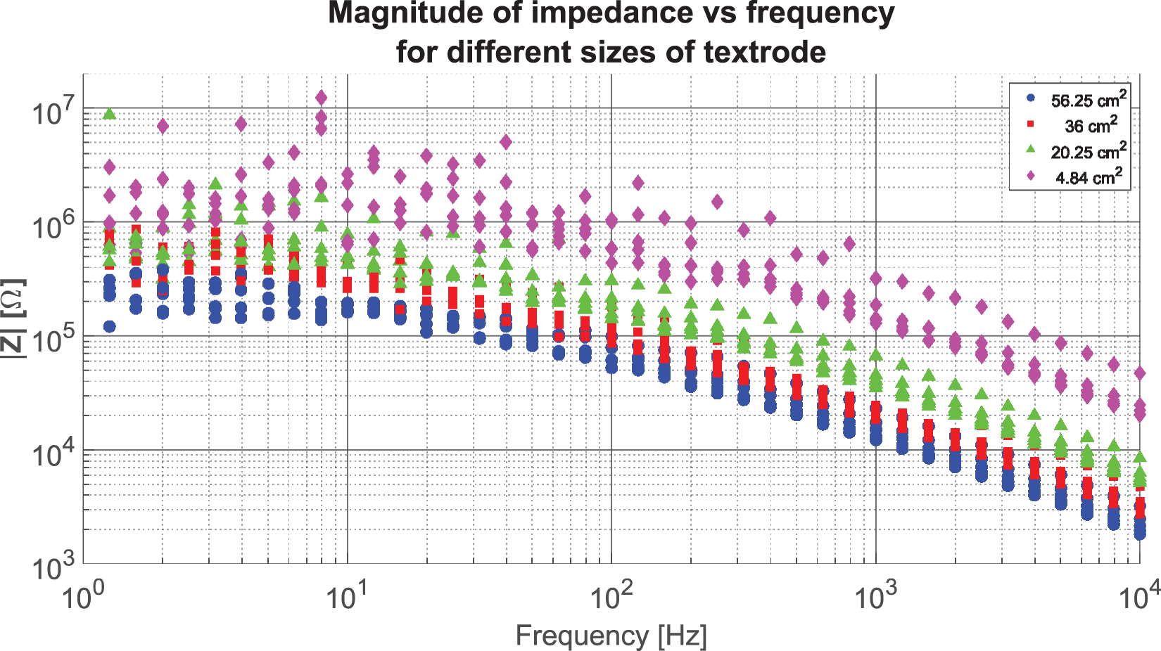
The magnitudes of the impedances of all four textrodes with different surface areas.
The magnitude plots in Figure 13 shows the results from the measurements done with three textrodes with very different sheet resistances. The general behavior of all four samples displays the same behavior as seen in Figure 12, a flat frequency response up until c. 10 Hz, whereafter a decline begins. The values for the textrode with the lowest sheet resistance, 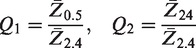
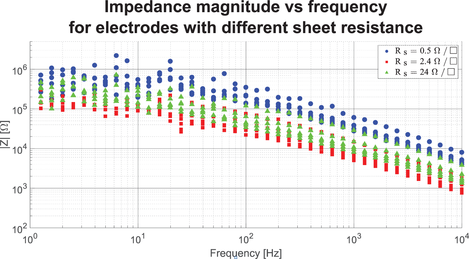
Magnitude plots of contact impedance between three textrodes and the supine forearm.
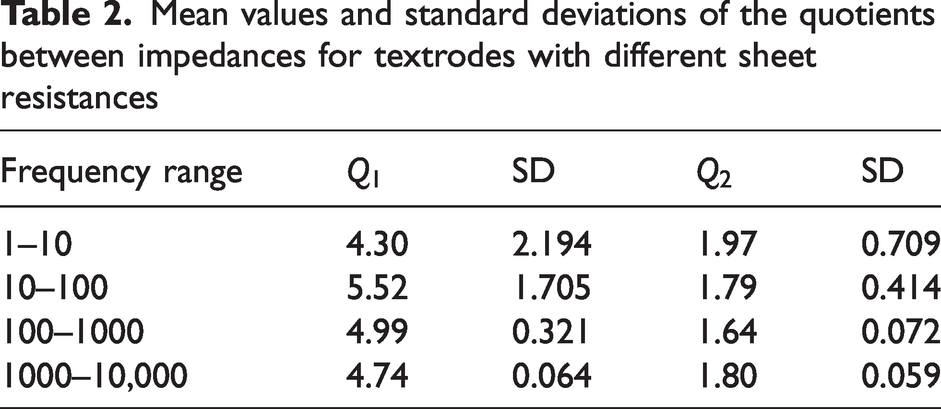
In Table 2 the mean values and standard deviations per decade can be seen.
Mean values and standard deviations of the quotients between impedances for textrodes with different sheet resistances
Discussion
In vivo versus in vitro measurements
As is evident from the results in Figures 10–13 even when doing consecutive measurements right after each other in a time span of 1 h on one subject without moving the electrode, the variability of the measured impedance is rather high especially in the low frequency part of the spectrum. This variability has much of its root in the physiology of the human skin. Thus, evaluating the usefulness of a candidate electrode in vivo will give useful information as opposed to measuring the gel-to-gel side of electrodes or to measure on a phantom or any in vitro standardized substrate. This is also pointed out by researchers in the biomedical research field.17,29 In essence measuring electrodes gel to gel is equivalent to measure an electrode to a phantom. What is being measured is the interface of the metal in the electrode and the oftentimes highly conductive gel or agar phantom. This is not equivalent to the situation when the electrode is interfacing the human skin. The variability of the impedance of the human skin depending on the site on the body and on the temporal conditions makes in vivo measurements far superior for evaluating a candidate electrode. For textrodes intended to work without the preparation of trained personnel, in a dry state with the stratum corneum of the human skin intact measurements must be done in vivo. The failing of characterizing the Z might mean the difference between a recording or stimulation working or not. The wrong characterization might mean energy wasting in the contact instead of the body. McAdams 29 has argued very convincingly that even though an organization such as the Association for the Advancement of Medical Instrumentation recommends evaluating ECG electrodes by measuring the gel-to gel impedance this is a test that will not predict the performance of the electrode, because what is being measured is the impedance between the metal and the gel of the electrode. He especially points out the case of poor correlation between this kind of measurement and the case of dry, cleaned skin. As we have mentioned earlier a long-term goal for the application of smart textiles intended for health monitoring is to have the textrodes working in a dry state with no skin preparation. This is an even more severe deviation from the abraded skin situation in which the correlation between gel-to-gel impedance and skin-electrode impedance was good. The same line of argument can also be seen in Eggins. 33 The author also recommends an in vivo three-lead set-up for evaluating the electrode performance.
Adequacy of the method
To begin with, from a theoretical point of view this is the only possible way of measuring a contact impedance. Our measurements also supports that this can be done in an easy and fast way. The machinery that we have used can be changed in accordance with the needs of the specific measurement one wishes to conduct. In our case the set-up is prone to parasitic capacitances at frequencies above c. 1 MHz. This tendency can be seen in the phase plot of Figure 9; there is a clear decrease in the phase angle commencing around 300 kHz and is clearly visible at 1 MHz. For our purposes that is not a problem because we mainly deal with biopotentials and stimulations in which the relevant high frequency limit never exceeds c. 10 kHz.14,34,35 The results in Figure 9 indicate that the set-up is capable of measuring accurately in frequency spans relevant for most biopotential and electrostimulation applications. The estimated values in Table 1 are all less than 5% off from the marked values except for
The three-lead in vivo method
Our results and the discussion in the two foregoing subsections all point to the rational conclusion that for characterization of textrodes one should conduct three-lead in vivo measurements. The implementation of this methodology that we have presented will provide realistic and useful numbers when designing and evaluating smart textile products. As previously mentioned, skin-electrode impedance measurements usually display rather large variability in the lower frequency regime. This is unfortunately also where the most information resides in the case of biopotentials. A large set of measurements needs to be conducted on a wide range of individuals, representing the variety of skin properties in a large population. This could provide some mean value of the impedance that one could use when dimensioning one’s measurement system. Although that mean impedance most often does not exist, or rather only a small part of the total population has it. As an alternative to that approach, one could instead go for a ‘worst-case scenario’. If the system is intended to work on healthy adults in the age range of 25–50 years doing athletics, then one performs the measurements on a small set of subjects in that category. Most probably one will not encounter any problems at all in that case because sweating will establish a good contact and the impedance will be low. If the target group is elderly people not performing intensive activities, the contact will be dry and poor. In this case, one should concentrate the characterization on the worst case (highest impedance) and design one’s smart textile product according to that case.
The results displayed in the left panel of Figure 10 show that with the proposed method one does not need to rely on any assumptions of symmetry of the measurement set-up, as long as the channel measuring
Sheet resistance
The results of Mestrovic et al.
1
indicate that there is no overall correlation between either low yarn linear resistance nor fabric resistance on the one hand and low skin-electrode impedance on the other, hence the measurement of linear resistance or sheet resistance will not suffice to make the proper choice of material when fabricating textrodes. Likewise, as seen in Xiao et al.,
20
by looking at their Figure 5(d) and Table 4, there is no correlation between sheet resistance and skin-electrode impedance. This is also seen by our results in this text. Figure 13 shows that the textrode with the lowest sheet resistance,
Summary discussion
We have argued that the most important aspect when designing textile electrodes intended for use as surface electrodes on the human body is the contact impedance between the electrode and the skin. Furthermore, we have argued that measurements of such contact impedances should be done in vivo. We have also demonstrated a straightforward method for conducting such in vivo measurements whereby we also showed in one case that there is no correlation between sheet resistance and contact impedance. The demonstrated method does not depend on any assumptions of symmetry or any accurate knowledge of the tissue impedance. The method is not uncommon in the field of bioimpedance research, and we are convinced that the smart textile field will benefit from taking it into use. The reasoning leading up to equation (7) and the spectrograms in Figure 10 and Figure 13 indicates that the proposed method does not depend on any geometrical symmetry of applying the electrodes nor on the values of the contact impedances of the auxiliary electrodes. From the magnitude plots in Figure 13 one can see that there is no correlation between the magnitude of the sheet resistance of an electrode and the contact impedance between said electrode and the human body, hence the reporting of sheet resistance having very little bearing on the feasibility for making a good electrode from a given candidate material.
Conclusions
In order to measure skin-electrode impedance, in vivo measurements are preferred as the impedance is mainly determined by the properties of the living skin itself. Impedance values measured between textrodes and phantoms, or simulated human skin, may provide initial information, but cannot accurately reflect the situation on real human skin. The sheet resistance is not enough to determine whether a textrode will result in a low skin-electrode impedance because there are clearly cases where no correlation between the two quantities exist. The three-lead in vivo method is a low-cost, easy-to-use, fast, and accurate way of evaluating textile biopotential electrodes. This method does not rely on any assumptions about the equality of contacts or the symmetry of the tissue because these factors are not included in the impedance calculation. Overall, in vivo measurements are preferred for accurate evaluation of skin-electrode impedance, and the three-lead in vivo method is a useful tool for evaluating textile biopotential electrodes due to its simplicity, accuracy, and ability to avoid assumptions about the tissue properties. Therefore, this method has the potential to improve the research and development of smart textiles for healthcare, leading to more efficient and effective smart textile sensing systems.
Footnotes
Author’s Note
Fernando Seoane is now affiliated with Department of Textile Technology, University of Borås, Borås, Sweden; Department of Clinical Science, Intervention and Technology, Karolinska Institutet, Stockholm, Sweden; Department of Medical Technology, Karolinska University Hospital, Stockholm, Sweden and Department of Clinical Physiology, Karolinska University Hospital, Stockholm, Sweden.
Declaration of conflicting interests
The author(s) declared no potential conflicts of interest with respect to the research, authorship, and/or publication of this article.
Funding
The author(s) received no financial support for the research, authorship, and/or publication of this article.