
Abstract
The pattern changes on the 3D rotary braiding machines (maypole principle with horn gears with full and empty slots) require complex planning of the carrier positions and timing and allow for production of bifurcated and other complex braids with variable cross sections for medical and technical applications. Another common application of pattern changes is to make a visually different pattern for marking of the remaining length of rope when used in a climbing context or for generally lengthened pieces for medical sutures. The development of such samples has previously been done using the trial-and-error method. This paper presents one rule for supporting a more systematic and purposeful trial, which significantly speeds up the development process. After a short review of the related literature, the main theoretical background is given and two practical cases for pattern change are demonstrated. The patterns were developed using numerical simulation before being tested on a real braiding machine. With this paper the authors hope to give some motivation for the remaining braiders in the world to continue working on the development of systematic rules for this complex process.
Braided products are used worldwide, but often remain a mystery to the consumer. For example, between 1500 and 1800 meters of braided fabrics are integrated into each car in the form of heat, electrical, and noise insulation and protection of cables, remaining hidden to the drivers. 1 Each mobile phone has a fine braided antenna. 2 These products, as well as most ropes, wires, and hoses, are regular linear products with a constant cross section. However, in some applications, braids with a changing cross section, or generally speaking with pattern changes, are required. For the climbing industry it is important to know the remaining length in one rope, so producers change the color of the material along the rope to indicate the length. Changes of color affect costs but do not have the color fastness against friction. For this reason, the rope producers change the color pattern at these positions so that the friction with the stones does not remove the color of the colored spinning filaments. In order to change the pattern, special machines with computer-controlled switches and more gears are required. This paper offers a method for the selection of the suitable tracks and switch states for the transition between two patterns. The paper concentrates on the process-based conditions for successful pattern transition for machines with any configuration, including continuously rotating horn gears, where one carrier from one horn gear is transferred onto the empty slot of another horn gear. The rules are verified using software for numerical simulation of the braiding process and two samples are tested on a real braiding machine with 4 × 4 horn gears.
State of the art
Terminological clarification
This work is dedicated to the related methods of braiding machines with continuously rotating horn gears. The authors introduce here the wording “continuously rotating horn gears” for the machines with horn gears which can rotate continuously, where one carrier from one horn gear can be transferred onto the empty slot of another horn gear only if the corresponding empty slot is available. This principle was named as the “maypole braiding principle”, 4 because the carrier relative motion around one horn gear is the same as in the maypole dance. The same motion is available with lace braiding machines as well,5–7 and in this “the maypole” is not correctly assigned to only one class of machines. Many authors use “rotary braiding machines” in this case,8–11 where in reality, the term “rotary braiding” can be assigned as well on the lace principle because the gear plates are rotating there too. 12 A very clear difference between these principles is the continuity of the motion – the commonly used braiding machines with horn gears and full and empty slots has continuously rotating horn gears and the lace technology-based machines have clearly discontinuous motion of the gear plates, which alternate between stopping and rotating. This paper concentrates only on the machines which have continuously rotating horn gears, which in the remaining text will be named only braiding machines, except if explicitly referenced.
State of the machine development
The most commonly used braiding machines work with a constant pattern and produce ropes, laces, covered cables, antennas, and other technical products.1,4,13,14 In addition to these machines with standard tubular and flat cross sections, several more complex configurations for braiding of products with a complex cross section are described. The patent of Akiyama et al. 15 describes machines for building double-T profiles. Tempel et al. 16 propose a machine with continuously rotating horn gears for braids with multiple interlacement of the single layers. Uozomi et al. 17 present machines, built as a combination of several partial track pairs for tubular braiding, which interconnect at several places. Brookstein et al. 18 patented blocks of tracks, which can be combined in order to build machines for complex profiles. All these machines were designed based on the track pattern, but it is unlikely that the carrier occupations are checked in these patented configurations. Additionally, they have fixed tracks and belong to machines used for the braiding of products with a constant (complex) cross section.
True 3D braiding started with the programmable switches,4,19 where the program for the splitting of flat braids into two flat braids was provided on punch cards. This principle was applied on larger machines with individual drives for horn gears and switches. An example of this is the machine with 12 × 12 horn gears developed in cooperation between Herzog GmbH and ITA, RTWH Aachen. 20 A smaller variant of the same machine with a set of 4x4 gears (named the VF-variational braider) has been found in recent years in several laboratories and educational institutions as it offers the option for braiding more than 15 braiding forms with constant geometry, 4 as well as various configurations with changes of the switches. A 3D braiding machine with a larger number of gears is reported in Guowei et al. 11 and two-time bifurcated braids are demonstrated. In the latest research on machine development, Du et al. 8 investigate the optimal design of the gears for such machines, which allow a continuous process. Improvement of the carriers for the reduction of fluctuations in carbon fiber tension is reported in Hu et al. 21 , 22 The mathematical modeling of the friction between yarns is reported by Zhang et al. 23 All these works demonstrate that 3D braiding with continuously rotating horn gears has reached maturity as a technology and equipment and increases its application areas.
Planning of the pattern and machine control
The 3D braiding machine requires a program for the control of the gears and switches. In this area only few solutions are reported. For the pattern development and control of the 12 × 12 machine of Herzog, special software “CAB Run” was developed. 24 , 25 It allows simulation of the carrier motion with changes in the switches during the braiding process. This software seems to be based on a rectangular arrangement of the gears only and its implementation works on the basis of a fixed matrix with the positions of the carriers. 26 Although it allows simulation of the process, the user has to perform a large number of “trials and errors” until one specific 3D configuration becomes defined. There are no recent reports about the state of this software. One matrix-based method for the state of the carriers and tracks is reported in the recent work of Guowei et al. 11 They propose classification of commonly used minimum splice tracks as “484” type, ∞ type, 2 × 2 oblique type, and V type, and represent the larger 3D track as an integration of such subparts. Although the splicing procedure does not seem to fit the equivalent tracks and the matrix representation remains unintuitive, this work provides a good background for future development of the mathematical theory of 3D braiding.
A different approach is followed by the team of Kyosev and their Computer Controlled Braiding Machine Configurator (CCBMC) software, distributed through TexMind.27–29 In this software the horn gears, carriers, and switches are implemented as objects and the carrier motion is predicted based on a computational model, where the forward motion of the carriers depends on the position of the horn gear and the position of the switch.30,31 The graphical user interface allows for stepping of the motion of the carriers and in this way provides a simulative tool for large sets of “virtual trials and errors”. Based on this software, a theory concerning the consideration of a set of horn gears as an extended horn gear is developed and tested in order to obtain the type of the structure, defined by its floating length. 32
With the exception of this systematic investigation and the rules for the arranging carriers, the authors did not find any other published research about the principle rules for preparation of sequences for the production of 3D braids.
The published works for row-column braiding 33 cannot be applied to braiding machines with continuous rotating horn gears, and the latest matrix method 11 needs some additional development in order to become useful for the planning of transition between two patterns. This work presents a novel idea for the description of the process, based on the position of the carriers in the future. It introduces “carrier delay” as a term for the time that one carrier has to spend before coming to a position in a new track in the transition between two constant patterns.
In the next section, the relationship between carrier arrangement and floating length will be explained. This is followed by a section representing the problem description, a section on the new proposed methodology that is applied for pattern changes in tubular structures, and another section for braids with bifurcations.
Carrier arrangement and floating length
One of the main tasks in programming a braiding machine is the avoidance of carrier collisions. This principle of braiding assumes that one carrier, position A, moves on one gear and is transferred to an empty carrier, position B, of another gear (Figure 1).
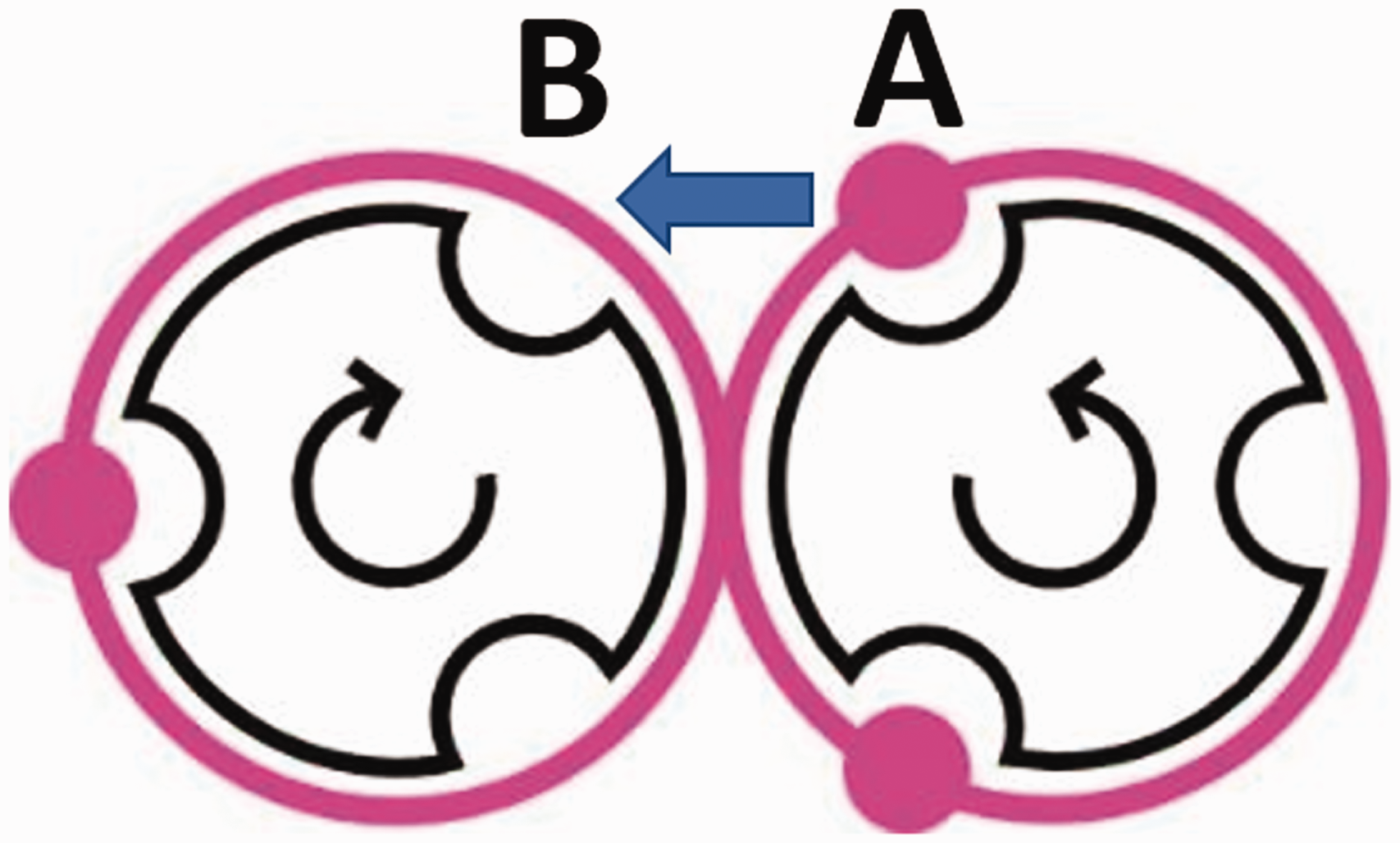
Two horn gears with three slots each and a carrier arrangement of one full, one empty. The carrier from slot A has to be transferred to the empty slot B.
This can be arranged for standard braids on machines with four slots following several rules, described in most braiding books, beginning with the books of Lepperhoff
19
and later works.
13
,
14
,
34
The latest detailed explanation is given in Kyosev,
4
where the relationship between the pattern type and the machine configuration is demonstrated. Depending on the number of slots on a horn gear, different carrier arrangements can be set. The carrier arrangement defines the crossing repetition of carriers between two horn gears, which determine the floating length of the yarns transported by the carrier. Figure 1 shows the horn gear and carrier set up for a classical flat braid with three carriers. Following the carrier track, it is recognizable that the horn gear slots are engaged in a “one full, one empty”:


Following the equation for the relationship between the gear size and repeat of the carriers,
4
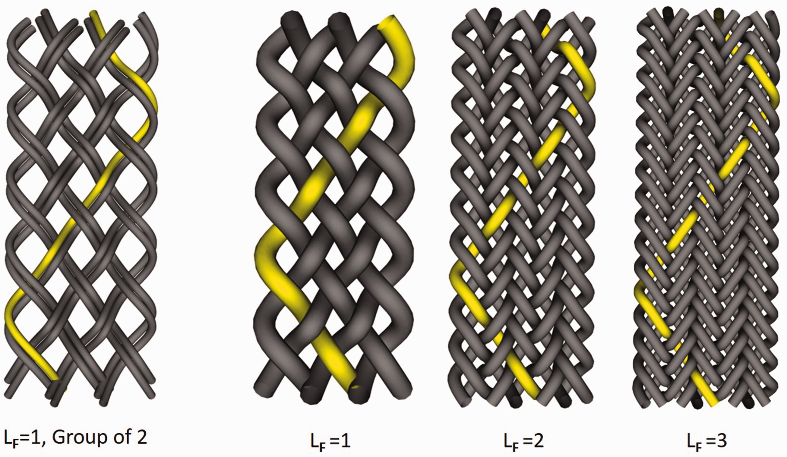
the floating length, LF, of a single yarn as a whole number of the ratio between the number of slots on one horn gear, NSlots, and the repeat of the carrier arrangement, Rca, is:
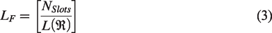
The floating length determines the interlacement and thus the pattern type. Figure 2(b) presents braided structures with a floating length of one, Figure 2(c) with a floating length of two, and Figure 2(d) with a floating length of three. Following from equation (3) for the floating length of three gears, six slots will be required. Another parameter which determines the pattern is the arrangement of the carriers within the same length of the occupation. For instance, if two carriers are running one after another and two empty positions are kept, then the repeating unit will have a length of four:

Braiding interlacement types with different floating length (LF) and yarns in a group.
Problem description
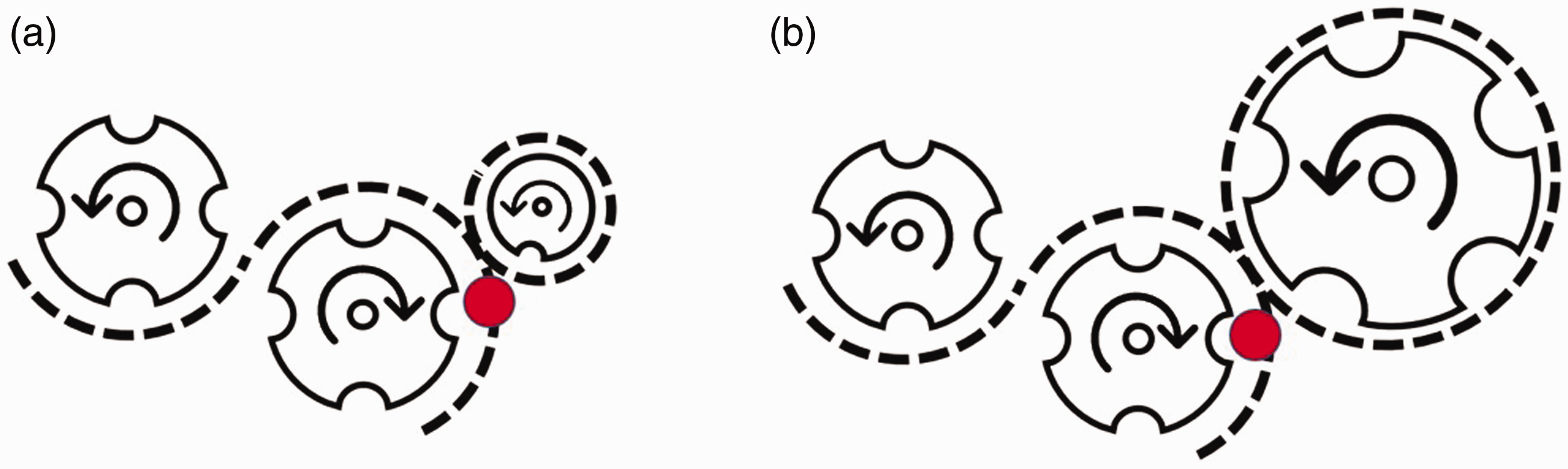
Through our understanding of the theoretical background of braiding patterns, it is logical that a change in the floating length is only possible by influencing the carrier arrangement. In addition to the carrier occupation, if a switch state changes, the track can change as well (Figure 3). This causes the carrier to follow a path with another configuration and length leading to a change in configuration.
Changed track: (a) original situation; (b) extended track after changing the switch state.
The task can be formulated in the following way:
Given is a braiding machine, which can work with different carrier arrangements and switch states (machine configurations) A and B. Each configuration can be used for the production of different types (color or structural pattern) of braids.
To be found: Possible arrangements of the carriers and switches (and from these, the resulting tracks) in order for a transition of all carriers from configuration A to configuration B to be done (Figure 4).
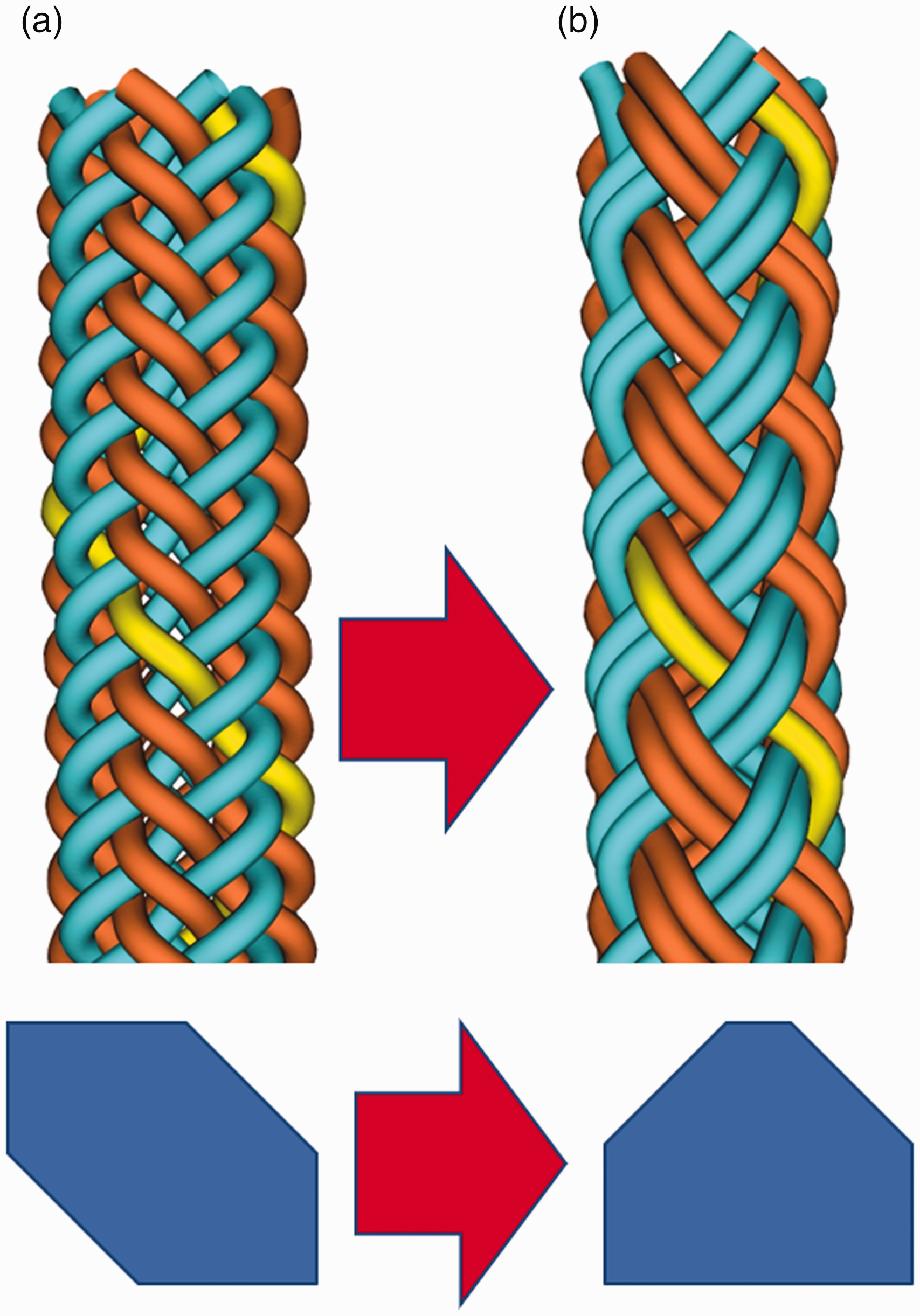
Task definition: Find carrier configuration for changing the pattern from (a) to (b). The polygons are graphical representations of the change, where the parts of the initial polygon have to be moved to other positions.
If this transition process has to be implemented on a braiding machine, this has to be rearranged from configuration A with carrier arrangement
Machine configurations for patterns (a) and (b) from Figure 4.
Of course, this task cannot be performed on normal tubular braiding machines as presented in Figure 5 because both the tracks and temporary positions of the carriers for this transition are missing. For such a solution, additional gears outside or inside the gear cycle have to be placed, as these are available in some core-sheet machines. This is only meant to clearly demonstrate what the initial and end state must be. In order for this transfer to become possible, additional tracks (ways) for the carriers and horn gears have to be made available.
Methodology
Figure 6 visualizes the required transition process for changing from one pattern to another in an idealized symbolic way. The task is to define the transition between configuration (a) and configuration (e). The yellow triangle (Figure 6(b)) represents one carrier, which has to leave its current place, run through some tracks for a specific time (Figure 6(c)) without causing collisions, and occupy a new position (Figure 6(d)) at the appropriate moment. This can be achieved with the second carrier on the track, or the third possible position (here marked with red and bold)
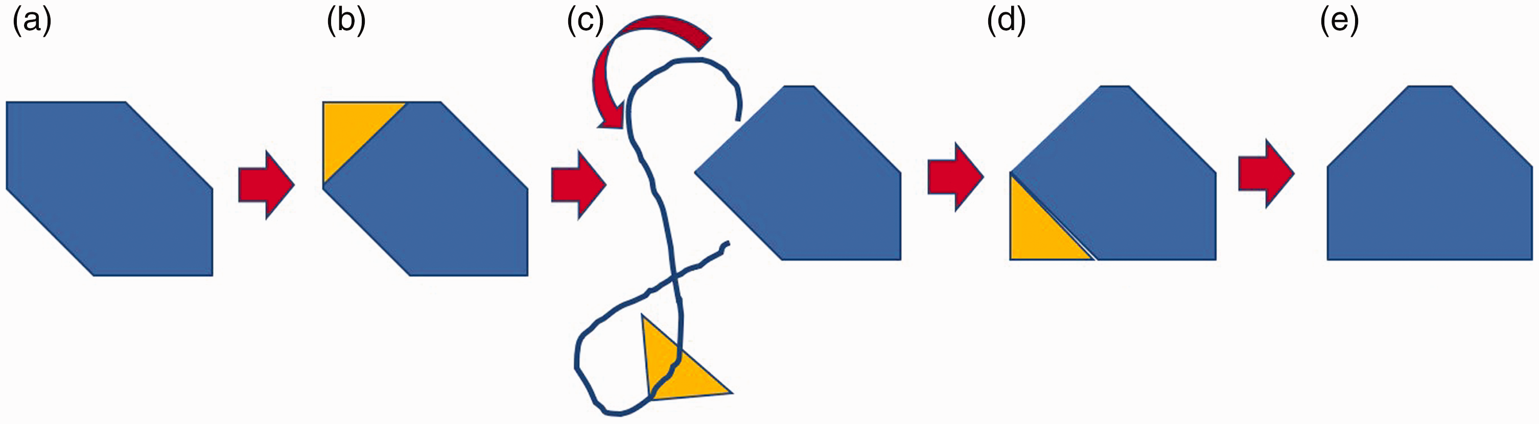
Idealized graphical representation of the transition process from one pattern to another.
This workflow can be described as follows;
Obtain the final state of the braid in the old pattern Identify which carriers in the arrangement could be moved to achieve the new pattern Change switch states to send these carriers to travel around the machine for a certain time so that, at the correct moment, the next step can be completed At the proper moment, change the switch configuration and include from the outside track the carrier back into its new position Close/change the transfer switch so that they do not disturb the motion of remaining carriers.
Something that is not well specified in this workflow is “how long is the certain time” in which the carrier has to look around. This task requires some more systematic analysis.
Figure 7 demonstrates the position of the carriers with triangles in the initial (old) and the end (new) configurations. The empty slots are represented by thin rectangles. Ultimately, the carrier at the wrong position has to move one slot back, meaning one slot is delayed in its movement.
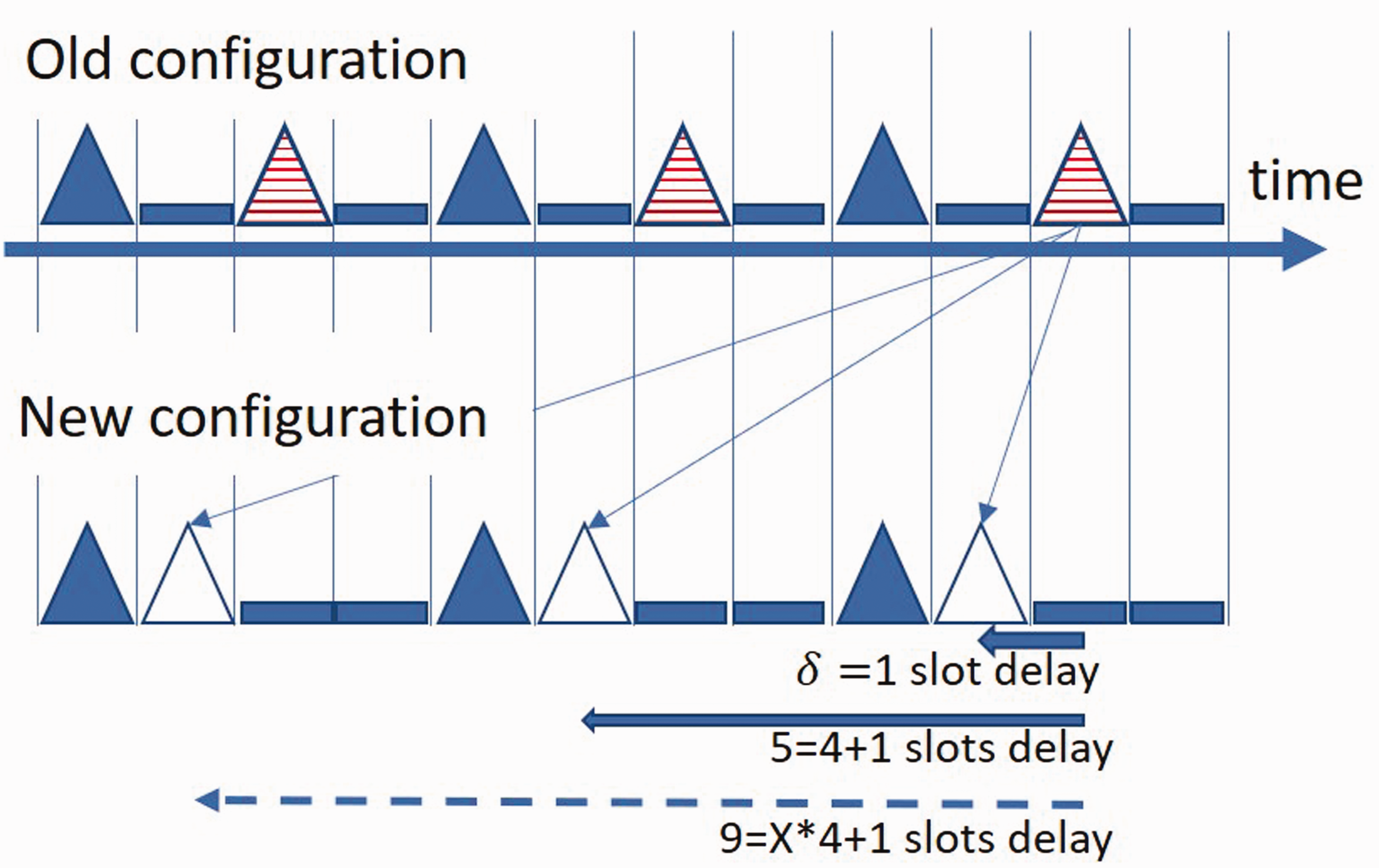
Old configuration and new configuration of the carriers over time for computing the carrier delay.
The technical solution for implementation of a one slot delay can be done in several ways;
Use of horn gear with one slot only (Figure 8(a)). This additional gear takes the carrier and moves it around and gives it back to another gear after one slot duration time. An advantage of this solution is that it supports the good dynamics of the process: the horn gear can rotate with the same speed as the others. There may be problems with this approach if the size of the gear is too small to accommodate the complete slot geometry.
Some technical possibilities for implementation of delays. Use an additional gear with any number of slots, but with controllable velocity. This is calculated so that the received carrier is moved around and given back after the time of one slot. This solution is technically possible with modern motors, but causes impact forces, accelerations, and requires very precise electronics. It is not clear if this performs in production state and remains stable over long periods of time. Use a gear with five slots (Figure 8(b)) or (x * 4 + 1) slots, which rotates synchronous in the system and delivers the carrier in some of the positions in the next groups. (Here x is any number larger than one, but in practice gears with larger number slots for x = 2, 3 etc. require a lot of space, and are not used.)
Here the equation for the delays is:

In reality, if only a machine with 4 × 4 horn gears is available, none of these solutions can be applied directly. The only solution is the application of the theory of the extended horn gears, 32 where the path of the carrier is generated as a composite curve around several gears. For the current case, it will mean that for the carrier, which has to be moved, a path has to be found with a length of 5, 9, or (x * 4 – 1) slots. Once the path is found, the suitable switches must be activated so that the carrier takes this one.
Of course, during all these steps, it has to be considered that no one carrier collides with others.
Application of the theory
Pattern change for braid with eight yarns
The following example of a variation loop shows an eight-carrier square braid with a “two full, two empty” carrier arrangement,

Moving forward cannot be applied on machines where all gears are running simultaneously. For this reason, the carrier has to be moved virtually forward to one slot and then delayed one complete cycle (of four slots) backward, which means that the required delay is three slots:

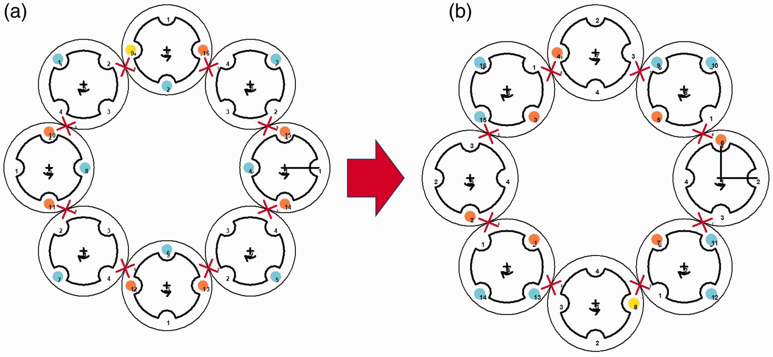
For implementation of this change for an eight carriers/yarns braid, the initial and end states have to be placed in the middle of the 4 × 4 horn gears machine. Of these eight carriers, half have to be moved to a new position, so the operation has to be applied four times and all 16 horn gears of the variation braider with 4 × 4 gears are used. The solution on the machine is not just “straight forward”, but requires 15 single states, or iterations, until the transition happens. During this transition, for each of the carriers the delay of

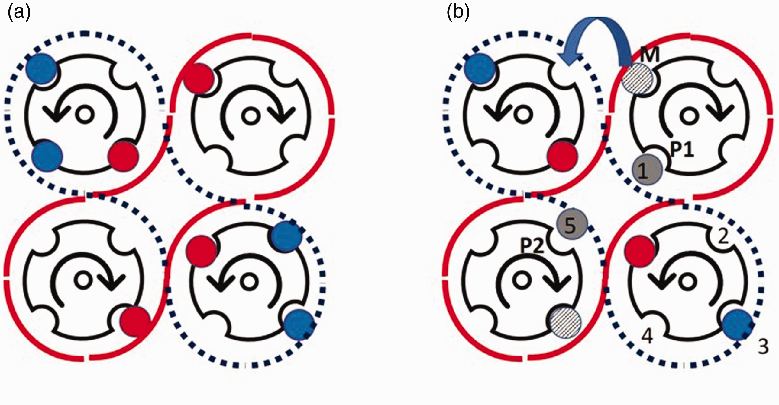
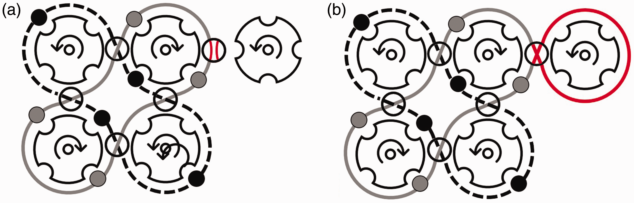
Counting the delay in case of pattern change: (a) original configuration (b) counting where carrier M has to be moved in order to get the new required position in another track.
For the case of moving the wrong carrier to another track, the carrier M runs at the original configuration (Figure 9(a)) but has to be moved to another track to position P1 or P2 (Figure 9(b)). Counting the slot position from its potential new position, if it is moved to another track, it has to delay the
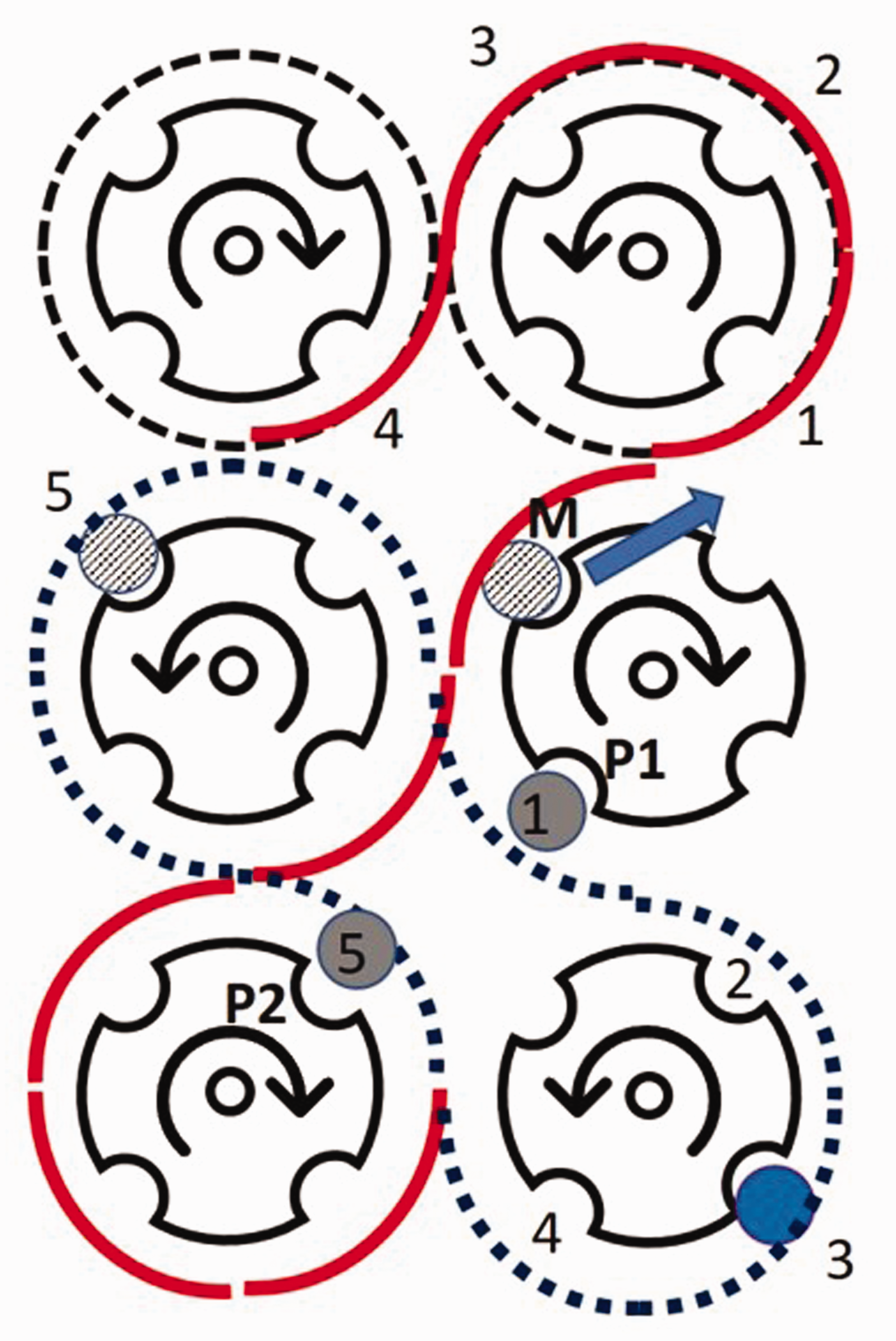
Possible path of the carrier M to become delayed on five slots.
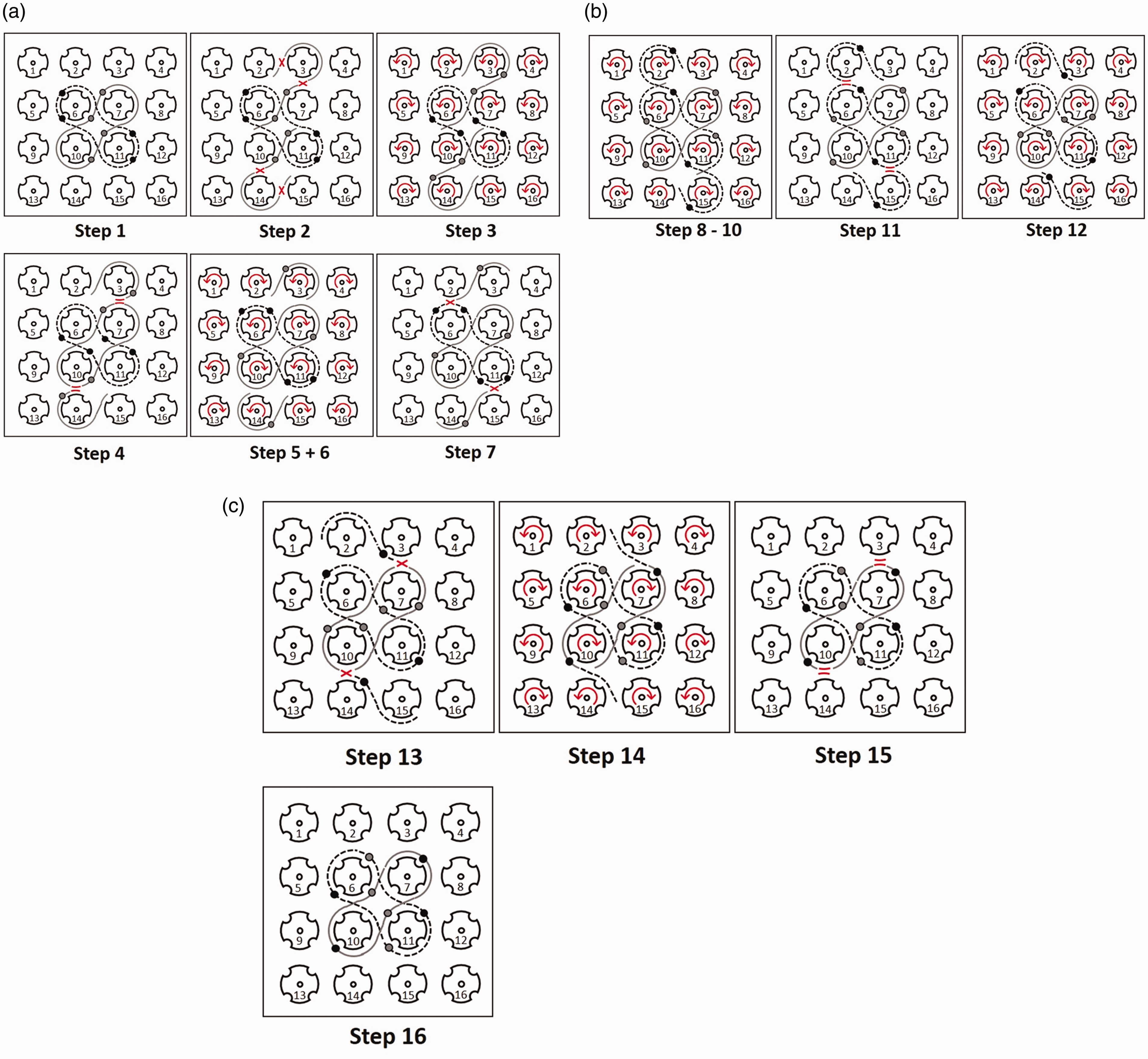
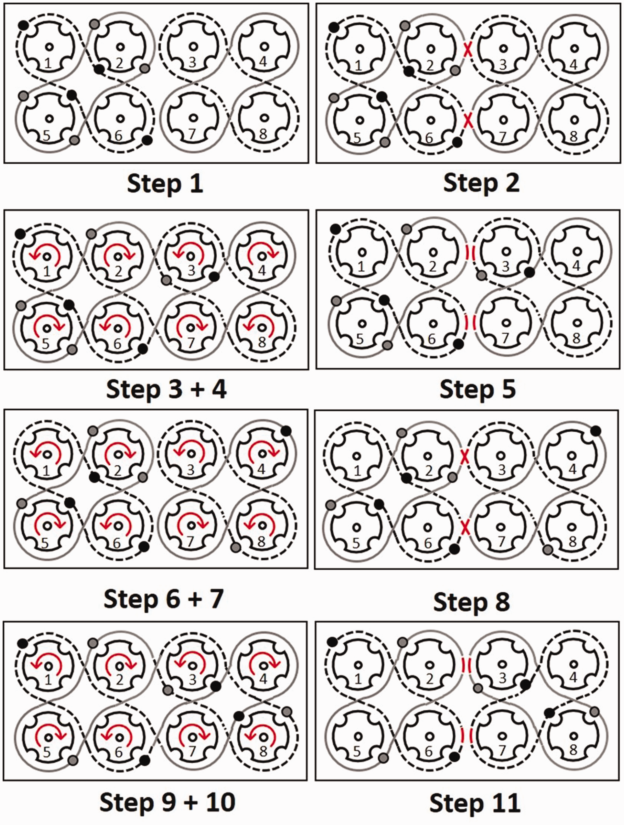
Complete sequence for change of an eight-carrier square braid with LF = 1 to LF = 2 on a variation braider.
The complete program requires the moments on which the transfer switches are set back, so that the carrier with the correct place does not start to move with this on the wrong place. The algorithm is tested using the simulation software TexMind CCBMC 27 and implemented on the VF machine from Herzog (Figure 11); the practical braid demonstrates that the pattern change worked as designed.
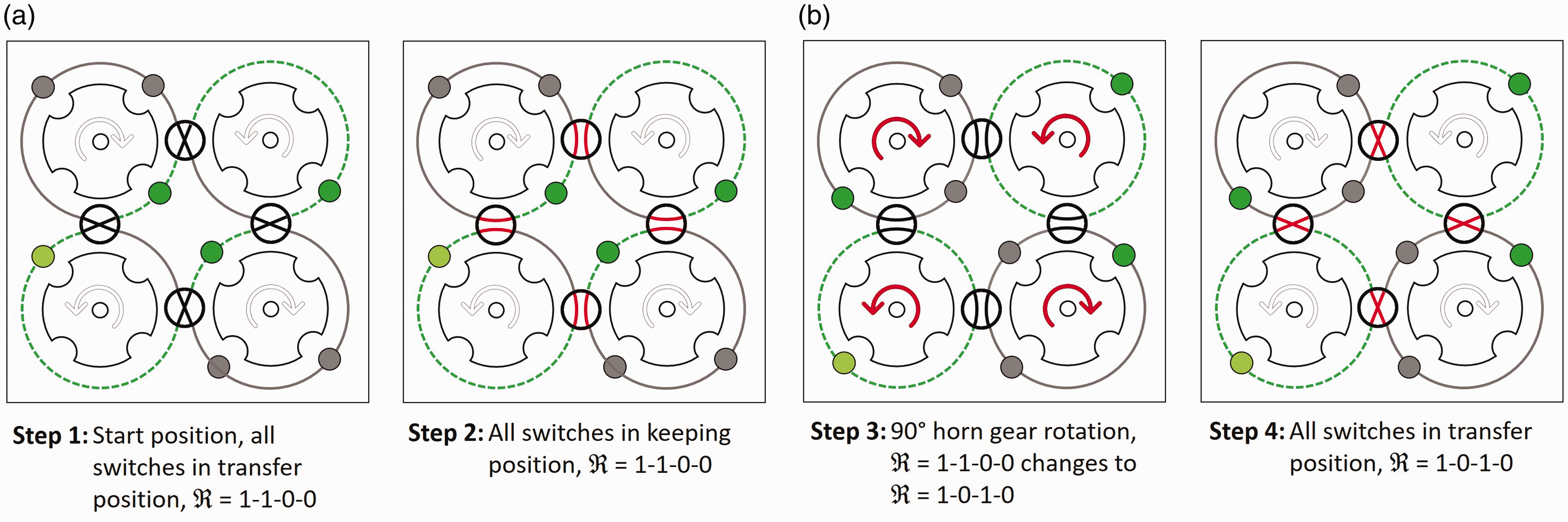
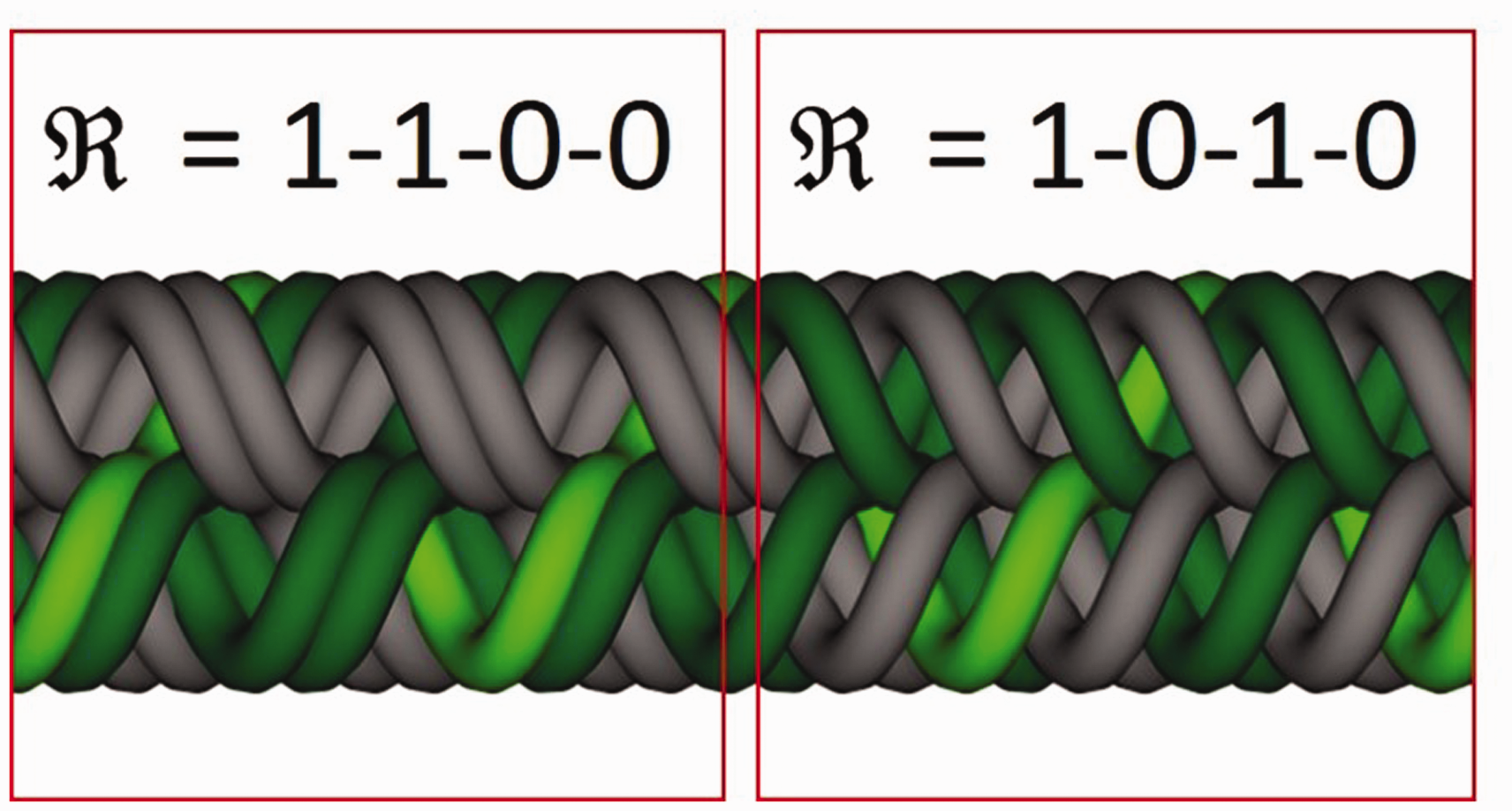
The process of creating a variation loop is complex, so the steps in Figure 12 are explained in detail now.
Step 1 is the start position. There is a
Once these two carriers are placed on a new track for the delay, the switches between horn gears 3 and 7 and 10 and 14 are set to the keeping position again in Step 4. This is necessary because otherwise the following carrier
After that, Steps 8 to 10 are used for moving the carriers for three slots. With this process two carriers of the second track are leaving their regular track. Here it is noteworthy that, in this case, the behind moving carriers (
In Step 11 the switches between horn gears 2 and 6 and 11 and 15 are set to the keeping position. Now, the second track (shown dotted in Figure 9) has a
There are at least 15 steps necessary to change the pattern from
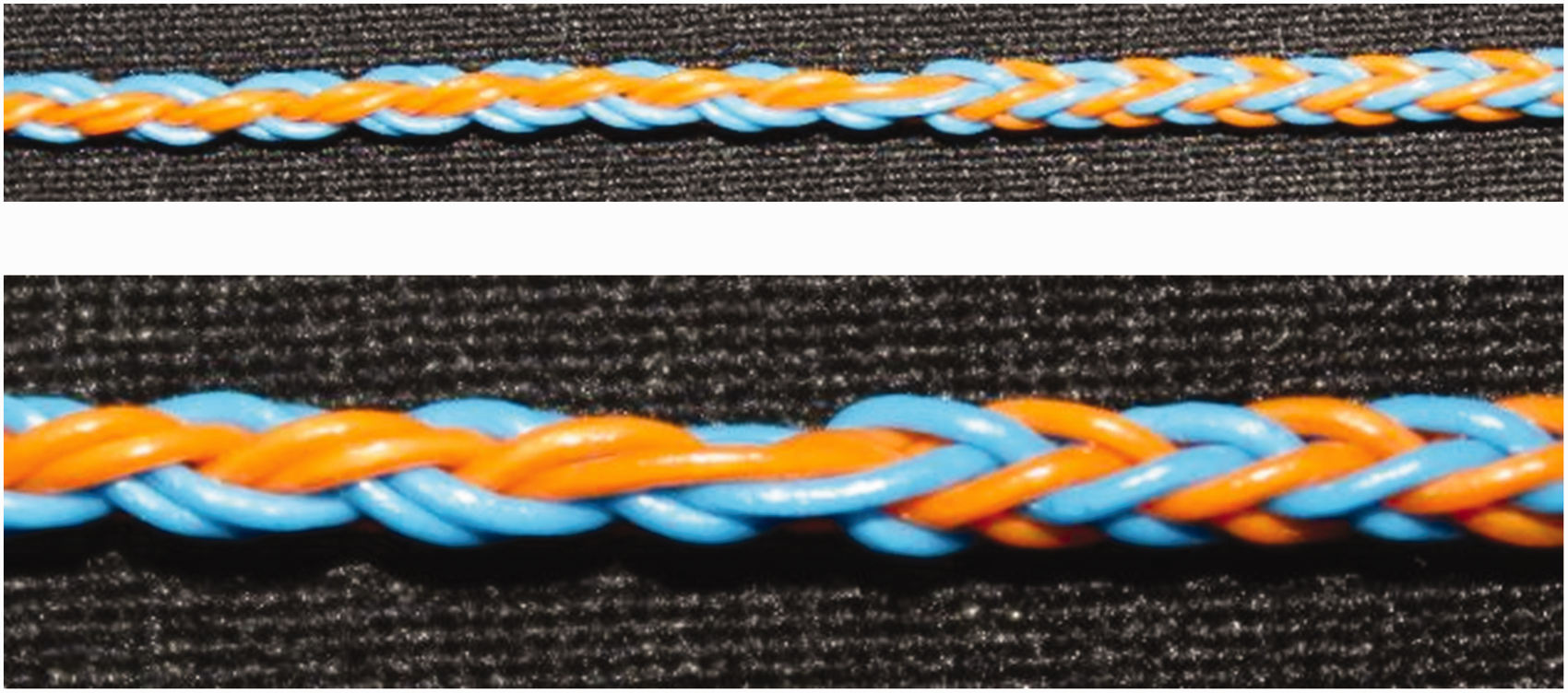
Braided example of a pattern change from LF = 1 to LF = 2.
Observing the pattern change in Figure 12, a transition between the two patterns is noticeable; there are larger straight yarn pieces between the two patterned parts. This disturbance happens because of the use of additional horn gears for the delay. This longer visual piece in the transition can be reduced if the take-off of the machine runs some pieces backward before starting the transition in order to get the yarn relaxed, and then after the finishing of the transition starts running forward again.
Shorter way for pattern change for braid with eight yarns
After several trials to find the above rule for calculating the delays and path trials, and its description and application for the sample of a braid with eight yarns, during the phase of the final formatting of the manuscript an alternative, shorter way was found for the same pattern change. Figure 13 demonstrates this sequence with single steps, generated by the simulation software TexMind CCBMC.
Shorter way for change of an eight-carrier square braid with LF = 1 to LF = 2 on a variation braider without using horn gears for a delay.
In Step 1 the starting carrier arrangement is
In this situation a simpler change procedure was found, which is faster and does not cause longer yarn pieces in the transition zone. This was possible only because the authors were aware of the current theory, of the required delay, and then determined at which configuration this can be possible. The simulated idealized 3D braid based on the carrier motion is visualized in Figure 14, where the pattern change is also proven by numerical simulation.
Simulated braid of the variation loop in Figure 13.
Application of the method for planning bifurcations
In the case of bifurcations and other profiles, the same approach can be applied. In this more general case, the carrier arrangement for the complete track at the initial state and for the new state have to be written. Let, for example, a bifurcation from an eight-yarn braid to two braids with four yarns be created. The motion of the carriers in one track at the initial braid is based on a carrier configuration with arrangement “one full, one empty” (1-0), extended here four times because some of the carriers will then be removed:

The new carrier arrangement with only half of the carriers has to represent a “one full, three empty” arrangement:

The two removed carriers have to go to another track and run in the same configuration. As the opposite track needs the empty positions, the carriers, which have to be removed, have to remain in the same track, so the delay in this case is zero
Variation loop for a bifurcation including a pattern change.
For this variation loop, 11 steps are necessary. It starts with a carrier arrangement,
In Step 2 the switches between the horn gears 2 and 3 and 6 and 7 are set to the transfer position. Following a carrier movement of two slots in Steps 3 and 4, two carriers from both independent tracks leave their regular track. Now the changed switches from Step 2 are set to the keeping position again in Step 5. There are four independent tracks with a carrier arrangement
After the carriers are moved for two slots in Steps 9 and 10, and the switches are set back to the keeping position in Step 11, the bifurcation with the pattern change is done. The results are two independent braids with a

This pattern change becomes clearer when observing the produced braided example in Figure 16.
Bifurcated braid including pattern change: left = eight-carrier square braid with LF = 2; right = two four-carrier square braids with LF = 1.
Conclusions
This paper presents a new rule for the computation of the timely delay of the carriers, which must be introduced for the transition from one pattern with a given carrier arrangement to another pattern with a different carrier arrangement to be performed. This rule supports the development of track configurations, still using the “trial and error” method, but is performed with numerical simulation software. As a next step for the future, this rule can be implemented in software for automatic checking of suitable paths for transitions between two patterns. This can be utilized in both methods, as reported by the researchers: numerical simulation of the process with software and in the matrix methods.
Footnotes
Declaration of conflicting interests
The author(s) declared no potential conflicts of interest with respect to the research, authorship, and/or publication of this article.
Funding
The author(s) received no financial support for the research, authorship, and/or publication of this article.