
Abstract
This work presents newly discovered possibilities for producing lace-type patterns on typical 3D braiding machines with continuously rotating horn gears. Using specially developed 3D software for the simulation of the braiding process, numerical simulation of multistate braiding processes to obtain braiding programs as a set of switch states, led to the production of a lace-type interlacement. Basic knowledge about building braided pillow laces was first analyzed with the software and after that verified and produced on a 3D maypole braiding machine with a 4 × 4 set of horn gears and computer-controllable switches. The advantage of lace-type structures compared to classical flat-, round-, or square-braided patterns is the possibility to control the motion area of the carrier and set one particular thread to interlace only with a selected set of threads. This effect and this pattern advancement could be used for the development and production of samples with customized mechanical properties, mixing the effects of classical braids with lace-type braids.
The digital era has enabled use of modern software such as CAD programs for creating more complex textile structures, and has opened new application fields in industries as varied as automotive, medical, and lightweight construction industries. Due to the development of fibers, chemical treatments, and high-tech machines, modern textiles can supersede existing materials by providing better properties for various applications.%1 For example, using braided structures in the medical sector is now common: the braided stent for the treatment and prevention of coronary problems is the most common braided product.%2,%3 With modern braiding machines, like the variation braided machine employed in this study, the production of bifurcated braids (Y- or T-stents) used to reduce the effort when treating bifurcated arterials and veins%4 is possible by steering the switching between each pair of horn gears. Many of these stents are produced by braiding, as this allows placement of wires or filaments in suitable orientations within the structures. However, using braiding machines for the development of structures with different than standard interlacement can complex and resource intensive.
Numerical simulation of the braiding process was applied in this study with the goal of producing a lace-type braid on a 3D braiding machine (hereafter referred to as 3DBM) with continuous rotating horn gears and programmable switches. Compared to a typical tubular braiding machine, this braiding machine has the potential for wider applications, as it combines certain advantages of lace and braiding techniques. The computer-controlled, steerable switches can be programmed in multiple steps to allow production a variety of 3D structures for medical, composite, or smart products.
Figure 1 shows the variation braider, VF 1/4-32-140 (Herzog GmbH) employed in this research. It has 16 horn gears in a square 4 × 4 arrangement. The main difference between this and the classical square braid machine is the possibility to control each switch independently between every pair of horn gears. This allows changing the carrier track with one tap of the touch panel. The switches have two states: transfer and keep. Figure 2(a) shows the machine bed and in Figure 2(b) the horn gear and switch arrangement are shown. When the switches are set, the machine can produce an average speed of between 10 and 100 m/h. The horn gear velocity at 330 U/min is comparable to that of the classical round or flat braiding machines. The main difference with the variation braider is that when changing, for example, the braid cross-section by changing the carrier path, the production speed is reduced until the new carrier and switch state are achieved.
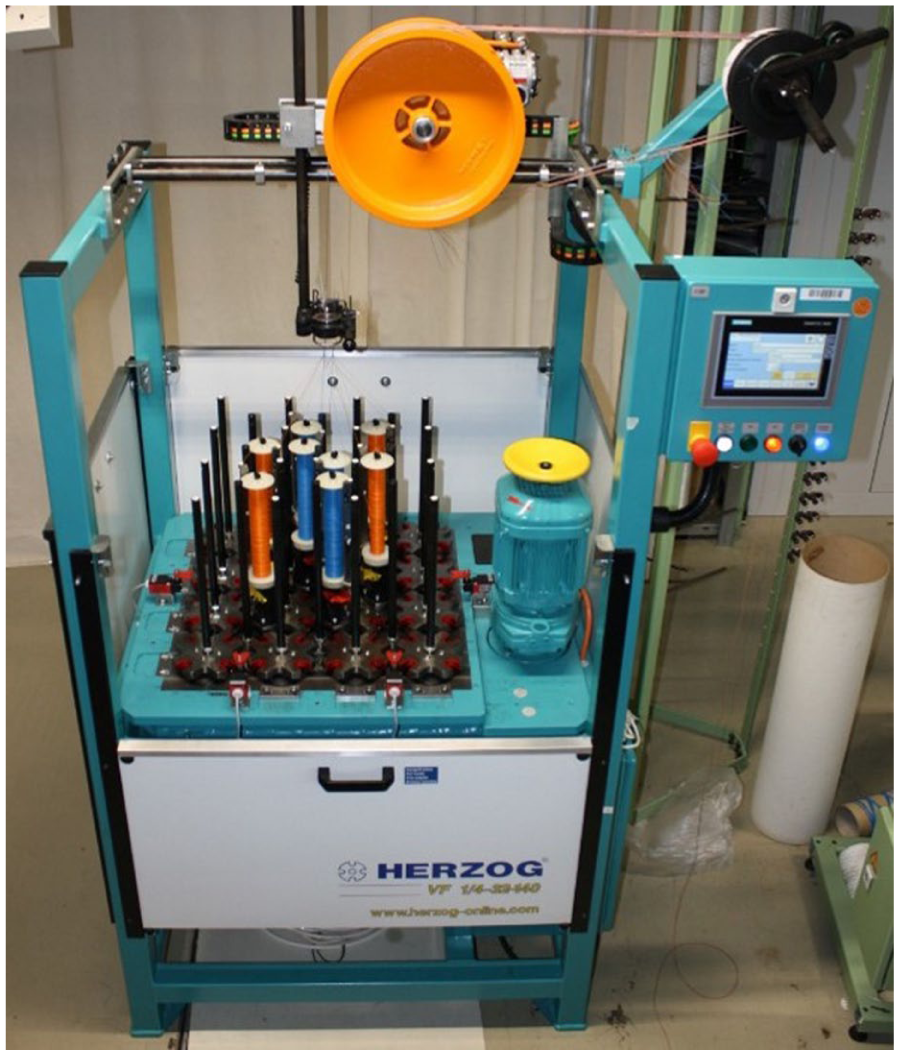
Variation braider VF 1/4-32-140 (Herzog GmbH).
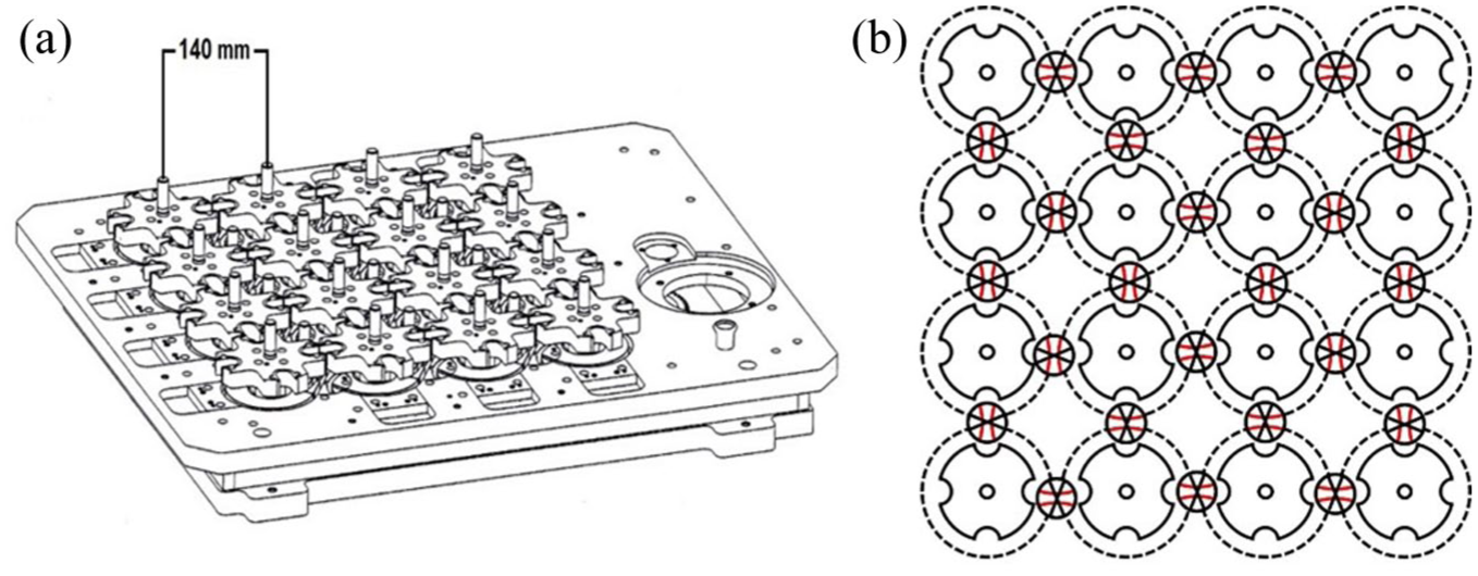
(a) Machine bed and (b) sketch of the horn gear and switch arrangement.
The creation of a lace braid on such a machine is novel, as this has not been reported in contemporary literature. Due to the complexity of the braiding process, the development of lace braiding on a variation braider is only possible using specialized CAD software.
A typical lace structure might be represented by the lattice structure of a fence. However, the remarkable patterns possible in lace structures are reflected in the individual, independent interaction of the yarns, which is only possible when every gear can be controlled independently. The machines for lace structures differ in that point from classical “maypole” (or rotary) braiding machines. While maypole braiding machines have continuously rotating horn gears, the lace braiders can rotate each individual horn gear independently and in specially arranged steps. Producing lace braids on classical maypole braiders is therefore not possible. The modern 3DBMs solve this problem and therefore enable new capabilities. Their products can be used in medical applications like stents or synthetic tendons, veins, and arteries. Another application is in the field of smart textiles that incorporate conductive threads.%1,%5,%6 The additional options for more flexible positioning interlacement places between selected yarns at various positions can be a big advantage of this technique, because it enables more design freedom and options for placment of conductive yarns in braided products.
After a short overview of the state of the art in lace and partial 3D braiding, this article introduces the braiding sequence for producing lace-type interlacements step by step, using a specialized CAD program. The computer software patterns developed were programmed on the real machine and verified experimentally in the production of real samples. Finally, some considerations for pattern development and productivity are given.
State of the art
Lace, commonly known for its use in tablecloths, decorative ribbons, and delicate fabrics, typically comprises a textile structure with a high number of embellished patterns (Figure 3). These textiles were originally made by hand, the first known examples of which date back to the fifteenth century.%7
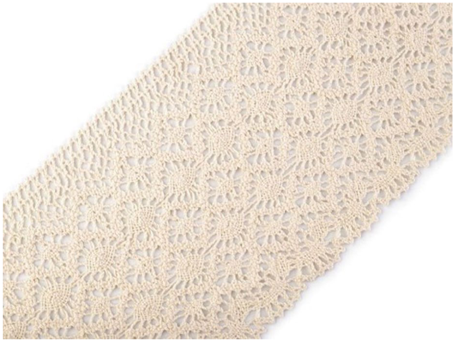
Example of braided pillow lace.%8
Lace originally could be differentiated as being one of two types: needle or bobbin lace.%9 With industrialization and modern technologies, handmade lace was replaced by machine-manufactured lace; however, it is still made by hand today as a craft activity. Various lace machines use different principles when building textile structures, such as the Raschel machine with its warp knitting principle, or the Barmen machine that constructs lace using the braiding principle.%9 The current study focuses on braiding.
An overview of the evolution of lace braiding machines can be found in David Branscomb et al.’s research,%10 where the Barmen lace machine is also mentioned. Classical maypole braiding machines provide two different yarn carrier tracks, where one track runs clockwise and the other one counterclockwise (Figure 4). These tracks are fixed and cannot be changed during production.
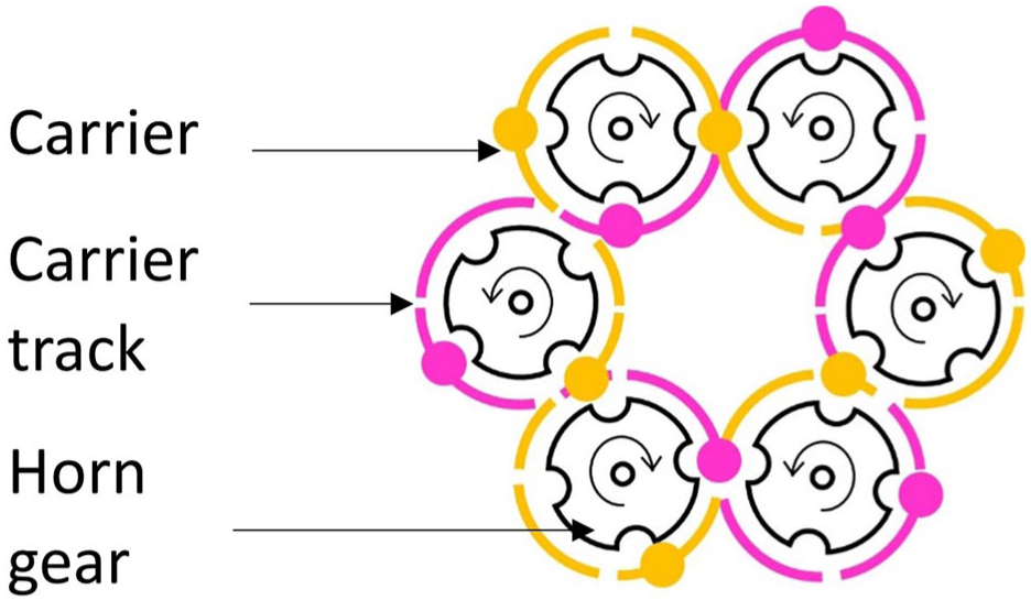
Horn gear set up and carrier paths of a classical 12 carrier maypole braiding machine.
The first technical principles of lace braiding machines can be found in patents like that of Krenzler back in 1909 and in the years that followed.%11–%13 The main difference compared to classical maypole braiding machines is that the carrier tracks and therefore the direction of movement can be changed with every step and in nearly every position on its track. Kyosev’s study describes this process and covers other differences to classical maypole braiding machines.%14 The main difference between maypole and lace braiding, therefore, is the ability to rotate particular horn gears independently from the surrounding ones during lace braiding.
Figure 5 illustrates the operating principle of lace braiding. Due to a 180° rotation of two horn gears, the carriers change their positions. At this point, a yarn interlacement of four yarns in two different columns leads to two independent twines. Now, a single horn gear rotation in the middle connects the two independent twines—another interlacement is achieved, and the lace structure is built.
Lace braiding principle with independent rotating horn gears.
Recent publications%10,%15 describe application of the principles of lace braiding technology in creating 3D braided structures for a huge array of future applications.
At this point, maypole braiding as well as hexagonal technology must be mentioned as novel braiding processes for creating 3D structures. One of the first 3D rotary braiding machines was invented by Tsuzuki et al. in 1989,%16 where a set of horn gears in a square arrangement transferred carriers stepwise from one horn gear to another. However, between every pair of horn gears, only one carrier could find a place, which reduced the yarn density in the braided structure as well as the pattern possibilities. Following an invention by Bogdanovich in 2002,%17 two carriers could find places between a pair of horn gears. His invention, working stepwise, increased the yarn density as well as the pattern possibilities.
In hexagonal braiding technology, one of the latest developments, reported by Schreiber,%18,%19 saw six carriers placed on each gear. The carriers are placed at 60° intervals around the horn gear—an arrangement inspired by honeycomb to reconstruct the closest packing of objects found in nature. With a device based on the work described in Bogdanovich’s publication,%17 two carriers could be placed between two horn gears and the maximum number of carriers increased significantly. Application of hexagonal braids has been investigated in the medical sector, for example, for use in stents or for replicating the human cruciate ligament.%18
The current research reports on a new possibility for producing lace-type braids on a 3DBM with continuous rotating horn gears. With Berger’s 1975 invention, steerable switches between two horn gears were introduced.%20 These switches enable the carriers to change their tracks, which, as already mentioned, was not possible before prior to this invention. There are several forms of 3DBM, the most widely distributed in recent years has 16 horn gears, arranged in a 4 × 4 matrix (Figure 6), and between every pair of horn gears, a steerable, computer-controlled switch is placed.%14,%17,%21
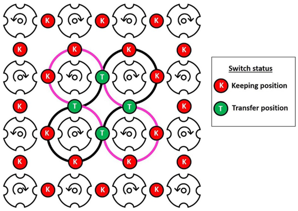
3DBM with computer-controlled, steerable switches between every pair of horn gears.
The 3DBM enables a huge variety of patterns and structural possibilities. In addition to classical packing braids with diagonal carrier paths, round braids, multilayers, and many more structures can be braided (Figure 7).
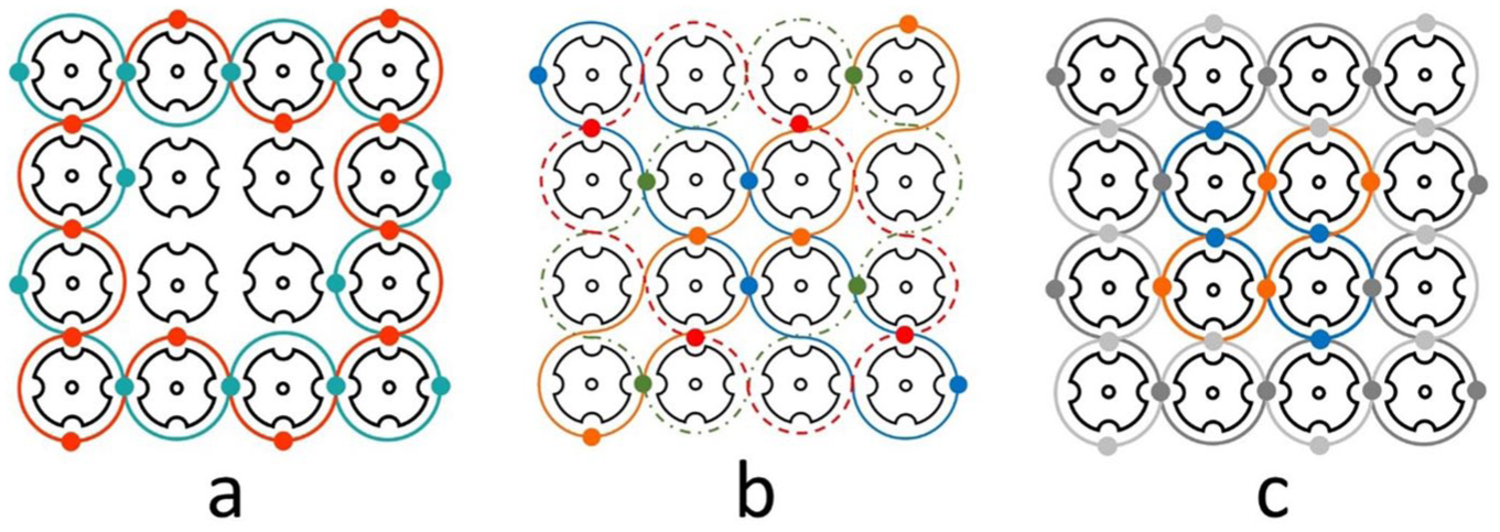
Different braiding possibilities on a variation braider: (a) 24 carrier round braid, (b) 16 carrier four-diagonal packing braid, and (c) two-layer core braid.
The continuous braiding principle is separated into steps, each of which can involve a 90° horn gear rotation, or a switch position can be changed. With this advantage many more structures can be braided, such as bifurcations or pattern changes. The steps to achieve this can be saved and reproduced by the machine if the program is accurately organized.%17 Since the programming of such variation loops can cause carrier damage due to collisions, use of CAD software to plan every step is mandatory.%22 Several CAD programs are available, for example CabRun (Herzog) and TexMind’s Computer Controlled Braiding Configurator.%23 –%25
Research on the application of variation braiders for lace structures is limited. Only one published work in this direction was found%26; however, careful reading of this paper showed that it covered the bifurcation technique as a combination of knots, similar to earlier studies.%27,%28 Recently, theoretical developments in the patterning of 3DBMs have been reported,%29 where the combination of multiple gears into one larger gear—that is, an extended horn gear—is described. The same authors subsequently theorized on the required carrier delay to reach a desired position.%30 This principle was applied in an intuitive way in the current research, and could be used for the development of clearer, mathematically based methods of lace-type structures in the future. Although the aforementioned papers refer to the same type of machine, examples of the production of real lace-type braids on a non-lace-type machine were not found in the literature.
The following section introduces an extension to the simulation software, which was performed to allow the development of such machines. Following this, the basic elements and theory for building lace-type braids are described. Development of the computer controls for three examples and their practical verification on real machine are reported.
Basics of lace braiding on 3DBMs
Lace braiding consists of two types of interlacement, depending on which direction the yarns are crossing. In the literature,%14 these are often referred to as “twisting” and “crossing,” but in reality, both types are actually only “crossing” but in a Z or S direction, depending on the visible orientation of the yarn. Figure 8 represents two carriers on a classical 3DBM (not on a lace machine), which is constructing an S-type crossing. If this path continues, at the next gear they will cross in a Z-type configuration.
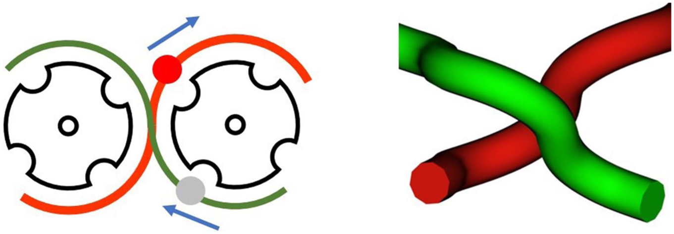
Realization of S-crossing yarns on a 3DBM.
Not typical of classical rotary or maypole braiding, here the 3DBM twists the yarns. For this type of interlacement, the carriers must already be on the same horn gear, all switches must be in the “keep” position, and after each complete rotation of the horn gear one actual twist will be given (Figure 9).
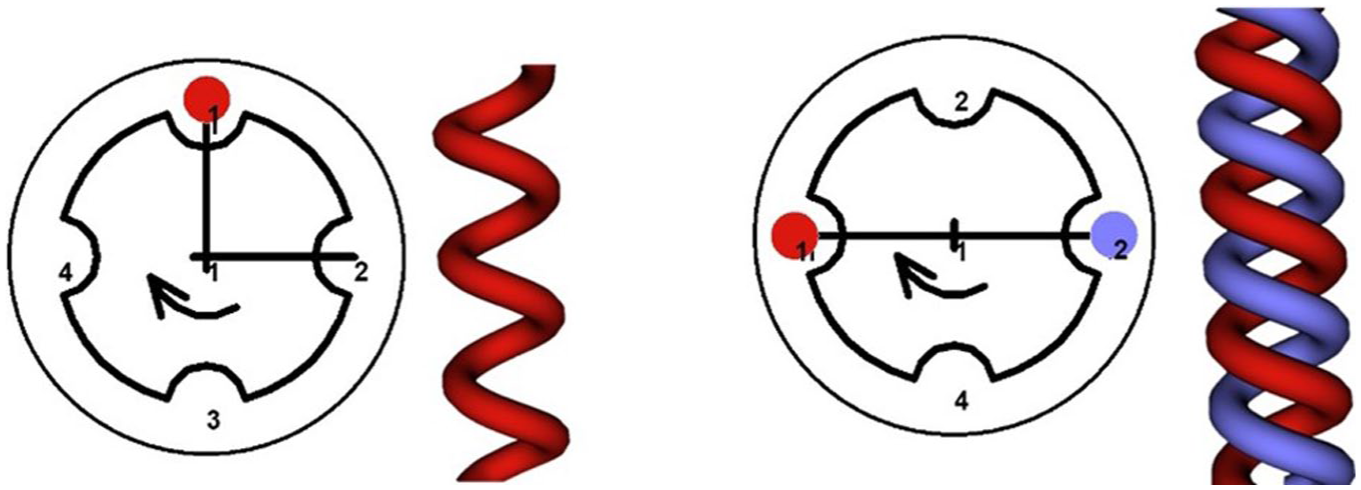
Twisting principle: if two carriers rotate around the same gear, they will construct a twisted structure. No transfer to the next gear is allowed.
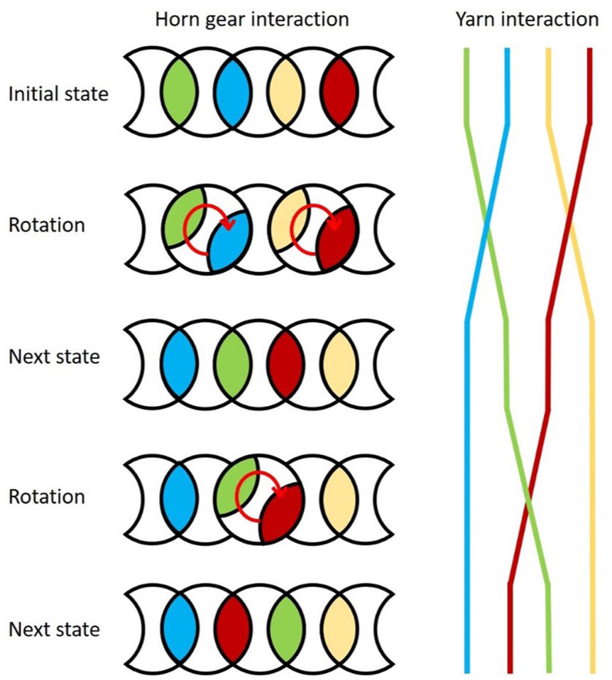
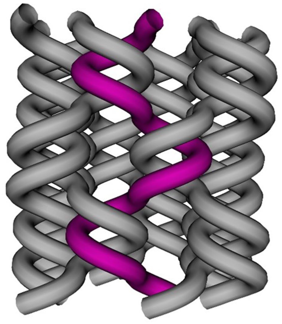
This capability provides the “building blocks” for lace, as each lace consists of a combination of crossing in one or the other direction, with twisted elements (Figure 10).
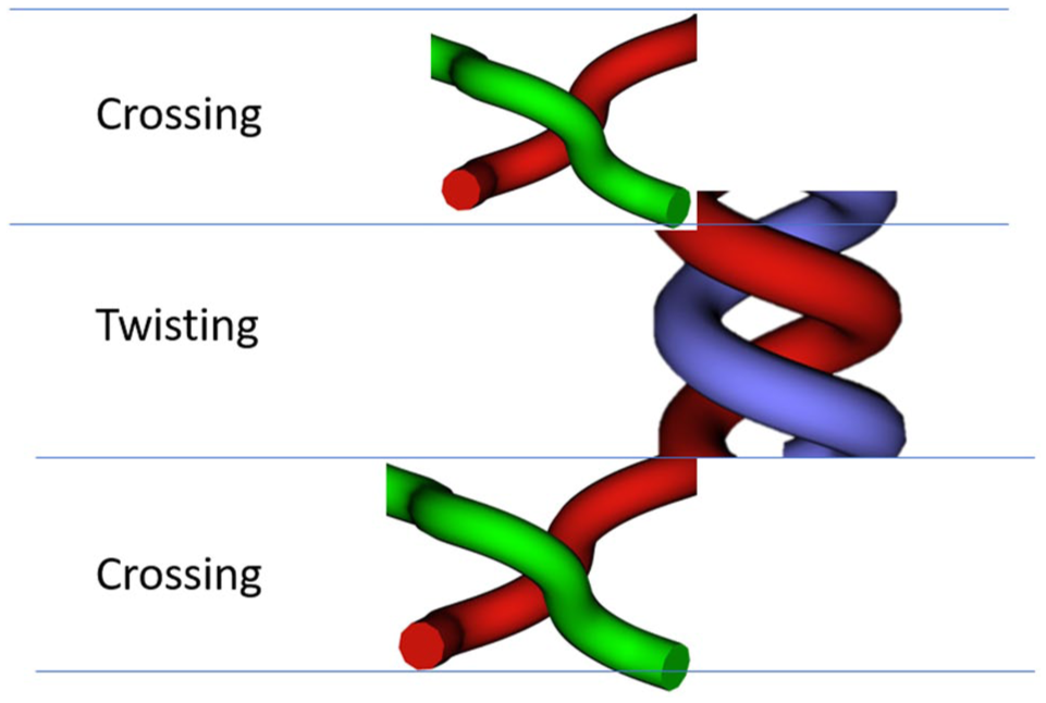
Combination of crossing and twisting produces a lace-type structure.
Such an interlacement is very natural for lace braiding machines, where one plate (gear) rotates, and its neighbor gears are waiting (Figure 5). However, the practical implementation of such a program on a machine with horn gears with continuous motion, without causing a collision between the carriers, is complex. The next section describes one application on such a machine where after bifurcation, the two yarns are twisted in the same way as a lace structure. Changing the direction of movement over one or two yarns, and a structure with asymmetric motion elements are demonstrated after that.
Implementation in a braiding machine with the continuous rotation of horn gears and steerable switches
In Figure 11 (Step 1) all switches are in the transfer position, so the carriers can move from one to another horn gear staying in their track. However, when all the switches are set to the keep position, a full horn gear rotation leads to a twist of the oppositely placed carrier. In addition to this twisting effect, the braid bifurcates from one 4-carrier round braid to two 2-carrier twisted threads. Programming such a bifurcation requires at least seven steps (see Figure 11).
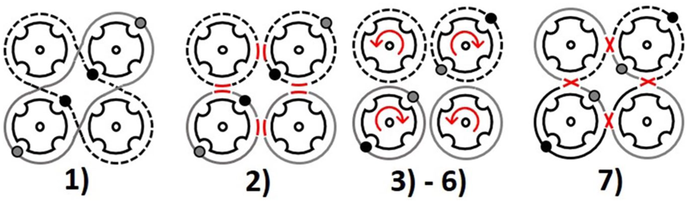
Bifurcation loop with twisted yarns: (1) initial position; (2) set all switches to “keep” position; (3) to (6) horn gear rotation (90° each step = 360°); and (7) set all switches to “transfer” position.
An example of a bifurcated braid with twisted threads is shown in Figure 12. In this case, the horn gear rotations with the switches in the keep position moved more than 360° to obtain a longer twist.
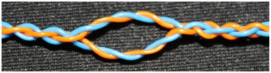
Round braid with a bifurcation of twisted threads.
Furthermore, the variation loop in Figure 11 led to the idea of changing the carrier direction through a change of its track. This is possible through a defined sequence of switch control and horn gear rotations. In Figure 11, Steps (3) to (6) show a 360° horn gear rotation. When rotating the horn gears only 180° and setting the switches back to the transfer position, each carrier would have changed its track and moving direction. This effect was used for the pattern in the section and for instance Figure 18, where an aimed switch toggling combined with an accurate horn gear rotation sequence envelopes a special braiding pattern which is related to the lace braiding technology.
Braiding program as a list of states
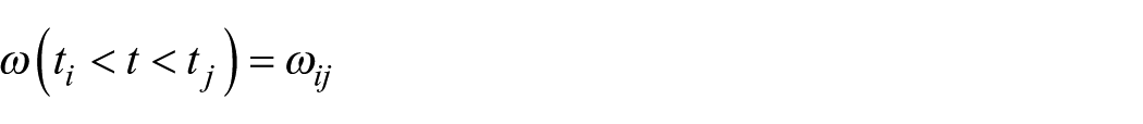
The design of complex structures requires user-friendly tools, where the relations and paths can be clearly visualized. In the current case this was carried out with specially developed CAD software. Previous versions of the algorithms are described by Kyosev.%24,%31 For the simulation process an object-oriented model comprising all the important parts of the machine was created, parts such as “Machine,” “Carrier,” “Horn gear with slots,” and “Switch.” Each carrier instance can be placed only on an empty slot of one horn gear and the slot coordinates determine the position of the carrier,
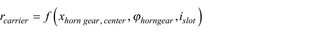
where
In order to use this approach for more flexible structures, the model was extended to incorporate a list of different machine states. One machine state,

For the convenience of the braiding process, the duration,

The simulation algorithm works as illustrated in Figure 13. After the machine with its horn gear configuration is loaded, the carriers are placed in their initial configuration. After that, the next state,
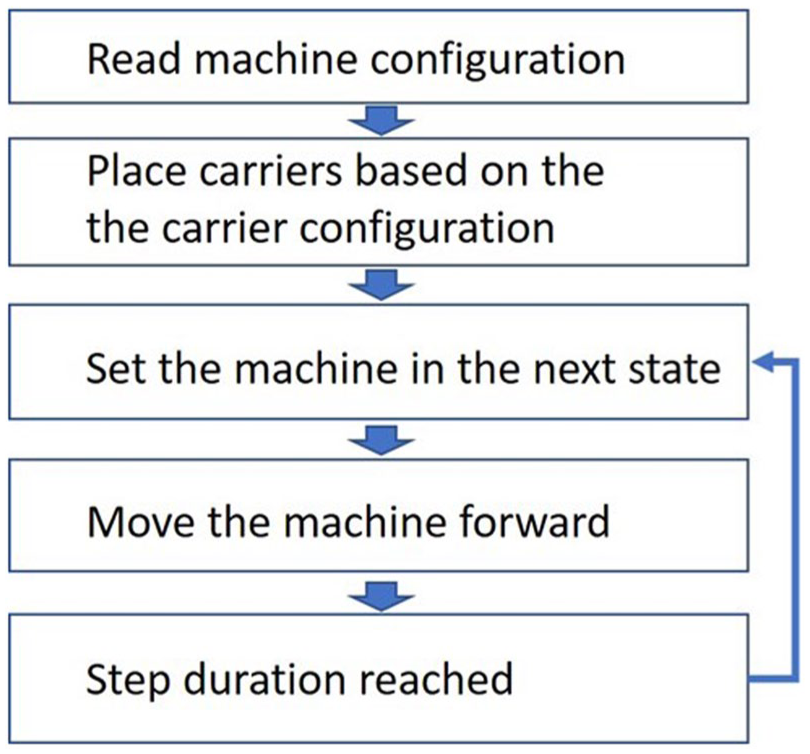
Algorithm of the simulation.
Development of lace structure with yarn changing its direction at each interlacement
For the development of a basic lace structure, where the yarn changes its direction after each interlacement, an initial configuration is shown in Figure 14, where all 16 horn gears are needed. Only the outer horn gears are directly involved, and the carriers are set as shown previously in a “one full, three empty” arrangement, and placed opposite on one horn gear.
Initial position for a lace braid on a continuous rotating horn gear machine through a track change.
The switches between the outer horn gears are set in the “transfer position,” while the inner switches are set in the “keep” position. When rotating the horn gears, all carriers are going to move in the outside tracks. A toggle of all outer switches to the keep position and a following horn gear rotation (Figure 14) would lead to a twisting effect, as shown in Figure 16. When the horn gear rotation is defined for only 180°, the opposite carriers will change their tracks and run in another direction. The outer switches are now set to the transfer position and the horn gears rotate 180° again. Now the steps are repeated in an endless loop, as illustrated in Figure 15.
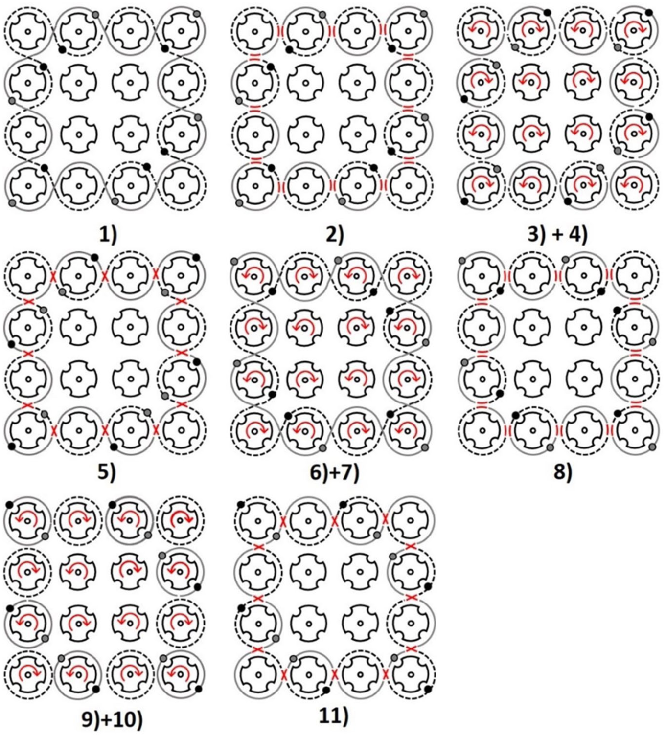
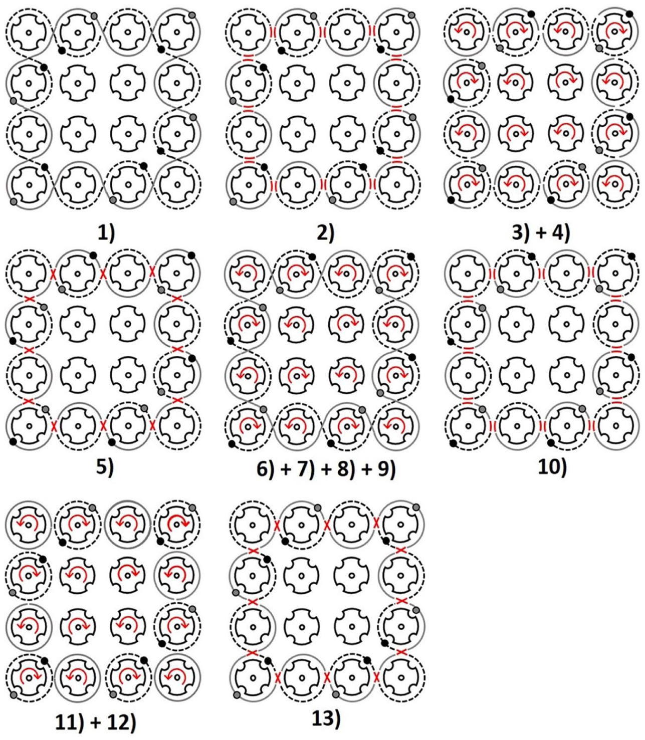
Variation loop for a track-change pattern: (1) initial position, (2) set all switches to keep position, (3) + (4) 180° horn gear rotation, (5) set the outer switches to transfer position, (6) + (7) 180° horn gear rotation, (8) set all switches to keep position, (9) + (10) 180° horn gear rotation, (11) set the outer switches to transfer position.
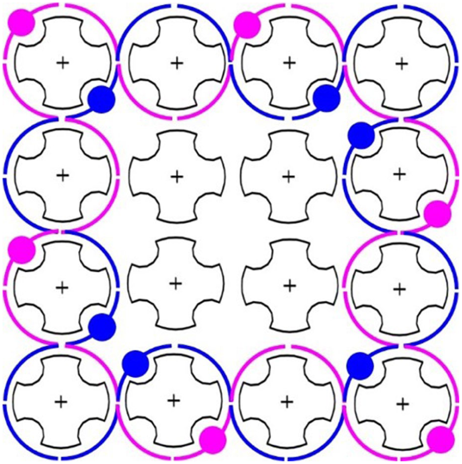
Before testing such a loop on the machine, a CAD simulation with the TexMind Braiding Machine Configurator was made. The braided simulation of this variation loop is shown in Figure 16.
Simulation of the variation loop shown in Figure 15 with the TexMind Braiding Machine Configurator.
When following the purple thread in Figure 16, the lace braided structure is obvious. The use of CAD software can help the operator validate the loop very quickly. The Graphical User Interface (GUI) of TexMind’s Braiding Machine Configurator is shown in Figure 17.
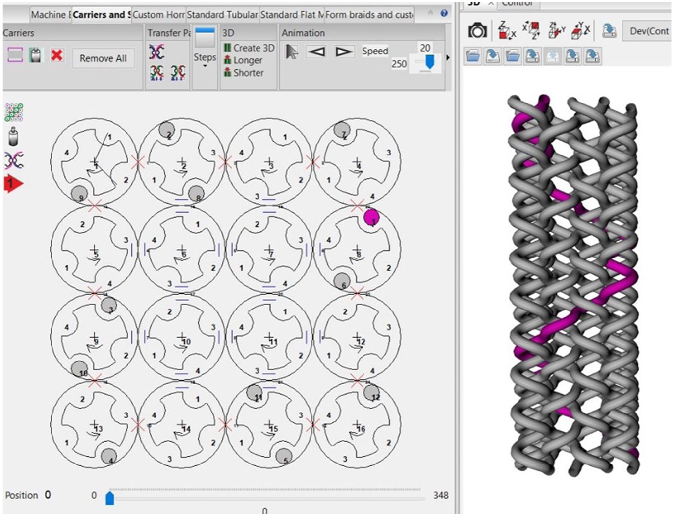
GUI of the TexMind Braiding Machine Configurator.
In classical maypole braiding, the carrier moves around the whole track plate on each horn gear, so all threads interact with each other. In the lace braiding pattern, the track and direction changes of a carrier cause every thread to interact with only two other threads. Concerning the variation loop, the motion area of every carrier is limited to only two horn gears. The steps developed by the simulation were entered into the VF braiding machine and a real braided example of this pattern was produced. This is shown in Figure 18: the limited thread movement is visible through the movement of each yarn in only two vertical columns.
(a) Real braided example of the variation loop from Figure 15; and (b) simulated 3D structure (due to the topology-based representation the yarn demonstrates the complete path of the carrier).
Development of lace structure with yarn changing its direction after the second or third interlacement
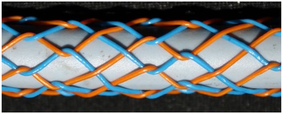
The previous example is a pure lace-type structure, where the yarn changes its direction at each interlacement with another yarn. However, if the yarn requires a longer piece in one direction (see Figure 19), its carrier has to move a greater length and pass around at least one more horn gear, extending its motion area.
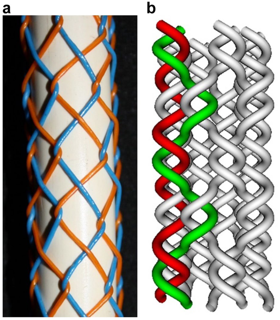
Extended carrier movement area by three columns in total realized by the movement of one carrier over three horn gears before a twisting motion: (a) real fabric and (b) simulation.
Figure 20 shows an example of a variation loop, where the carrier movement area is extended to three horn gears. The braided example of this loop in Figure 19 demonstrates how each thread now interacts with three other threads, moving over three vertical columns.
Extended carrier movement area: (1) initial position; (2) set all switches to keep position; (3) + (4) 180° horn gear rotation; (5) set the outer switches to transfer position; (6), (7), (8) + (9) 360° horn gear rotation; (10) set all switches to keeping position; (11) + (12) 180° horn gear rotation; (13) set the outer switches to transfer position.
The motion area and the resulting thread interaction can be extended to an even larger number of horn gears; it is only limited by the maximum number of horn gears. To achieve such a pattern, the opposite running carriers must be on one horn gear when the switches are toggled, otherwise the pattern will not work.
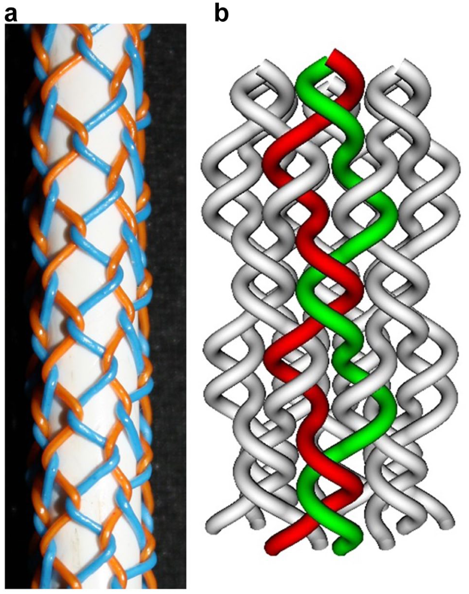
Figure 21 shows another example produced, where the carriers are running “as usual for tubular braids” for two interlacements and then twist, introducing a lace-type interlacement with the change of direction. Repeating this system in a loop, the single carrier runs through the whole track plate and makes contact with every horn gear, building a helix with stepwise pieces in the opposite direction.
Changing the carrier motion area during the braiding process from two- to four columns in a repeating loop.
Machine limitations and future possibilities
The method for patterning in the current research was implemented for a machine with mechanically connected horn gears, which all rotate synchronously. This configuration is cost-effective, but makes the patterning very complex, because the only way of changing the path of the carriers is by changing the switches. In recent years, braiding machine manufacturers have started to integrate individual drives on more horn gears, which has two effects: simplification of the patterning process and extension of the pattern possibilities. For the development of patterns with individually controlled drives, the algorithms and the graphical user interface had to be adjusted and extended. There are two different aspects in the software development for this case: the algorithmic and the user-interface aspect.
Concerning the algorithm, setting the angular velocity,
This value must not be not related to the horn gear radius or to the angular velocity of the neighbor gears or number of the slots. However, following any classical rules for the occupation of carriers and to avoid collisions is more difficult if the angular velocity is not related to the radius and number of slots. Actually, only a very limited set of angular velocities can be used for producing braided patterns without collision, because the carrier transfer from one gear to another can be done only if the sending slot exactly matches the position of the receiving slot, which has to be empty.
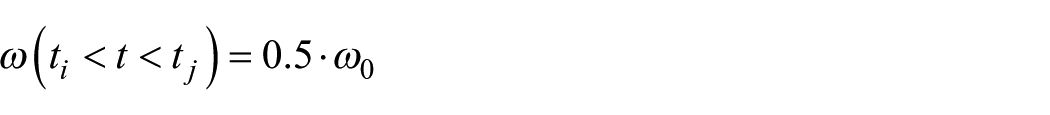
From this point of view, it would make sense that the users have only limited options for setting angaular velocities of the horn gears:
- Delay the horn gear rotation, so that the carrier reaches the transfer position one (or more) slot later. For this purpose, the carrier has to pass the arc length of one slot length for double the time, which means that the angular velocity has to have half of the original angular velocity,
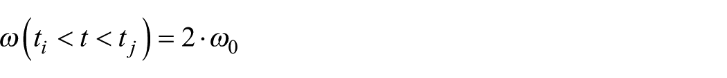
- Speed up the horn gear, so that the carrier reaches the transfer position one (or more) slot earlier, this requires doubling the angular velocity,
- In addition, for some situations, it would make sense to set the horn gear to stop, so that it does not rotate or change its rotational direction.
- If the user can make some changes to the speeds of the gears, after performing some pattern adjustments they would need to set the speed of the gear to its original angular speed,
These new options were requested by the software developer company of the Braiding Machine Configurator and are included in the latest version of the user interface (see Figure 22), but have not been tested for functionality. Nonetheless, the option to adjust the velocity will provide significantly more freedom in the patterning for braiding machines with individual gears and at the same time will increase the programming complexity. The investigation of these options, based on the simulation method, is currently in progress. The latest technical developments reported include a completely new, innovative magnetic switch system, which can change the speed and patterning of braids radically—proof that theoretical investigations of the methods and software development for such systems must continue.%32
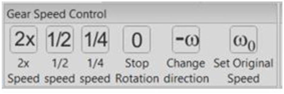
Buttons for the selection of suitable angular carrier speeds.
Discussion
Continuously rotating gears versus individually rotating (maypole dancing versus lace technique)
The developed method demonstrated that elements of the lace structures can be produced on a machine with continuously rotating gears with computer-controlled switches (classical maypole type). This capacity extends the patterning options of these machines, but could reduce their productivity because it introduces additional steps. Its application may not be productive enough and would make economical sense to be applied only for the specific applications where these pattern are required. For lace-type structures the lace machines provide potentially higher productivity, while for classical braid structures, where the yarn does not change direction (too often), the maypole braiding machine remains significantly more productive. The flexibility of the lace-type principle of independently rotating each gear remains valid. As demonstrated, the machine with continuous rotating horn gears has to perform more steps to obtain the same interlacement, which in the lace machine is achieved by fewer rotations. Put simply, this work was not undertaken as an attempt to promote computer-controlled machines, but only as a demonstration of how the methodology of lace-type patterns might be integrated in braiding machines with rotating gears, in case this has additional advantages for the design and manufacture of products.
Ideas for application areas
With the demonstrated approach, a completely new range of structures are possible using only one machine. In controlling the carrier motion area, one thread can only interact with one or more columns. For the medical sector, this could be used as an indicator if the braid is under the force of torsions. In addition to torsion, other alterations of the geometrical structure are more visible. Deformations in stents, for example, can harm their performance and must be avoided. The limitation in the carrier movement area is a significant advantage, for example in smart textiles or sensors. As shown in the braided examples, it is possible to braid a single thread in a defined number of columns. This effect could be used to place conductive threads into a defined area, making contact with only a selected number of other yarns, which could prove useful in sensor-based applications.
Conclusions
The pattern possibilities on a 3DBM (with computer-controlled switches and continuously rotating horn gears) are greater than on braiding machines with fixed switches. In addition to common braids like the flat, round, or square designs, the switch control allows the creation of more complex structures like bifurcations, bonding changes, or core/sheath structures.
This article provides an overview of the lace-type braiding technique and method to introduce such interlacements on a 3DBM with rotating gears (maypole braiding). The method was applied for the development of a few structures using pure numerical simulation, integrated into braiding machine emulation software. The obtained sequences of gear motion and stich states were programmed into the machine’s control software and real examples were produced as a verification of the method. The produced samples verifies, that with the numerical simulation was possible development new branch of unused pattern possibilities for these machines.
However, there is a disadvantage in using 3DBMs for lace braids because the whole production is run in an “adjust switch—then move” mode. For faster production, the machines will have to be constructed and controlled in a way that the changes in switch states will not necessitate the stopping of gears—something that is likely to be realized in the near future.
Footnotes
Declaration of conflicting interests
The authors declared no potential conflicts of interest with respect to the research, authorship, and/or publication of this article.
Funding
The authors received no financial support for the research, authorship, and/or publication of this article.