
Abstract
Background
The lack of a systematic selection framework for the selection of linear feed mechanisms in precision machine tools results in a mismatch between the performance of the mechanism and the specific application requirements in terms of accuracy, stiffness and load capacity, which restricts the optimization design of high-performance machining systems.
Objectives
We are committed to establishing a systematic classification system to categorize existing technologies and define their quantified performance boundaries, in order to guide the optimal choices of institutions and future innovation directions.
Methods
This review establishes a structured classification system, dividing mechanisms into four clear categories: typical linear drive mechanisms, linear linkage mechanisms, high-precision feed mechanisms and novel linear mechanisms. We compared and analyzed their working principles based on key parameters such as positioning accuracy, structural stiffness and load capacity; quantified their performance boundaries; and provided their applications. At the end of each section, a table is listed to summarize the content for easy reference.
Discussions
The analysis reveals that a typical linear feed mechanism, as the basic unit of machine tool linear motion, is widely used but has low accuracy. A linear linkage mechanism may not have high accuracy, but it can help machine tools complete specific structures. A high-precision linear feed mechanism has high precision, usually reaching the micrometer level, and is applied in scenarios with high precision requirements. The new linear feed mechanism represents the direction of technological development and guides the optimization design of machine tools.
Results
The performance-oriented classification framework developed in this study effectively resolves the selection challenge for precision linear feed mechanisms in machine tools. Its theoretical contribution lies in proposing a systematic performance spectrum, while its practical significance is to provide engineers with a clear decision-making tool for mechanism selection and to illuminate directed pathways for future innovation in precision motion systems.
Keywords
Introduction
As a core functional component of modern mechanical systems and automation equipment, the precision linear feed mechanism is essential. This device converts rotary motion into controlled, accurate straight-line movement and is tasked with achieving high-precision linear motion. It is widely employed across critical fields, including high-end manufacturing, precision machining, automated testing and intelligent manufacturing. In typical application scenarios, such as CNC (computer numerical control) machine tools, precision measuring instruments and automated production lines, its performance directly determines the equipment's machining accuracy, operational efficiency and service life. Conducting systematic research on precision linear feed mechanisms is crucial for enhancing the technological level of the manufacturing industry and advancing industrial technology. It is also important for strengthening independent R&D (research and development) and innovation in equipment manufacturing. In recent years, manufacturing has evolved towards greater precision, efficiency and reliability. As a result, linear feed technology—which refers to the mechanism's ability to precisely move components in a straight path—has achieved significant breakthroughs in motion accuracy, response speed and load-bearing capacity. These advancements strongly support the development of modern precision equipment.
This paper provides a systematic review of the research progress in precision linear feed systems for machine tools. Given the breadth and depth of the field, this review focuses on representative mechanisms from each category. The paper is structured as follows. Section 2 outlines the fundamental types of typical linear feed mechanisms, analyzing their working principles, structural characteristics and typical applications. Section 3 discusses the development history and practical applications of linear linkage mechanisms. Section 4 examines the technological evolution and application prospects of direct-drive feed mechanisms. Section 5 summarizes advanced linear feed mechanisms and their performance characteristics.
In the design and selection of practical machine tool precision linear feed systems, the aforementioned four categories of mechanisms exhibit distinct functional boundaries and performance stratification in terms of accuracy, stiffness and load capacity. Typical linear feed mechanisms—such as ball screws, gear racks and hydraulic transmissions—form the foundation of industrial applications. Their accuracy generally lies at the micrometer level, with medium high to very high stiffness and load capacity, making them suitable for most universal and heavy-duty CNC equipment. However, they face performance limitations in ultraprecision scenarios. Linear linkage mechanisms—such as Peaucellier–Lipkin linkages, Sarrus linkages and Watt linkages—can achieve theoretically exact or highly approximate linear motion at specific points along the trajectory. They offer high potential accuracy and are structurally frictionless but typically exhibit low to medium stiffness and load capacity. As such, they are often used in lightweight, precision-positioning applications or specialized mechanical systems, sometimes replacing conventional guides. High-precision linear feed mechanisms—including piezoelectric actuators, hydrostatic guides and planetary roller screws—extend performance boundaries to the nanometer level with very high stiffness. Some systems, such as hydrostatic guides, also support heavy loads, making them core components in ultraprecision machining, semiconductor manufacturing and heavy-duty high-precision equipment. In contrast, novel linear mechanisms—such as planar motors and micro-electro-mechanical systems (MEMS) micro-stages—represent the cutting edge of development, targeting extreme nanometer-level accuracy and multi-degree-of-freedom motion. These mechanisms, however, generally trade off stiffness and load capacity and are dedicated to specialized applications requiring ultrahigh precision under minimal loads, such as lithography machine stages and micromanipulation robots.
Thus, these four categories form a continuous technological spectrum ranging from “universal heavy-duty” to “ultraprecision micromotion.” Practical applications require clear distinctions and optimized selections based on specific accuracy grades, load requirements and stiffness needs. Following the review of each mechanism category, a dedicated summary section will clearly explain how to use the assessment criteria, helping readers determine which mechanism best fits varied engineering requirements. This approach aims to address the gap in existing research regarding mechanism selection guidance. The different categories of mechanisms complement one another in performance, offering a broad range of options for engineering selection and system design.
The basic classification of linear drive feed mechanisms
This section systematically classifies the common linear drive mechanisms in precision linear feed systems of machine tools, including ball screws, gear racks, synchronous belts, rope drives, cam mechanisms, hydraulic and pneumatic transmissions and rigid chain transmissions. We have conducted an in-depth analysis of the working principles of each mechanism and compared their performance characteristics and applicable scenarios, including accuracy, rigidity, load capacity, efficiency, etc., based on practical application cases, providing a theoretical basis and practical reference for mechanism selection and design under different working conditions.
Ball screw drive
The ball screw feed system has high rigidity and precision and has been widely used in precision machine tools and other fields. The basic function of ball screw feed transmission is to convert the rotary motion of the servo motor into the linear reciprocating motion of the platform. The ball screw structure diagram is shown in Figure 1. When the lead screw carries out rotary motion, the lead screw drives the ball inside the lead screw nut to carry out circular motion in the ball circulation device, and the circular motion of the ball in the ball circulation device drives the lead screw to translate. The balls in the ball screw pair are circulated in the raceway through the ball return device, return to their initial positions after one cycle and then move to the next cycle, thus forming a circular motion in the raceway.1–3
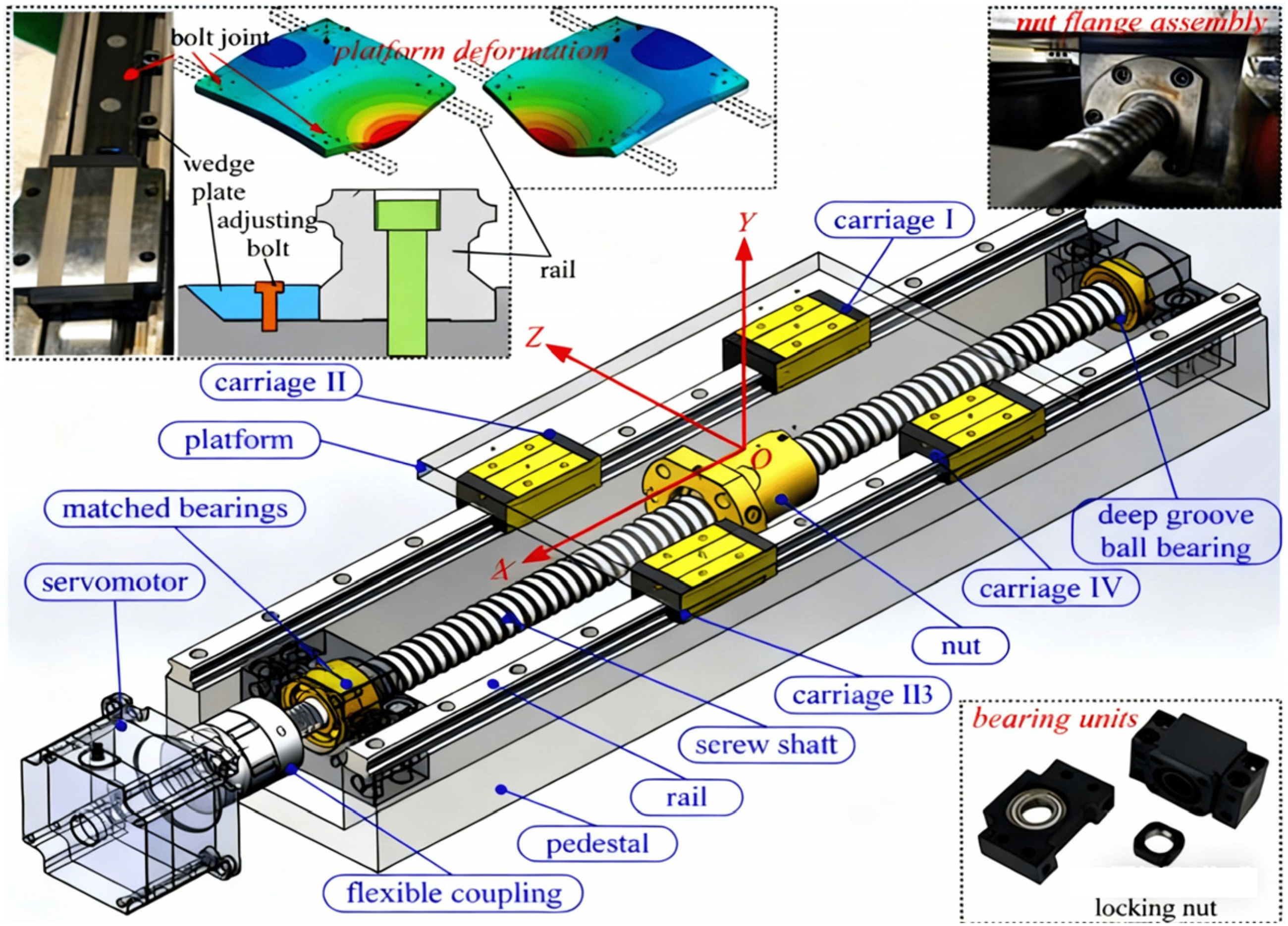
Schematic diagram of a ball screw feed system. 3
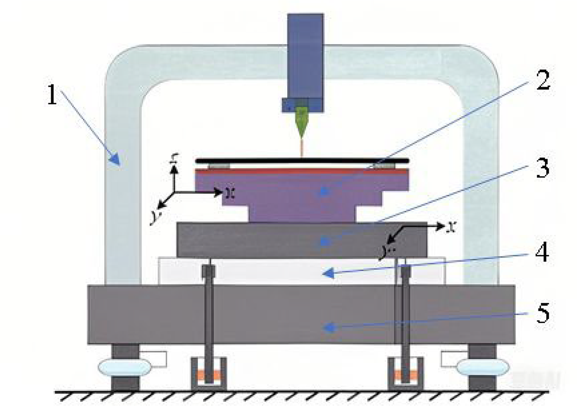
A dual-drive micro-feed mechanism based on nut-rotating ball screw pairs has been developed. 4 This design offers advantages such as a compact structure, rapid response, high resolution, long stroke range, strong load capacity, wide speed range, high transmission stiffness and ease of control. The drive mode can be selected from three servo control options: screw-only drive, nut-only drive and dual drive. Owing to the distinct characteristics of these drive methods in terms of electromechanical power coupling—with either the nut or the screw serving as the primary driving component—the dynamic performance of each drive method exhibits unique features, making them suitable for different processing requirements and technological applications. The dual-drive micro-feed mechanism is shown in Figure 2.

Mechanical structure of dual drive system. 4 (1) Machine bed, (2) linear guideway, (3) servo motor, (4) linear guideway slider, (5) coupling, (6) ball screw nut housing, (7) left bearing block, (8) ball screw, (9) ball screw nut, (10) right bearing block, (11) worktable connection block, (12) worktable and (13) worktable mounting surface.
During high-speed operation, the dynamic performance of ball screw drives is susceptible to disturbances caused by the ball recirculation mechanism, which can induce vibration and positioning errors. Additionally, frictional heating between the balls and the raceway results in significant temperature increases and subsequent thermal deformation of the screw. Typical operational limits include accelerations restricted to 1–2 G, temperature rises of 20–50 °C and associated thermal elongation ranging from 10 to 50 µm/m. These effects considerably compromise positioning stability, particularly under prolonged continuous operation. To mitigate these issues, countermeasures such as optimizing the ball recirculation structure, adjusting preload force, implementing oil cooling and applying thermal error compensation can be employed.
Rack-and-pinion drive
The rack-and-pinion transmission mechanism can realize the conversion of circular and linear motions; because of its smooth and simple operation, high transmission efficiency and large transmission power, it is often used as a lifting device for large-scale equipment and has a wide range of applications in offshore oil exploration platforms, large-scale wind turbines and water conservancy hubs. 5
A study of an electric preload rack with a pinion drive in an experimental rack is described. 6 The effects of preloading on the clearance, stiffness, friction loss and bandwidth of the rack–pinion drive system were studied experimentally. The article also explores the different electrical preload control structures and shows how the performance of the drive system can be optimized by adjusting the preload.
In a paper by Verl and Leipe, 7 a dual-motor position feedback control method for electrical preload and indirect control rack drive was proposed. Compared to state-of-the-art indirect control methods, the tracking error of the dual-motor position feedback controller is reduced by 59%. The dual-motor position feedback control method improves the accuracy of the machine without the need for a direct measurement system. The rack drive test bench is shown in Figure 3.

Dual-motor position feedback control loop. 7
The flexible rack device is constructed by connecting segmented tooth blocks with linking plates, forming a continuous yet unidirectionally bendable structure, as illustrated in Figure 4. When utilized as a lifting transmission mechanism, the device is motor driven and moves along a guided track. Its operational principle resembles that of gear meshing, but its flexible architecture allows it to bend and extend, accommodating complex motion paths. This design provides high load-bearing capacity, stable operation and low noise, while simultaneously improving the overall flexibility and operational reliability of the system. 8 However, meshing friction causes thermal deformation of the tooth surface. The meshing impact at high speeds can cause dynamic characteristic problems. 9 Based on the characteristics of a woodpecker's long tongue, which is composed of muscles and hyoid bones, can be wound around the head for storage and extends and bends in any direction, a robot with a flexible rack mechanism is designed. This mechanism uses two flexible rack gears, similar to the paired inner muscles of the woodpecker's tongue, which pass through each chain link. The rear of the manipulator is not restrained by a fixed rack and pinion. As shown in Figure 5, it is more flexible and easier to fold than other robotic arms.

Top view of the proposed robotic manipulator. 9

(a) Main body, (b) backbone and (c) drives. DC: direct current. 9
The operational principle of this mechanism relies on a rigid chain backbone interconnected with screws. Two flexible rack-and-pinion systems, constrained within grooves on both sides at a limited parallel spacing, run along the structure. By fixing the end connecting rod and selectively actuating one of the racks, the flexible deformation of the rack is restricted by the spacing constraint. This restriction forces the rigid chain backbone to bend synchronously into a uniform circular arc. A dual-drive unit—fixed to the base and movable along the chain—utilizes its internal rack-and-pinion transmission to provide coordinated driving force and precisely lock the position of each chain link along the curved path. As a result, a safe and controllable horizontal bending motion of the robot is achieved.
This mechanism employs a hybrid rigid-flexible design, integrating a rigid joint chain with a flexible rack-and-pinion system. This configuration provides high load-bearing capacity in the vertical direction while enabling flexible bending motion in the horizontal plane, ensuring both operational safety and torsional resistance. The two racks are independently driven, allowing for precise control over elongation, bending and the end effector's angle by regulating their speed differential. This capability facilitates accurate tracking of complex trajectories. Consequently, the device is suitable for a wide range of applications, including pipeline inspection, internal maintenance of industrial equipment and medical endoscopes and assistive robots.
While the gear-rack mechanism is well suited for high-power and long-stroke transmission applications, it requires backlash control on the order of tens of arcseconds to maintain precision. The transmission relies on tooth surface meshing for motion conversion; however, under high-speed operation, impact vibration induced by meshing clearance can lead to dynamic instability. Furthermore, friction at the meshing interface generates heat, resulting in thermal effects and subsequent deformation of the tooth profiles. To mitigate these issues, performance can be improved by adopting a dual-motor electric pretensioning control strategy with position feedback to reduce backlash, combined with lubrication cooling and thermal error monitoring with compensation. Specifically, a dedicated backlash-reducing mechanism and high-quality lubrication can be employed to minimize friction losses. When integrated with full closed-loop real-time correction and model-based friction compensation algorithms, these measures enable high-precision and smooth motion over long strokes.
Belt drive
The belt drive 10 mechanism achieves a positioning accuracy of ±2 mm, making it suitable for automation applications involving long spans (typically >3 m) and low to medium loads. To ensure thermal stability, a composite material with a low coefficient of thermal expansion is employed together with a temperature-compensated tensioning mechanism, effectively minimizing positioning errors induced by thermal drift. Dynamic stability is attained through the inherent damping properties of the toothed meshing interface, combined with an adaptive vibration suppression algorithm embedded in the servo system. This synergy allows the mechanism to maintain a smooth operation during start–stop and variable-speed processes. Collectively, these features constitute a long-stroke linear transmission solution that balances precision, thermal robustness and dynamic controllability. The system is shown in Figure 6.

Linear drive mechanism of a large-span synchronous belt. 10 (1) Driven wheel, (2) synchronous belt, (3) load slider, (4) base, (5) guide rail, (6) servo motor, (7) driving wheel, (8) slide and (9) bearing housing.
Rope drive
As a transmission form that transmits precision motion through flexible media, precision flexible transmission has important applications in the field that requires high transmission accuracy. A steel wire rope has excellent tensile strength and good flexibility and is used as a flexible medium in precision flexible transmission devices. 11 Compared with the traditional rigid transmission mechanism, the flexible transmission mechanism has the advantages of simple structure, low loss and strong mechanical compatibility. 12
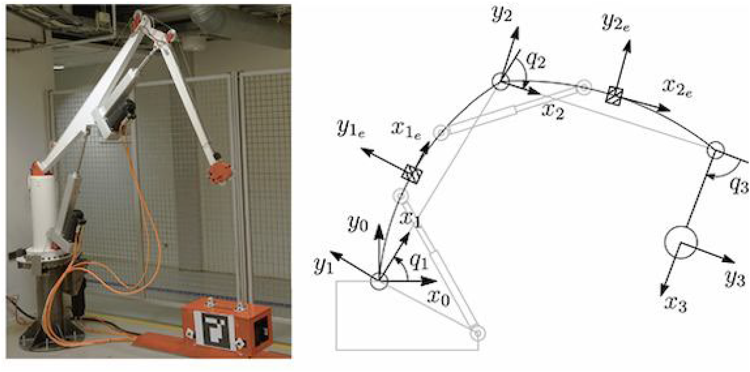
Gen Endo et al. 13 designed a 10-m-long coupled-rope-driven articulated robotic arm “Super Dragon” for the decommissioning mission of the Fukushima Daiichi nuclear power plant in Japan. The principle is shown in Figure 7. It adopts a coupled-rope-driven mechanism and a gravity compensation mechanism based on synthetic fiber ropes to overcome the problems of large volume, heavy weight and difficult deployment of traditional rigid transmission structures, achieving a light weight, compactness and high radiation resistance. It can carry measurement equipment to carry out fuel debris exploration operations in the pressure vessel of the nuclear power plant. The feasibility of the robotic arm was verified through basic motion experiments of 5.7-m and 10-m prototypes (such as endpoint target capture and horizontal posture maintenance).

Schematic diagram of a rope transmission joint-control system. DC: direct current. 13
The core of the dynamic stability of rope transmission lies in suppressing the vibration caused by its flexibility. To avoid instability, the transmission speed usually needs to be below the critical value of 30 m/s to prevent destructive lateral vibration. The working tension should be maintained at 10%−15% of the rope breaking force to ensure rigidity while reducing slippage. It is best to control the distance between the pulleys within 0.5–1.2 m and use high damping materials to effectively suppress resonance and ensure smooth transmission.
Cam mechanism
Cam mechanisms are used to convert rotary motion into linear motion or complex curved motion. It realizes a specific motion trajectory and function through the shape design of the cam and the fit of the followers. In modern mechanical design, the cam mechanism is widely used in various mechanical structures because of its advantages of simple structure, diverse functions and convenient adjustment. 14
The cam mechanism drives the driven component to complete a precise reciprocating or swinging motion by rotating a cam with a specific profile; the motion pattern is completely determined by the cam profile. The main advantage of this institution is its ability to achieve complex motion trajectories with micrometer-level repetitive positioning accuracy, with a maximum speed of thousands of revolutions per minute and a compact structure that is reliable in operation. The main disadvantages are that the machining accuracy of the cam profile is extremely high (usually at the micrometer level), the high pair contact is prone to wear, the service life is often in the millions to tens of millions of cycles and the motion law is fixed and cannot be adjusted. By adopting improved motion laws such as sine acceleration, the maximum acceleration can be reduced by 30%−50%, and combined with the lightweight design and preload optimization of the driven system, vibration and noise can be effectively suppressed, ensuring a smooth operation at 1500–3000 rpm. The core of the design of the cam mechanism lies in the design of the cam profile, which determines the motion law of the follower. 15
Li Gao et al. 16 addressed the coupling gap problem in the upper-limb cam mechanism by using the adaptive non-dominated sorting genetic algorithm (NSGA-II) for global optimization and developing a data-mapping cam mechanism with dynamic feedback from the motion trajectory model and the solid model. Experiments show that the cam motion deviation can be adjusted through dynamic data feedback. The structure of the exoskeleton cam variable torque structure is shown in Figure 8.

Variable torque structure of bone cam. 16 (1) Rib, (2) cam, (3) rocker, (4) roller, (5) base and (6) nitrogen gas spring.
Hydraulic transmission mechanism
As one of the three major transmission forms, hydraulic transmission has the advantages of a large output power, a relatively small weight per unit power, relative ease in achieving stepless speed regulation and overload protection compared with mechanical transmission and electrical transmission, a simple operation and easier-to-achieve automation. 17 It is precisely because of the above advantages that hydraulic transmission has a unique role and occupies an important position in the field of power transmission and control. 18 In the fields of construction machinery (e.g. excavators and bulldozers), industrial equipment (e.g. presses and injection molding machines), aerospace (e.g. aircraft landing gear and servos), automotive industry (e.g. brake systems and suspension systems), etc., applications are also common. 19
In an article by Andrej Cibicik et al., 20 a hydraulic transmission manipulator is mentioned, and the mechanical body is composed of a flexible boom and a hydraulic drive system, which includes a main boom, an articulated arm, a double hydraulic cylinder, etc., and the mechanism drives the boom pitching movement through the piston rod telescopic, including a piston/cylinder mass, a hydraulic valve and an oil circuit. The hydraulic oil controls the flow through the proportional valve, drives the piston rod to expand and contract and changes the length of the hydraulic cylinder to promote the rotation of the boom so that the change in the length of the hydraulic cylinder is converted into the rotational motion of the boom around the hinge.
The mechanism can adapt to complex working conditions and operate at low flow, and the hydraulic system can still generate an effective excitation force at a flow rate of 30 L/s, whereas the traditional system requires a flow rate greater than 45 L/s. The mechanism's all-metal turbine valve block can operate stably in a 150 °C downhole environment and exhibits high temperature resistance. It is suitable for the development of offshore light cranes, long-boom precision work and hydraulic systems. The schematic diagram of the structure is shown in Figure 9.
Hydraulic transmission manipulator physical and structural drawing. 20
Pneumatic transmission mechanism
Pneumatic technology, which can also be called pneumatic transmission technology, is a technology that realizes various industrial automation production. 21 After long-term development and innovation, pneumatic technology has occupied an important position in the machinery industry and has been applied in various industries.22–24 Compared with other technologies, pneumatic technology has the characteristics of zero pollution and low cost. China regards green development and other ideas as the basic policy of Made in China and also creates a new space for the application of pneumatic technology. 25 At present, pneumatic technology is mainly used in industrial production, 26 medical rehabilitation field 27 and so on.
Zhi-cheng Qiu et al. 28 proposed a new type of manipulator for development. The robotic arm uses a rodless cylinder as the main driving source to achieve large-scale translation of the slider, and at the same time, a piezoelectric ceramic plate (PZT) symmetrically arranged on a flexible beam serves as an anti-vibration actuator, forming a pneumatic–electric hybrid driving system. Its working principle is based on a parallel-control strategy: the rodless cylinder performs coarse positioning under proportional-derivative control, while the PZT generates real-time vibration suppression force based on the vibration signal detected by the sensor in the middle of the beam, combined with adaptive fuzzy control, and eliminates system phase lag through filtering and delay compensation technology, thereby achieving high-precision positioning and active vibration suppression simultaneously. This system is suitable for precision assembly and handling tasks with low to medium loads and workspaces ranging from hundreds of millimeters, with positioning accuracy up to the micrometer level. In terms of thermal stability, due to pneumatic systems’ sensitivity to temperature fluctuations, their positioning repeatability may be affected by changes in gas-source pressure. However, PZT materials exhibit good thermoelectric stability at room temperature, and the control algorithm has some adaptive compensation capability for slowly varying parameters. In terms of dynamic stability, the hybrid control structure enables the robotic arm to cope with wideband disturbances, and the adaptive fuzzy strategy can adjust control parameters online, thereby maintaining high vibration suppression robustness and trajectory tracking stability even under changing loads or motion trajectories. The system architecture diagram is shown in Figure 10, and the experimental system is shown in Figure 11.

Three-dimensional model of translational flexible manipulator. 28
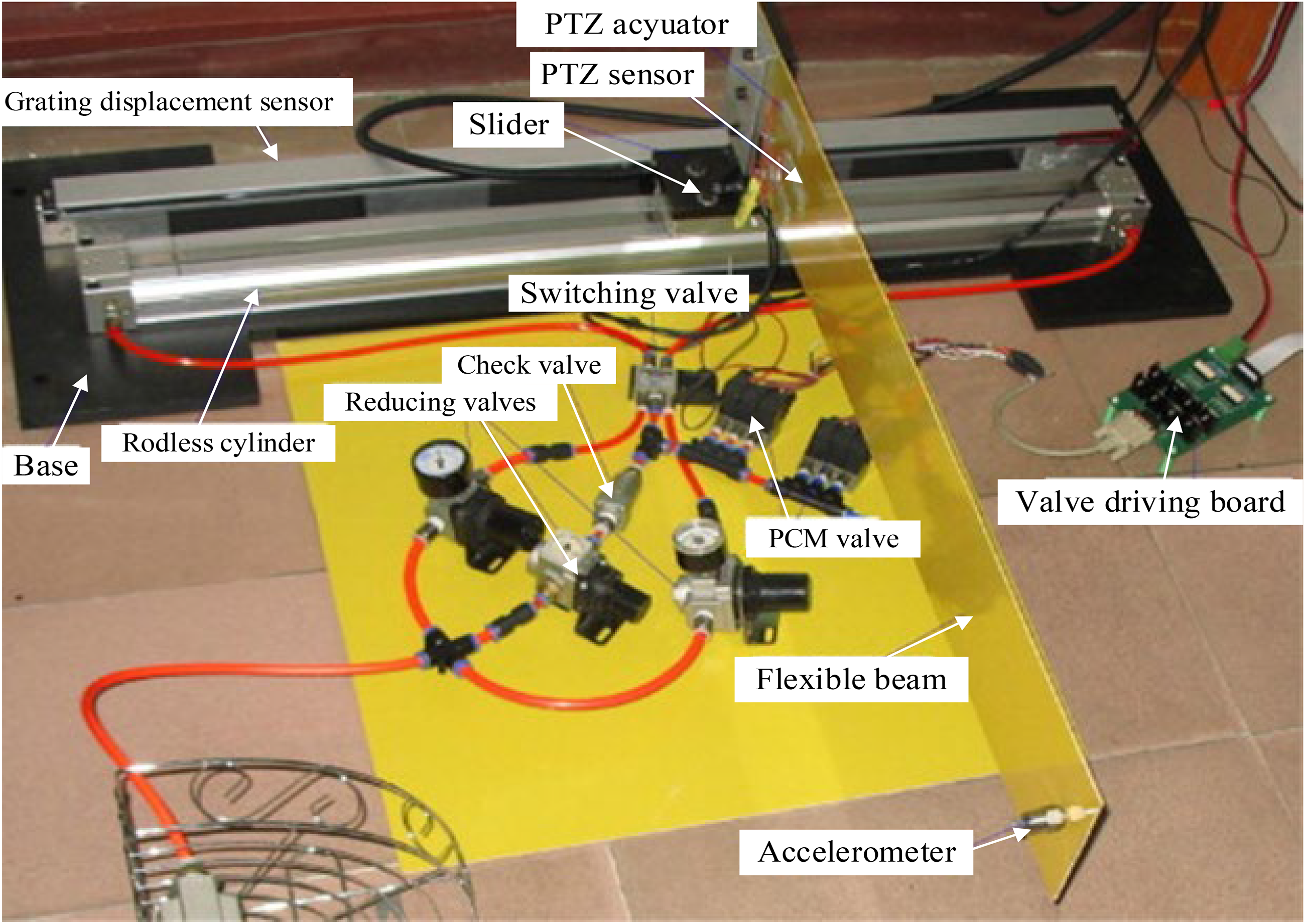
Experimental setup. 28 PTZ sensor is a device used to simultaneously measure the “position” and “deformation/torque” of a robotic arm. PCM sensors specifically refer to piezoelectric ceramic chips used as “modal sensors”.
Rigid chain drive mechanism
Chain drive is a reliable mechanical transmission method, whose core advantage is precise synchronous transmission under long-distance and heavy-load conditions, with a constant transmission ratio, a compact structure and good environmental adaptability. It is particularly suitable for harsh industrial environments, such as coal mine scraper conveyors, as described in the article, which are subject to dust, heavy loads and strong impacts. However, its transmission accuracy is significantly affected by the “polygon effect” and dynamic fluctuations and is not the choice for high-precision transmission. The longitudinal torsional coupling vibration revealed by research indicates that when the load suddenly changes, the chain will experience severe speed and tension fluctuations, and the uneven force on the double chain will cause torsional vibration, directly affecting the dynamic stability and smooth operation of the system. Its disadvantages mainly include noise, wear, fatigue fractures caused by vibration and impact and increased system complexity of the tensioning device required to maintain tension. To solve the above problems, small-pitch chains can be used to reduce the influence of polygonal effects, high-precision sprockets with tooth profile optimization can be used, tension devices can be added to maintain constant tension, inertia wheels can be installed on the driven shaft to smooth speed fluctuations and longitudinal torsional coupling vibration can be suppressed through structural optimization. Therefore, chain drives are mainly used in the heavy industry sector, where high transmission accuracy is not required but reliability, load-bearing capacity and the ability to withstand harsh working conditions are emphasized. The classic chain drive mechanism is shown in Figure 12.

Classical chain drive mechanism. 28
Section 2 summary
This section systematically describes typical linear drive feed mechanisms and, based on their transmission principles, constructs a clear hierarchical spectrum of performance in terms of accuracy, stiffness and load capacity. The spectrum covers all kinds of mechanisms, from high-precision ball screw and heavy-duty rack-and-pinion drives to light belt drives and economical pneumatic and chain drives, serving specific application scenarios.
However, in-depth analysis shows that the performance boundary is fundamentally subject to their respective physical working principles: the friction and thermal deformation of the ball screw, the meshing clearance and dynamic impact of the gear and rack, the material relaxation of the belt drive and the polygonal effect of the chain drive are the inherent bottlenecks that traditional mechanical contact drive cannot overcome. Although strategies such as pretension control, dual-drive configuration, advanced thermal management and an adaptive control algorithm can be optimized and compensated at the system level, these efforts primarily aim to alleviate rather than eliminate the above limitations.
With future demands for ultrahigh accuracy and high dynamic response, typical linear drive mechanisms have gradually reached their upper performance limits. This recognition provides an inevitable logical starting point and an innovative impetus for the subsequent sections to explore high-precision mechanisms based on new principles, such as noncontact and direct drive. Future research should go beyond traditional optimization paradigms, revolutionize from the system architecture level and focus on intelligent methods and advanced process paths. To be specific, the dynamic compensation control algorithm based on artificial intelligence (AI) can be introduced to construct the digital twin model of system response by using the real-time collected displacement, temperature, vibration and other multi-source sensing data, so as to realize disturbance prediction and feedforward suppression. At the same time, combined with the intelligent optimization technology of process parameters, the driving parameters are adaptively adjusted in the processing process to match the accuracy and dynamic performance requirements under different working conditions.
The principle, advantages and disadvantages, and scope of application of a typical linear feed mechanism are summarized in Table 1.
Comparison of typical linear feed mechanisms.
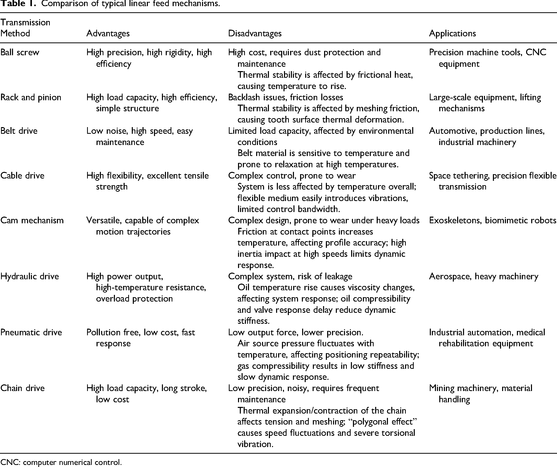
CNC: computer numerical control.
Basic classification of linear linkage mechanisms
This section focuses on linkage mechanisms that can achieve approximate or precise linear motion without the need for guide rails and divides them into two categories: precise linear motion mechanisms and approximate linear motion mechanisms. We provided a detailed introduction to precise linear mechanisms, such as the crank slider mechanism, Scottish yoke mechanism, Peaucellier–Lipkin mechanism, Sarrus mechanism and approximate linear mechanisms, such as Watt four-bar linkage, Roberts, Chebyshev and Hawkins. By analyzing their structural principles, motion trajectories, and performance advantages and disadvantages, this paper explores the innovative applications of these mechanisms in fields such as robotics, precision measurement and biomimetic equipment.
Accurate linear motion mechanism
A linear trajectory linkage mechanism is a linkage mechanism with an approximately or exactly straight-line segment of the movement trajectory at a point on the connecting rod. It has a wide range of applications across various machinery industries because it enables frictionless linear motion without a guide rail.
Crank slider mechanism
The crank slider is used in conjunction with other linkage systems, such as the Sarrus linkage or the four- or five-bar linkage, to convert circular motion into linear motion. Many common machines use a crank-and-slide mechanism, such as four-stroke internal combustion engines, bull planers and mechanical presses. 29
Talli and Giriyapur 30 designed a variable stiffness joint based on a symmetrical crank slider mechanism. This joint is mainly composed of an input disk, an output disk, a spring rod and a symmetrically arranged crank slider mechanism and integrates two sets of drive units for position control and stiffness adjustment. The joint motor drives the input disk to rotate through a harmonic reducer, which in turn drives the spring rod to push the output disk to move, achieving position control. The stiffness adjustment motor drives the symmetrical crank slider mechanism through gear transmission, converting rotational motion into linear motion, causing the sliding fixture to move symmetrically along the convex groove of the input disk, thereby changing the effective length of the spring rod. By adjusting the length of the deformation section of the spring rod, the joint stiffness can be continuously adjusted. The spring rod undergoes elastic deformation when subjected to external torque, causing passive deflection and further altering the system's stiffness, enabling independent control of position and stiffness. The crank slider mechanism can achieve continuous stiffness adjustment. Compared with ball screws, it responds quickly, improves energy efficiency through the mutual conversion of elastic potential energy and kinetic energy, adopts balanced load distribution to reduce local stress concentration and has a compact structure. The input disk is driven with a joint motor and harmonic reducer to precisely control the angle of the output disc. The stiffness ring adjusts the spring's effective length to set the target stiffness via the stiffness motor and crank slider mechanism. On this basis, an impedance control strategy can be adopted to adjust stiffness, damping and other parameters in real time so that the joint presents different “tactile sensations” from soft to hard under external force, achieving a safe and smooth interaction. It has strong development prospects in medical robots, bionic robots, flexible grasping, service robots and industrial automation. The structural diagram is shown in Figure 13.

Three-dimensional structure of a symmetrical crank slider mechanism. 30
Stop yoke mechanism
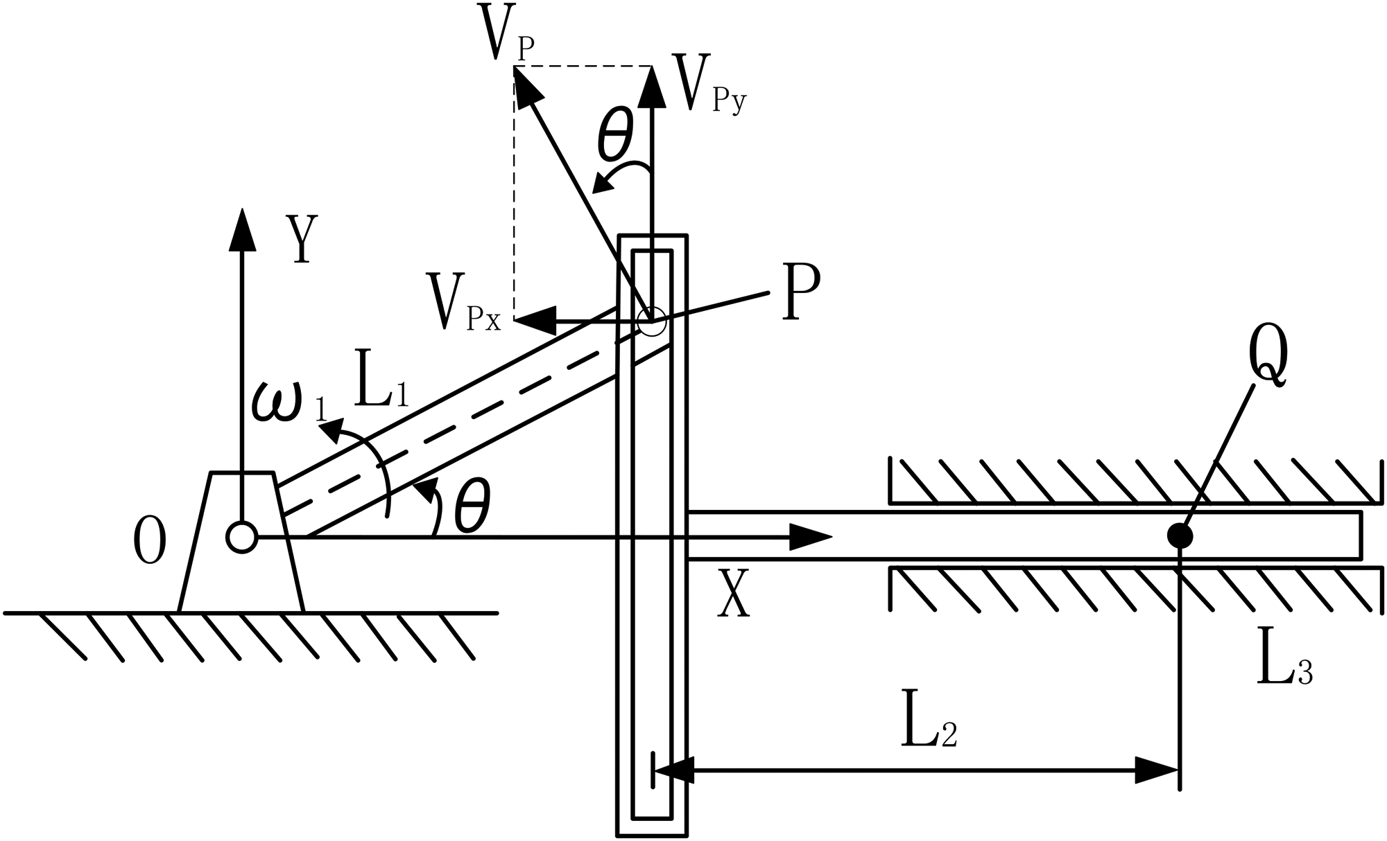
The Scotch yoke is composed of a slide and a slide. As the transformation mechanism of the crank slider mechanism, the ratio of the crank radius of this mechanism to the length of the connecting rod is zero, so the mechanism has no higher-order inertial force. 31 The yoke mechanism converts rotary motion into linear reciprocating motion. Its working principle is to drive the crank to rotate and drive the slide bar on the crank to perform linear reciprocating motion along the X-axis in the groove. If the input rotational motion is stable, the output reciprocating motion will proceed in a sinusoidal pattern. This process is reversible; i.e. if a reciprocating motion is applied to the slide bar, the stop yoke can also convert linear motion into rotational motion. The structure is shown in Figure 14.
Peaucellier–Lipkin mechanism. 31
Junzhi Yu and others, 32 taking advantage of the yoke mechanism's linear reciprocating motion being sinusoidal, designed a robot capable of dolphin-like propulsion, as shown in Figures 15 and 16. The mechanism is driven by two motors; the main motor drives the Scottish yoke to produce sinusoidal oscillation, and the crank length is adjusted by the screw-and-rack mechanism from the motor, so as to achieve independent adjustment of the oscillation amplitude. The output motion is converted into an up-and-down oscillation via a rack-and-pinion transmission, simulating the dorsal and ventral motions of a dolphin, and the feasibility is verified. This mechanism can produce the required kinematic properties, offering a new design idea for dolphin-like robots.

Main view of the propulsion mechanism. 32

Adjustable yoke mechanism. 32
Peaucellier–Lipkin institution
The Peaucellier–Lipkin mechanism can achieve precise linear motion and performs better at large displacements than near-linear mechanisms such as the Roberts mechanism and the Chebyshev linkage. The Peaucellier–Lipkin mechanism has eight connecting rods and 10 joints with a single degree of freedom (DOF), so only one prime mover is needed for precise positioning. 33 The Peaucellier–Lipkin mechanism is shown in Figure 17.

Peaucellier–Lipkin agency. 33 (1) Fixed seat, (2–8) connecting rod and (A–F) connection point.
Sanditi Khandelwal et al., 34 based on the Peaucellier–Lipkin linkage, proposed a haptic device that provides accurate linear force feedback. Its applications include surgical robots and remotely controlled robotic arms, enabling the operator to obtain real haptic feedback and improve the accuracy and control of the operation.
The single-DOF linear tactile device is shown in Figure 18. When the motor drives the crankshaft to rotate, the crankshaft pushes the connecting rod, causing the entire mechanism to move in coordination. Due to the geometric characteristics of the Peaucellier–Lipkin mechanism, this rotational motion is converted into linear motion through linkages. The force sensor transmits the measured force feedback signal to the control system, realizing precise force output and position control through a closed-loop control strategy.

Single-degree-of-freedom linear tactile device. 34
Sarrus agency
The Sarrus linkage shown in Figure 19 is a spatial six-link structure with two sets of three parallel adjacent joint axes, which does not depend on rails or other mechanical linkages to convert a limited circular motion into linear motion and vice versa. 35 This mechanism includes only rotating pairs, without motion and spiral pairs, with a simple structure, high transmission efficiency and stable motion. The disadvantage is that the input–output relationship is nonlinear, and the reverse stroke does not have self-locking, which takes up a lot of space.

Sarrus mechanism. 35
Vu Linh Nguyen 36 proposed a new type of adjustable constant-force mechanism (CFM), whose overall structure is shown in Figure 20. Under the motion constraints of the three legs of the Sarrus linkage, the motion platform (connecting rod 4) can be translated along the z-axis without guides. The combination of gears and springs converts linear elastic force into a constant force, reducing energy and torque requirements and enabling the mechanism to provide a constant output force over a wide range of displacements. Compared to traditional rigid CFMs, this design does not require preloaded springs, reducing the energy required to adjust constant-force levels. The experimental results show that when the spring is attached to the mechanism, the drive's peak torque is significantly reduced by 93.6%. However, due to the large number of gears and joints used in the mechanism, it can cause significant friction problems.

Constant-force mechanism (#CFM) structure based on gear Sarrus connecting rod and linear spring. 36
In the field of renal intervention robots, Hu et al. 37 used a precision linear drive device based on the Sarrus linkage mechanism (as shown in Figure 21), which serves to accurately push the flexible ureteroscope forward and backward within the body, improve the controllability of surgical operations, reduce the risk of tissue damage and ultimately assist doctors in safely and effectively performing intracavitary urological surgeries such as kidney stone lithotripsy, narrow-segment dilation or precise lesion examination.

Linear mechanism model of an intrarenal interventional robot. 37
Linkage mechanism based on five arches
Yu and others 38 invented a linkage mechanism based on five arches that controls the relative rotation angle between modules and actively offsets the system center of mass to drive pure rolling motion. It adopts a composite trajectory planning method based on Bézier curves and cubic polynomials to achieve smoothness and high-order differentiability of joint motion, thereby improving motion accuracy and reducing impact. Institutions have the advantages of continuous motion and controllable energy consumption, especially by significantly reducing energy consumption through optimizing the height of the center-of-mass trajectory. However, its workspace is constrained by symmetry and sensitive to joint friction. In terms of dynamic stability, the model combining Lagrange equations and Rayleigh dissipation function effectively describes the system dynamics, and simulation verification shows that it can maintain stable rolling under two typical acceleration plans, demonstrating good dynamic performance and control potential. The schematic diagram is shown in Figure 22.
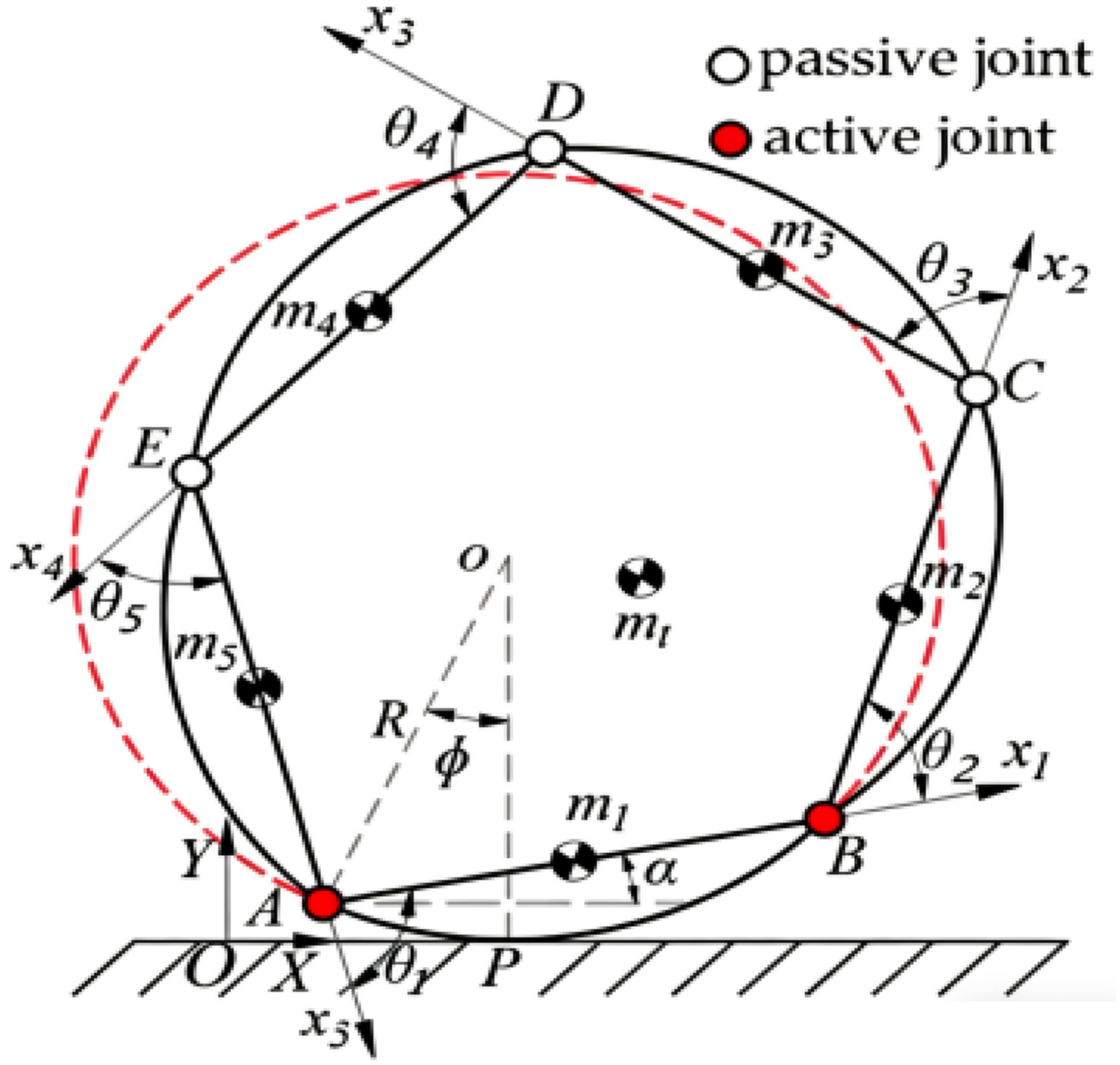
Schematic diagram of a linkage mechanism based on five arches. 38
Bricard linear mechanism
The Bricard mechanism is a set of single-DOF closed-loop overconfined space six-link mechanisms, which have been proposed by Bricard since the beginning of the 20th century and divided into six types, 39 which has always aroused the interest of many scholars. 40 Due to its high mobility, high storage, good composability and superior foldability, the Bricard linkage mechanism has been widely used in various fields, including parallel and symmetrical robotic arms, 41 deployable space structure (such as solar panels and antennas), ship equipment and flexible mechanisms. One of the forms of the Bricard mechanism is shown in Figure 23.
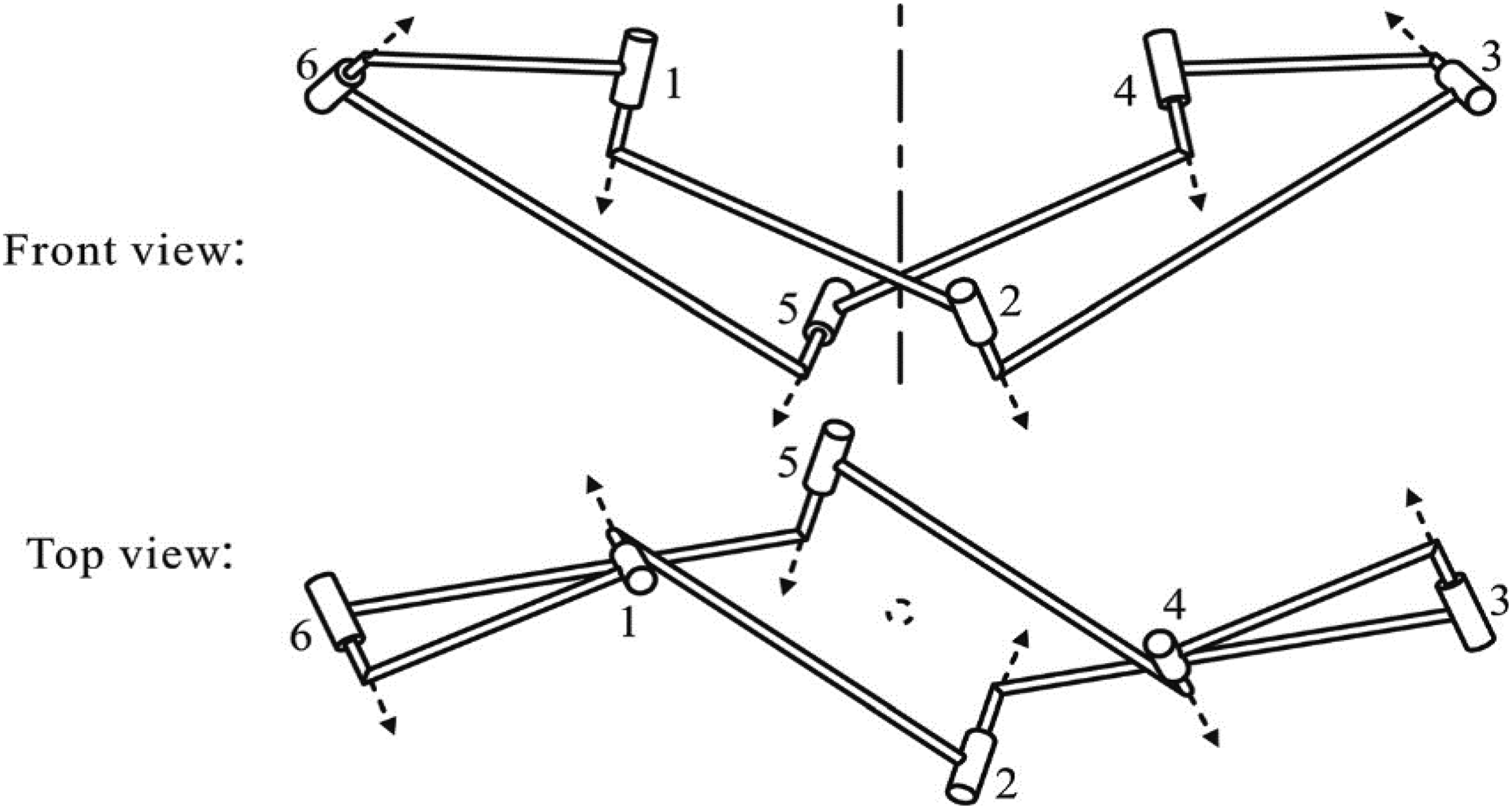
Two closed states of the general line-symmetric Bricard mechanism. 39
Jian, 42 in view of the excessive lateral force problem in stamping equipment during stamping production, based on the symmetrical Bricard mechanism shown in Figure 24, proposed a punch application mode, as shown in Figure 25. In the design of the stamping mechanism, three independent motors serve as the power source, optimizing force distribution, ensuring balance and synchronization during movement and reducing the risk of failure caused by uneven forces or unsynchronized joint movement. Since the Bricard mechanism itself has a single DOF, with the cooperation of the three drive motors, not only is the movement synchronized, but the load is also shared, so that a smaller power motor can take on a larger workload. In addition, the high rigidity of the overrestrained mechanism enhances its ability to withstand large loads.

Schematic diagram of the Bricard mechanism model. 42

UR parallel mechanism with the Bricard platform. 42
The principle, advantages and disadvantages, and scope of precision linear motion mechanism application are shown in Table 2.
Comparison of precision linear motion mechanisms.

I/O: input/output.
Approximate linear motion mechanism
Watt four-link mechanism
The Watt four-link mechanism was invented by James Watt in 1784. 43 Also known as a parallel link, it is a classic Watt link. The mechanism consists of a central rod and two external rods of equal length, the latter being connected to the central rod and the external fixing point (base) by a rotating joint. This is shown in Figure 26. Within a certain arc, the trajectory of the midpoint of BC is approximately a straight line. Compared with the precise linear mechanism, it has the advantage of a simple structure, so it is still used in vertical seismometers and on the suspension of some vehicles and so on.

Watt linkage trajectory. 43
Barone and Giordano 44 proposed a novel direct current (DC) inclinometer based on the Watt linkage structure and the extended folding pendulum model (EFPM), as shown in Figure 27. Due to the approximate linear motion trajectory of the central link in the Watt linkage structure, the tilt angle change of the pendulum is amplified. The folding pendulum responds with high sensitivity to small-angle changes and accurately calculates tilt angles using the EFPM model, making it useful in fields such as earthquake monitoring and engineering measurement. The application of the Watt linkage structure in the folding pendulum was verified through experiments, demonstrating the consistency between its dynamic behavior in different directions and model predictions. Figure 28 shows a DC inclinometer using this structure.

Schematic diagram of a direct current (DC) inclinometer. 44

Structure of a direct current (DC) inclinometer. 44
Watt-type six-bar mechanism
The Watt type six-bar motion chain is a six-bar rotating auxiliary motion chain with three adjacent auxiliary rods, also known as a Watt chain. 45 The basic form of the Watt six-bar mechanism is shown in Figure 29. Using different components as the frame, two Watt-type six-bar mechanisms, namely, the Watt I and Watt II types, can be obtained, as shown in Figures 30 and 31.

Watt-type six-bar mechanism. 45

Watt I six-bar mechanism. 45

Watt II six-bar mechanism. 45
The Watt-type six-bar mechanism can achieve near-linear motion in some configurations, but it is not specifically designed to achieve linear motion. Its main advantage is the ability to generate complex and precise motion paths. In some complex robotic arm and robot designs, the Watt-type six-bar mechanism can be used to achieve linear motion at a specific point, thereby improving the robotic arm's accuracy and range of motion.
Roberts linear mechanism
In view of the shortcomings of poor adaptability of the Watt-linkage mechanism, the English scientist Richard Roberts further optimized the position and rod length of the rotating pair of the mechanism and proposed a general method for designing the configuration of this mechanism. 46 The schematic diagram is shown in Figure 32. When the length of the connecting rod is designed as R1 = R3, and the central blue triangle is an isosceles triangle (i.e. the lengths on both sides are equal except for the R2 side), the trajectory of point P becomes an approximate straight line.
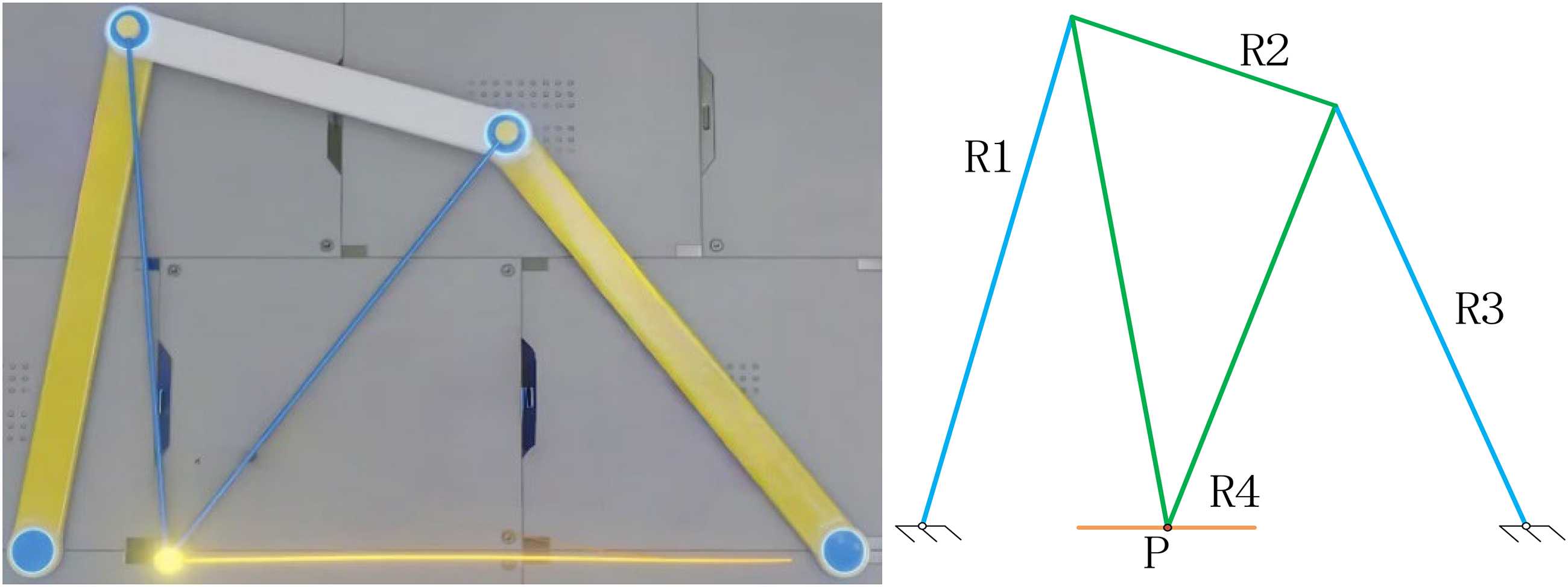
Schematic diagram of the Roberts mechanism. 59
Wan and Xu 47 obtained a new type of flexible linear guide mechanism by replacing the motion pair of the traditional rigid Roberts mechanism with a flexible hinge, as shown in Figure 33(a). A single Roberts mechanism can provide only single-point linear motion, so based on two flexible linear guide mechanisms, the XY compliance mechanism is designed in series, as shown in Figure 33(b). In addition, to construct a complete XY micropositioning platform, four such XY flexible mechanisms were used in parallel to form a 4-PP parallel mechanism, as shown in Figure 34. A novel adjustable demolding mechanism has been proposed that combines a Roberts connecting rod with an adjustable crank-rocker mechanism to accurately eject bolts of varying lengths in bolt cold-forging machines. The core design uses Roberts connecting rods to generate the straightest impact path rather than the traditional curved path and a crank-rocker mechanism to adjust the length of the connecting rods for continuous adjustment of impact force, avoiding collision noise between impact screws and pins. It is suitable for multistage cold forging production scenarios that require flexible adjustment of impact distance.
Upper and lower linear motion mechanisms. 47 (a) Flexible Roberts linear mechanism. (b) Two new Roberts flexible linear mechanisms.

XY micropositioning stage. 47 (a) Top view, (b) isotropic view and (c) side view.
Yu and Wu 48 proposed a new design of the adjustable strikeout mechanism, as shown in Figure 35. The linear motion path is achieved with Roberts connecting rods, designed for large strokes and high accuracy. The working principle is to replace the traditional rigid Roberts mechanism with a flexible blade spring to form a flexible linear guidance mechanism and to use parallel and series design to construct a two-layer symmetrical structural platform, using the pseudo-rigid body model (PRBM) for theoretical modeling, combined with finite element simulation to verify the performance. The experimental results show that the platform's working stroke in the X and Y directions exceeds 12 mm, the parasitic motion in the non-working direction is less than 1.7% of the working stroke and the cross-coupling error is less than 1.66%. The platform is suitable for scenarios that require a wide range of precise positioning, such as micro-coordinate measurement, MEMS processing and optical device adjustment, and its compact two-layer structure takes into account the balance of stroke and volume, but the dynamic performance (natural frequency of about 20 Hz) and assembly error still need to be further optimized.

Linkage mechanism utilizing the Roberts principle. 48
Chebyshev linear mechanism
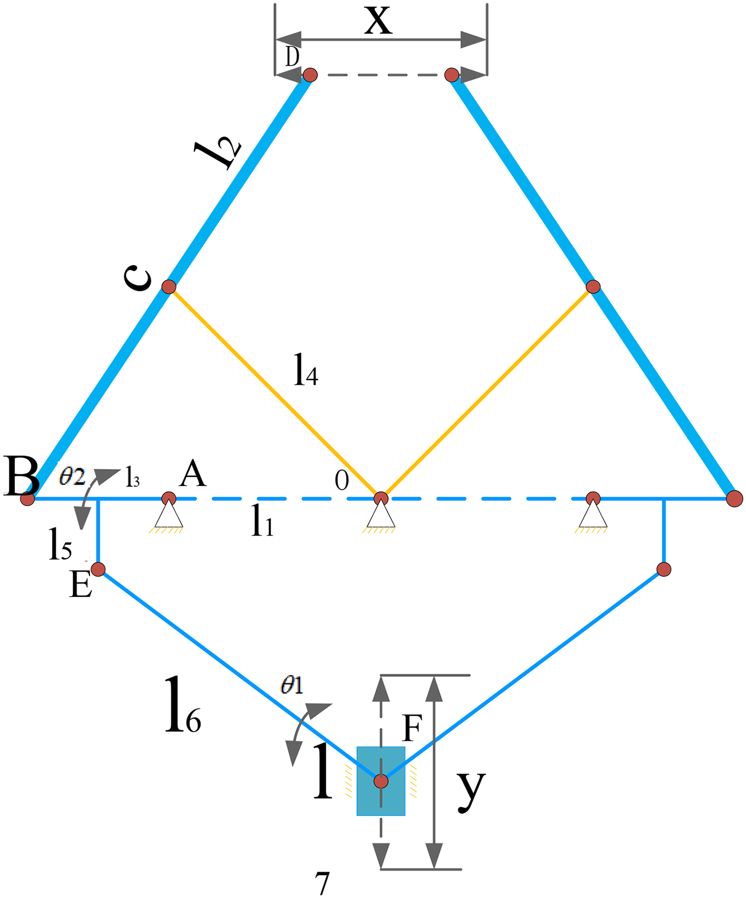
The Chebyshev mechanism is a special class of four-bar mechanisms. 49 As shown in Figure 36, in the Chebyshev four-bar linkage mechanism, rod 1 is designated as the active rod (driving rod), which rotates or swings under the drive of a motor or other power source. The remaining components connected to it (including frame rods, connecting rods and driven rocker arms) constitute the driven part (driven rod). Due to the fact that the entire mechanism is composed of four components connected by four typical rotating pairs (low pairs), according to the formula for calculating the DOFs of planar mechanisms, the Chebyshev mechanism has only one DOF. The Chebyshev linkage mechanism has significant advantages, such as an extremely simple structure (only four rods and four rotating pairs), low manufacturing and assembly costs and reliable motion, making it well suited to meet the planning requirements of many walking robots for foot-end motion paths. In the field of biomimetic robots, especially in the design of robots that mimic the gait of quadruped or bipedal animals, the Chebyshev mechanism has been widely and successfully applied. 50

Diagram of the connecting rod mechanism and its trajectory. 49
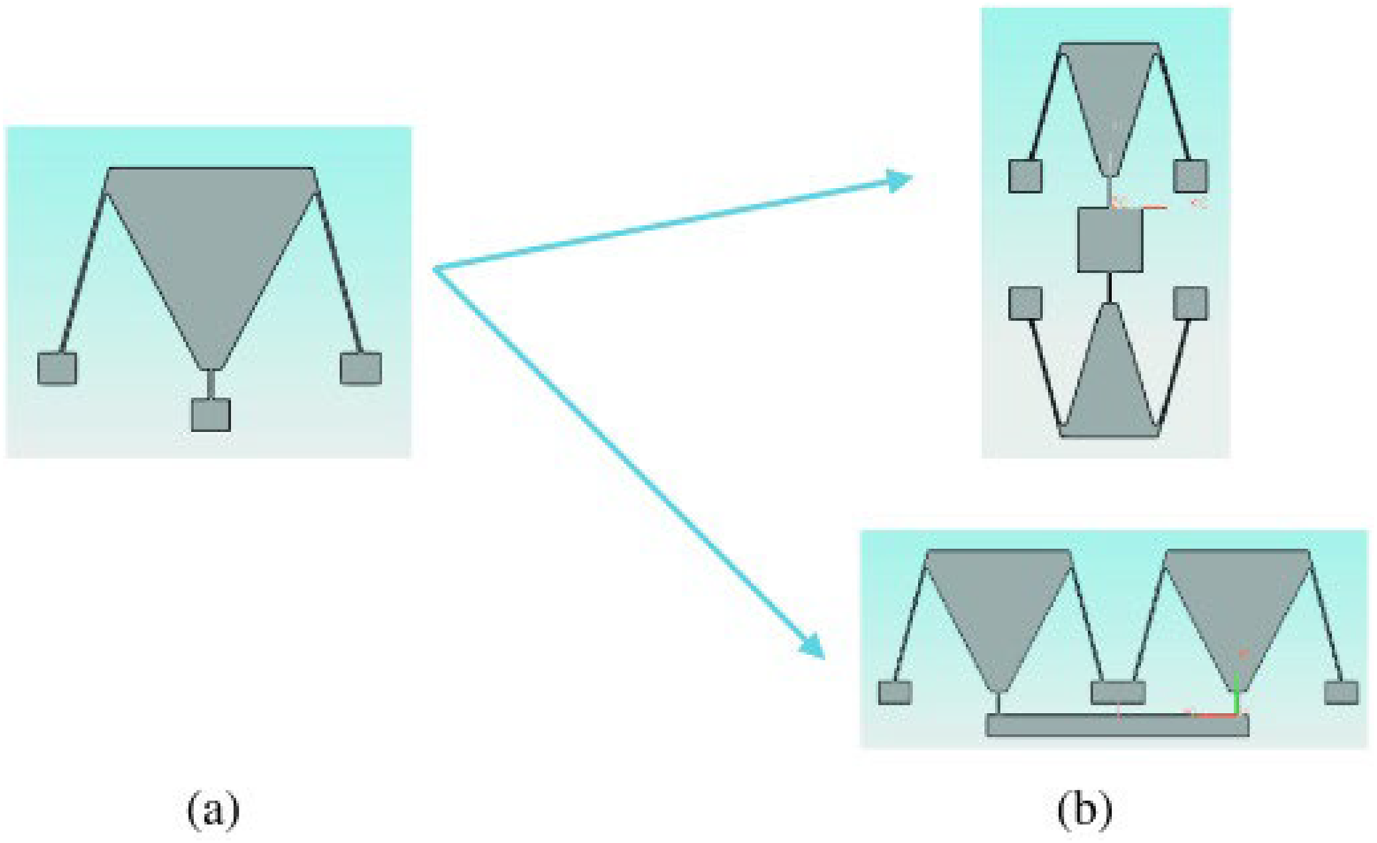
Shangqun Dong et al. 51 proposed a novel chain-legged insulator detection robot, as shown in Figure 37. The robot, based on the Chebyshev linkage design, is used to replace manual inspection of power insulator strings. The robot works in tandem with three identical climbing mechanisms, each of which uses two sets of Chebyshev connecting rods to achieve full-time, stable climbing and accommodate both vertical and horizontal insulator strings. The top of the building is designed as a flat surface, which is convenient for carrying cleaning, visual inspection, and other equipment; optimizes the movement path through trajectory planning; reduces speed fluctuations; and improves climbing stability. Laboratory prototype tests have shown that the robot can effectively complete insulator inspection and is suitable for complex environments that require regular maintenance, such as high-voltage transmission lines. The experimental results show that the newly designed chain-legged robot can successfully climb vertical and horizontal insulator strings and complete the detection task. The climbing process is shown in Figure 38.
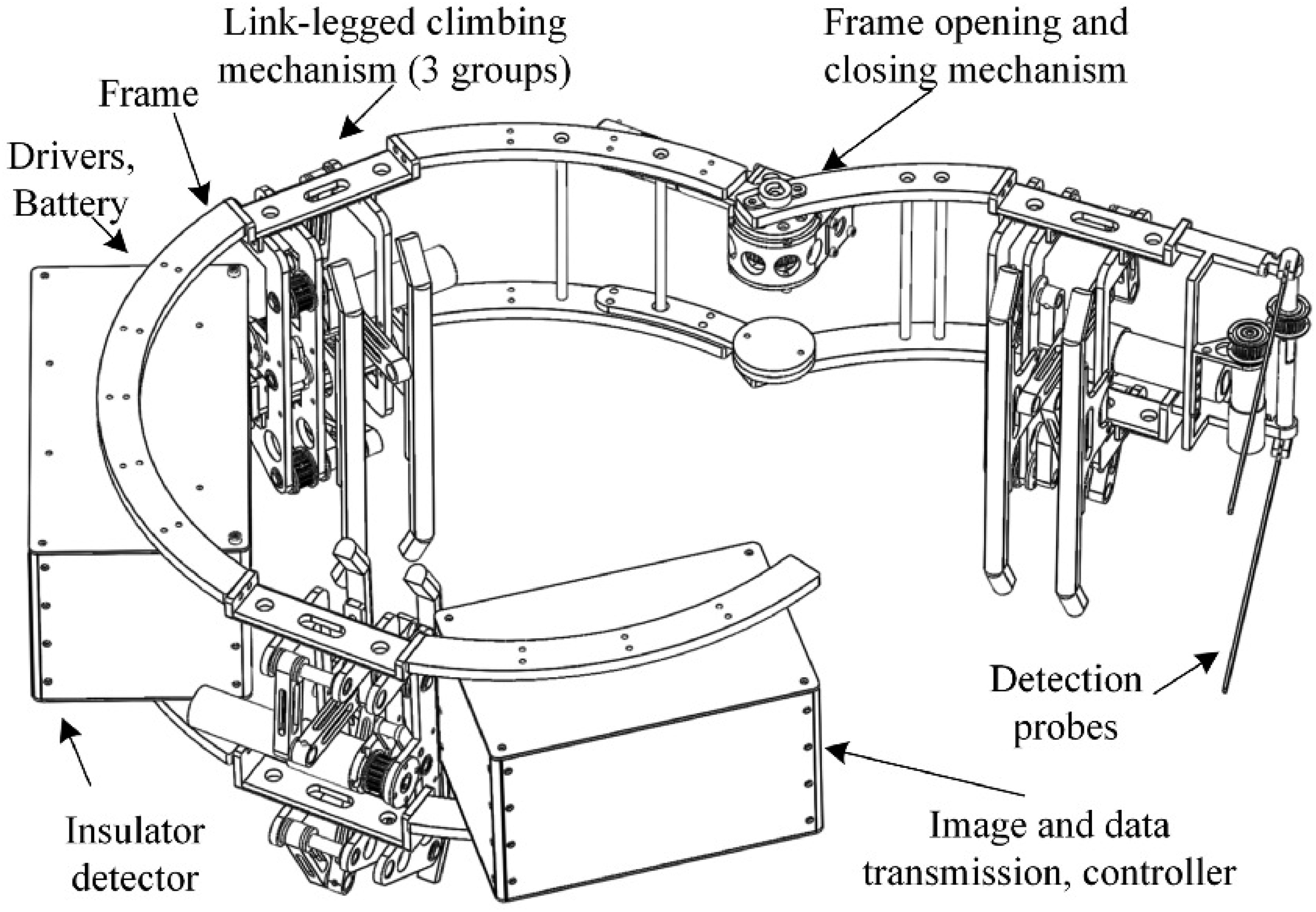
Detecting the structure of the robot. 51
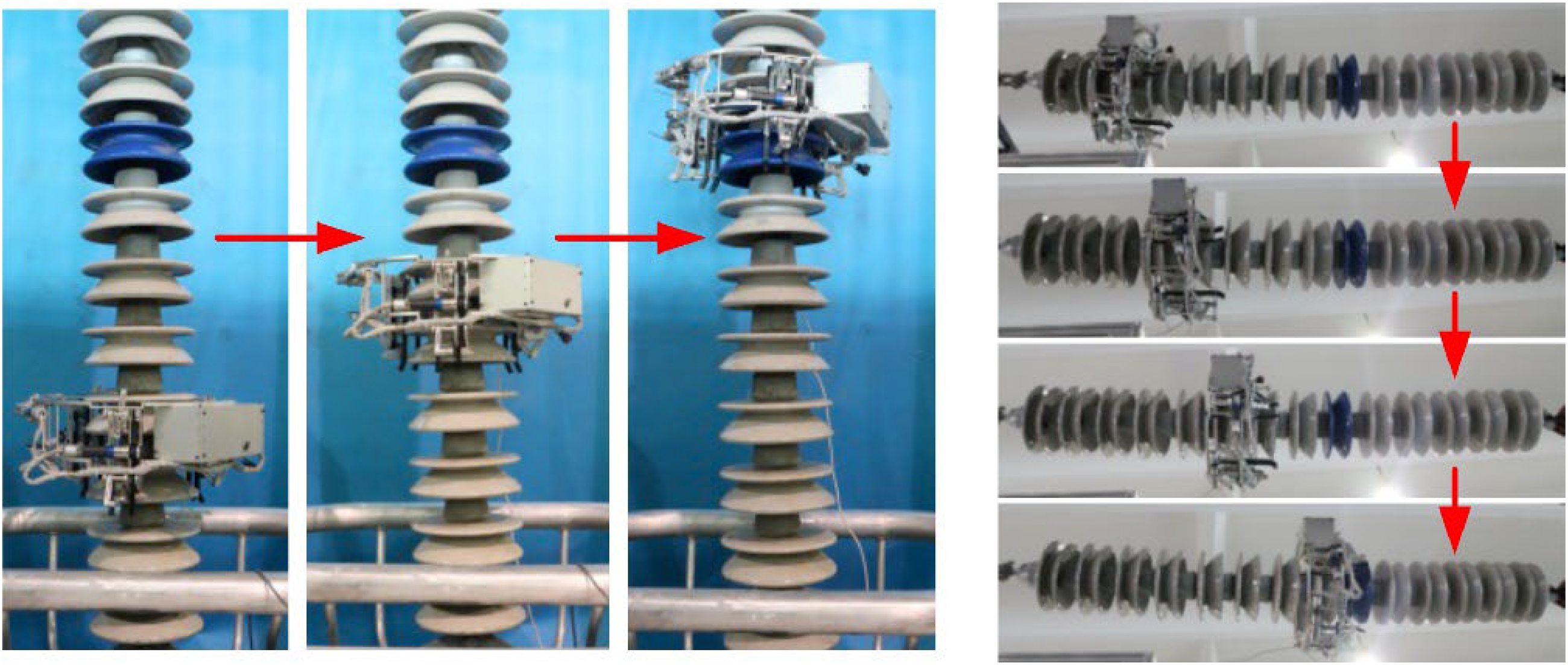
The process of climbing. 51
Xu Junjie and others, 52 to address the limitation of traditional fingers being unable to achieve linear translation of the distal knuckles in parallel and adaptive grasping modes, proposed a novel under-actuated robot hand (CLIS hand), as shown in Figure 39. It can implement under-driven grasping modes: linearly parallel grasping, in which the fingers move straight and parallel to each other, and self-adaptive grasping (LPSA), in which the fingers conform to the shape of the object. This article will describe only the linear kneading process of the distal knuckle using the Chebyshev linkage, a mechanical assembly that converts rotational motion into nearly straight-line movement: the second and proximal knuckles rotate under the drive of the first knuckle. Since the first knuckle, second knuckle, proximal knuckle, and base form the Chebyshev linkage, the distal joint moves in a straight line relative to the base. The distal knuckle, attached to the distal joint, moves in a straight line through the transfer of the empty distance (the gap before contact) and is kept in a fixed position using a double parallelogram gear mechanism until it touches the object. The entire gripping process is called “linear translation” (LT gripping) and is shown in Figure 40. Experiments show that the CLIS hand performs well at grasping flat objects in the LPSA gripping mode, and it offers broad application prospects due to its unique motion path and reliability.

Design of the overall structure of the CLIS finger. 52 (1) Pedestal, (2) proximal phalange, (3) distal phalange, (4) power plant, (5) first knuckle, (6) proximal joint, (7) third joint, (8) second joint, (9) idle-stroke transmission mechanism, (10) second knuckle and (11) distal joint. CLIS means using the design of Chebyshev linkage and air travel mechanism.

Linear translation and adaptive under-drive finger movements. 52
Hoekens linear mechanism
As shown in Figure 41, the Hoekens linkage mechanism consists of four rigid connecting rods: the fixed linkage OP (ground), the input linkage PQ (crank), the connecting rod QR and the rocker RO; the crank is the prime mover, and the point T on the connecting rod QR is the output point, which moves at an almost constant speed, and one of the segments of the trajectory is approximately straight line. 53 According to Kaneko et al., 54 only when the ratio of the maximum height deviation δ to the step size S of the linear trajectory at point T is less than 0.01 can the output trajectory of the connecting rod be considered to be a straight line.

Hoekens linkage mechanism. 53
V. Gopal et al., 55 to address the issue that a rigid connection mechanism can cause micro-objects to slide or slip during clamping and release in precision applications, designed a flexible micro-gripper with a Hoekens linear mechanism, as shown in Figure 42. The Hoekens linear mechanism was modified appropriately to achieve the parallel movement of the gripper, as shown in Figure 43. On the basis of the original Hoekens mechanism, additional connecting rods (L5, L6, L7) are added, which convert the linear displacement of the slider L7 into the angular displacement of L2 without relative motion between L and L5. The endpoint D of L3 in the modified Hoekens linear mechanism undergoes approximate linear motion over a limited range and serves as the gripper. The experimental results show that the gripper's performance is comparable to that of a traditional rigid-body connection mechanism. It also has potential application value in micro-object testing, fragile object handling and micro-component assembly.

Flexible micro-gripper. 55
Modified Hoekens linkage. 55
Jiwei Yuan et al. 56 proposed a novel deformable crawling robot for detection, search and rescue tasks in unstructured environments, as shown in Figure 44. The design inspiration for the robot legs comes from insects, which are designed as a multi-link structure, including Hoekens linkages and multiple parallel four-bar mechanisms. The special trajectory of the Hoekens linkage mechanism enables the robot to crawl on curved surfaces, including inner and outer arcs.

Structural model of the bionic robot. 56
A linear linkage mechanism is usually connected by some linkages, rotating pairs, motion pairs, etc. The number of basic components is small, the cost is low, the difficulty of manufacturing and assembly is low, and the expected motion trajectory and action can be stably achieved. For example, as a new type of deformable crawling robot based on Hoekens’ linear linkage mechanism, these derivative devices can be applied to various occasions and can have a significant role in packaging transportation, environmental investigation and medical and earthquake investigation.*****
Section 3 summary
The performance of the linear linkage mechanism is essentially determined by its structural topology and kinematic constraints, which pose core challenges for dynamic response and precision in guideless linear motion. The analysis in this section reveals that there is a clear binary opposition in its technical path: the precise linear mechanism represented by the Peaucellier–Lipkin and Sarrus mechanisms exchanges the complex multilink structure for the perfect track in theory, but its cumulative mass and low connection stiffness lead to the natural frequency of the system being often lower than 50 Hz, which fundamentally limits the dynamic bandwidth. For example, Watt, Chebyshev and other approximate linear mechanisms have achieved economy and reliability by virtue of their simplicity, but their inherent acceleration mutation of nonideal trajectory (straightness error is usually 0.1%–1% of the stroke) can easily induce vibration and impact.
In view of the above limitations, current optimization strategies, such as the use of lightweight materials, wear-resistant coatings, and gap-compensation structures, are mostly incremental improvements within the established structural paradigm. However, these measures have difficulty solving the essential contradiction between high dynamic requirements and structural complexity or between trajectory accuracy and manufacturing costs. Therefore, this section points out a more fundamental development direction: future innovation should go beyond the traditional purely rigid bar paradigm, explore the rigid–flexible hybrid configuration (leveraging the high-precision non-clearance characteristics of flexible hinges) or integrate with intelligent materials, and reconstruct the linkage mechanism at the transmission principle level. At the same time, the trajectory compensation algorithm is embedded in the real-time control system to form an intelligent connecting rod unit with “mechanical body drive control” integration, thereby breaking the performance bottleneck of its application in high-end equipment without significantly sacrificing its core advantage of having no guide rail.
The principle, advantages and disadvantages, and scope of application of the approximate linear motion mechanism are shown in Table 3.
Comparison of structures with approximate linear motion.

DOF: degree of freedom.
The basic n of high-precision linear feed mechanism
To achieve higher precision and performance in linear feed, this section introduces several types of high-precision linear feed mechanisms. Firstly, the actuators and their applications based on electrostrictive and magnetostrictive materials, as well as on direct-drive technologies such as linear motors and ultrasonic motors, were elaborated. Secondly, the system analyzed the design and characteristics of noncontact guiding mechanisms, including magnetic levitation, air static-pressure and liquid static-pressure guide rails. In addition, the principles and advantages of efficient transmission schemes, such as the nut-driven static-pressure screw, the double-nut-driven ball screw and the planetary roller screw, were explored, providing key technical support for the design of ultraprecision machining and measurement equipment.
The basic classification of direct-drive feed mechanisms
Actuators based on electrostrictive materials
Piezoelectric actuators utilize the inverse piezoelectric effect of piezoelectric materials to convert electrical energy into mechanical energy, achieving motion output. They are widely used in robotics, 57 precision instruments, 58 nanopositioning pltform, 59 multi-DOF pointing to the platform, 60 bioengineering and other fields. Piezoelectric drives have the advantages of having no electromagnetic interference, self-locking when power is off, simple structure, high resolution and wide temperature range. 61
In the field of micro-displacement actuators based on electrostriction, piezoelectric ceramics are a driving method with relatively mature applications and good resolution and dynamic response. Piezo-driven motion stages are used in a wide range of applications in precision operation, measurement and manufacturing.
Qin Haichen 62 designed a galvanic body printing platform, and its overall structure is shown in Figure 45, in which the macro-level drive uses a high-precision linear motion module to achieve the required wire-drawing speed for electrospinning. The microlevel drive uses a motion platform powered by piezoelectric ceramics to meet the process requirements for electric fluid jet printing. The maximum open-loop stroke of the microlevel motion platform is 340 340 340, the open-loop resolution is 0.5, and the maximum repeatability is 2 2 2. The system has a built-in high-precision capacitive displacement sensor with a resolution of 0.15 nm. Experimental results show that the proposed design method meets the control requirements for channel width in the manufacture of electric fluid jet printing.
The overall structure of the electroelectric fluid printing platform. 62 (1) Gantry arch, (2) micropositioning platform, (3) macro-drive platform, (4) marble base and (5) air floating vibration isolation platform.
Changjun Hu et al., 63 to solve the machining problem of complex-shaped micro parts, designed a micro-stamping device by leveraging the piezoelectric ceramic's characteristic of output displacement changing with input voltage. Its structure is shown in Figure 46. The actuator is made of laminated ceramic plates, with one end connected to the drive wire. The drive wire is then fixed within the cladding, and a fixed cover is installed at its end. The other end of the drive cable is connected to the controller. The displacement output shaft is fixed at the other end of the actuator, and the outer surface of the shaft is equipped with a linear bearing. The bell-shaped spring is installed between the end of the linear bearing and the actuator, and the other end of the linear bearing is fixed with a locking cap. There is a through-hole in the center of the lock cap, through which the output shaft passes. When a driving voltage is applied, the laminated piezoelectric actuator elongates, causing axial movement of the output. The physical object is shown in Figure 47.

Section of a linear inertial magnetostrictive actuator. 63 (1) Prestressing screw, (2) inertial mass, (3) permanent magnets, (4) magnetostrictive rod, (5) coil, (6) spring and (7) end effector.

Piezoelectric actuator for microgear hole punching. 63
In order to improve accuracy, precorrection instructions are compensated by a feedforward inverse model to counteract the nonlinearity of piezoelectric ceramics from the source; high-precision displacement sensors provide closed-loop feedback for real-time correction to suppress creep and interference; combining intelligent algorithms such as adaptive proportional–integral–derivative (PID) or neural networks enhances the robustness of the system under complex operating conditions; and these are supplemented by driving waveform optimization to suppress vibration and temperature monitoring compensation to ensure long-term stability. Through the synergistic effect of these strategies, a leap from being able to move to being able to stably and precisely process complex micro parts can ultimately be achieved.
Actuators based on super magnetostrictive materials
Giant magnetostrictive material (GMM) is a new type of smart material that is deformed by an external magnetic field. Its magnetization changes with applied force; offers noncontact drive, rapid response and high energy density; and is widely used in precision drives, sensors and other fields. 64
Actuators based on super magnetostrictive materials (giant magnetostrictive actuators (GMAs)) can obtain good displacement accuracy in a wide range of strokes and have shown great application potential in ultraprecision machine tools, industrial robots, micro motors, aerospace, chemical machinery, petroleum and marine engineering and other fields due to their low wear, long life, high power density and good dynamic response performance. 65 However, the hard and brittle characteristics of the super magnetostrictive material itself lead to its processing difficulty, low efficiency and low resistivity, resulting in significant eddy current loss during operation, and it is difficult to reduce its heat generation, so the thermal expansion and contraction of the resulting mechanism limit the further improvement of the displacement accuracy of this kind of mechanism. 66
Bintang Yang et al. 67 designed a new clamping mechanism based on a GMM, which changes shape when exposed to a magnetic field, for heavy-duty, precise positioning of linear stepper motors. The structure and prototype photos of the clamping mechanism are shown in Figure 48. The institution utilizes the expansion and contraction characteristics of GMMs under the influence of a magnetic field to achieve clamping and releasing by controlling the field's direction and strength. The core of this mechanism is preloading and magnetic field control, ensuring that the clamping state can be maintained even without power and making it suitable for high-precision, heavy-duty linear motor applications.

Structure diagram of clamping mechanism. 67 (1) force; (2) guideway; (3) ball bear; (4) housing; (5) permanent magnet; (6) coil; (7) solenoid pick-up; (8) Belleville; (9) outlet. GMM: giant magnetostrictive material.
Guangming Xue et al. 68 designed a magnetostrictive actuator (GMA) to meet the control requirements of high-pressure common rail injectors. Its core converts the stretching motion of the magnetostrictive rod into the shortening motion of the actuator through a specially designed output rod to adapt to the working characteristics of the normally closed fuel injector. This actuator relies on the “magnetic field deformation” direct conversion characteristics of magnetostrictive materials, combined with experimentally validated displacement models and optimized driving voltage waveforms that can suppress displacement fluctuations, to achieve millisecond-level fast response and high-precision control with low residual displacement. The actuator is shown in Figure 49. Therefore, this actuator is not only suitable for high-pressure common rail fuel injection systems in diesel engines (including passenger cars, commercial vehicles, and engineering equipment), but its excellent performance characteristics have also made it widely used in engineering applications.

The working principle of high-pressure common rail injector. 68 (1) Outlet chamber, (2) fuel outlet, (3) guide rod, (4) needle valve matching parts, (5) pressure chamber, (6) steel ball, (7) control chamber, (8) fuel inlet, (9) spring and its seat and (10) storage chamber.
Due to deformation driven by the GMM under a magnetic field, the dynamic characteristics of the magnetostrictive actuator (GMA) are affected by hysteresis, resulting in displacement hysteresis. The thermal effect is caused by eddy currents and hysteresis losses, leading to deformation of the GMM rod. Hysteresis modeling and adaptive control, combined with a heat sink/cooling channel and a low-eddy current coil design, can suppress adverse effects.
Linear motors and ultrasonic motors
The motion of a linear motor is along a straight line, unlike a rotary motor, which requires a threaded transmission device. A linear motor is derived from a rotary motor. The linear motor is formed by cutting the rotating machine along its cylindrical radial cross section and spreading it into a planar structure, as shown in Figure 50. It can be seen that the coil windings are stator and fixed in the rotating motor structure, whereas in the linear motor structure, they are primary and can move relatively. The primary or secondary of the linear motor is fixed, the secondary or primary is moved, and the free movement is realized, which is applied to various occasions of the precision workbench system. 69
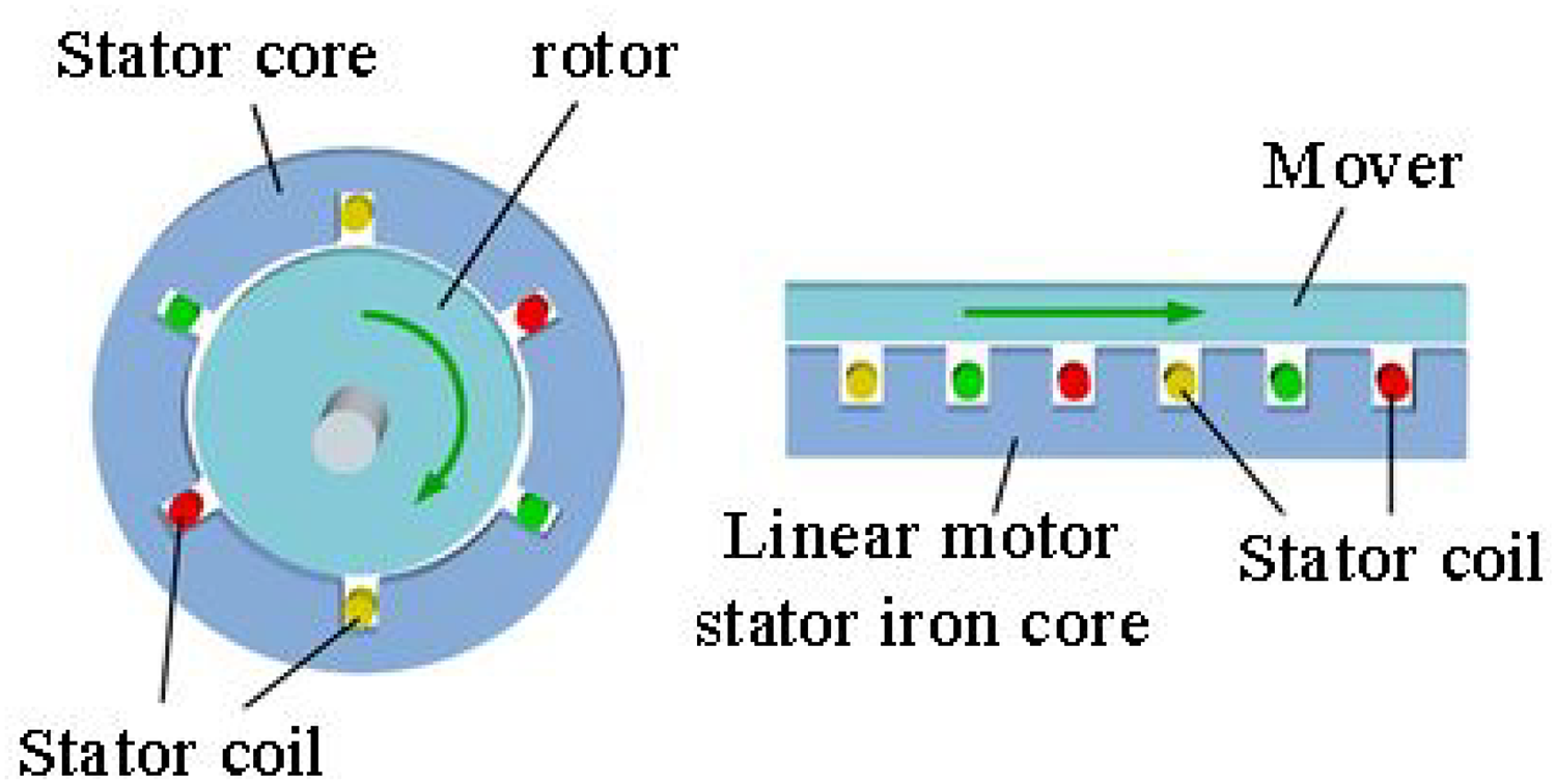
Origin of flat-plate-type linear motors. 69
Yu et al. 70 proposed a dual linear motor differential-drive micro-feed servo system, with the transmission mechanism shown in Figure 51. Two types of high-speed “macroscopic movements” that operate above the critical crawling speed are achieved by using the differential speed of the upper and lower linear motors to eliminate the low-speed nonlinear crawling phenomenon inherent to traditional electromechanical servo systems and to achieve precise micro-feed control. The simulation results show that, under both constant and variable-speed conditions, the dual linear motor differential drive servo system is significantly better than the linear motor single-drive system for low-speed micro-feed.
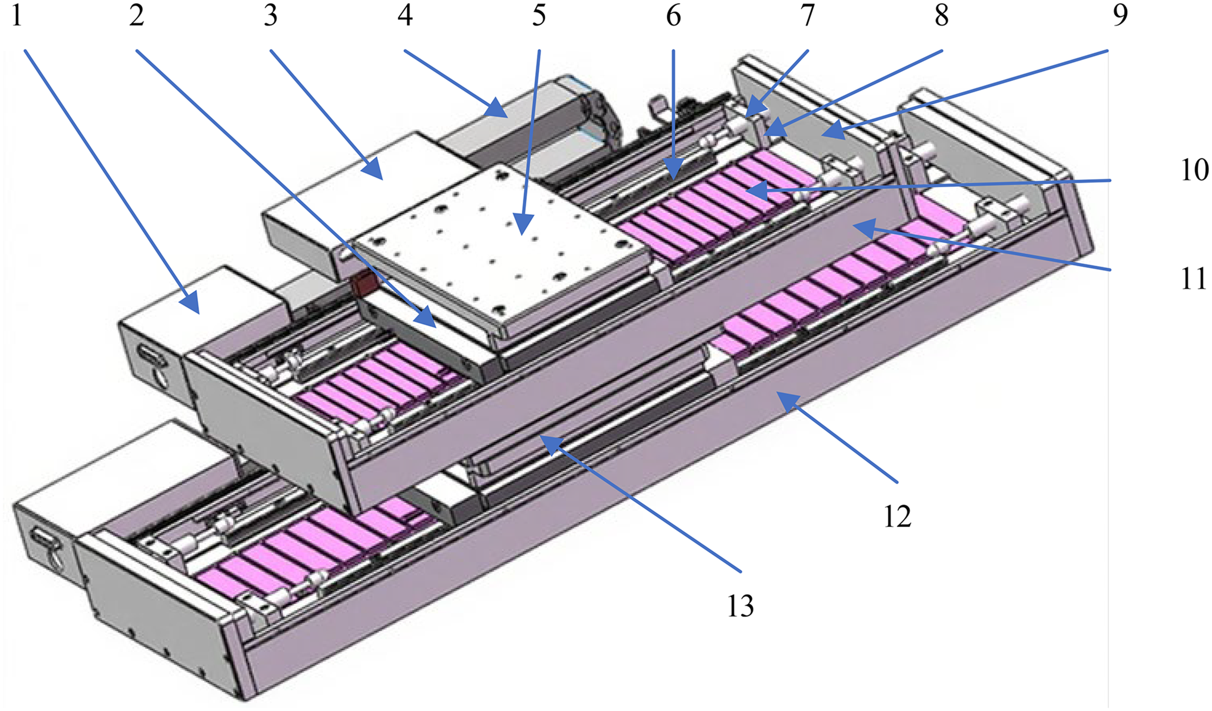
Differential drive precision transmission mechanism of dual linear motors. 70 (1) Fixed end of upper linear-motor drag chain, (2) upper linear-motor actuator, (3) moving end of upper linearmotor drag chain, (4) upper linear-motor drag chain, (5) upper linear-motor table, (6) linear guide rail, (7) proximity switch, (8) mechanical limit block, (9) upper linear-motor end cover, (10) upper linear-motor stator, (11) upper linear-motor assembly, (12) under linear-motor stator and (13) under linear-motor actuator.
The structural layout of the cylindrical linear motor has evolved from the traditional rotating motor, and the radial expansion of the latter has resulted in a flat-plate permanent-magnet synchronous linear motor. Then, the cylindrical permanent-magnet synchronous linear motor can be obtained by winding it axially into a circular shape. 71 The conversion process is shown in Figure 52. This structure has significant advantages in compactness, as its symmetrical cylindrical geometry (circular structures of equal size around its axis) effectively eliminates the inherent lateral edge effects in the motor. These edge effects refer to the uneven forces or magnetic fields at the edges of flat motors. By reducing these, the design typically provides a more uniform distribution of magnetic flux density (meaning that the magnetic force is evenly distributed throughout the entire cylinder) and achieves higher space utilization. At the same time, the cylindrical rotor or stator (respectively the rotating or stationary part of the motor) can serve as a natural guiding mechanism, which not only simplifies the design complexity of the support and guiding system but also significantly improves the overall mechanical stiffness (deformation resistance), effectively suppresses vibration and noise during operation and comprehensively improves the dynamic performance and smooth operation of the system. Cylindrical linear motors are suitable for applications that require compact space and high-precision linear motion (linear motion), such as positioning or propulsion mechanisms in precision instruments and medical equipment. They are also commonly used in applications that require high response speed (rapid motion changes) and uniform thrust (one effort), such as automatic small conveyors and small aerospace drives.

Conversion process of a cylindrical linear motor. 71
Because linear motors directly generate linear motion, their dynamic characteristics are affected by thrust fluctuations from end effects, leading to motion errors. The thermal effect comes from stator thermal deformation caused by coil electrification and heating. By optimizing the coil layout to reduce end effects, combined with precision compensation via water/air cooling systems and thermal imaging feedback, operational stability can be improved.
Table 4 summarizes the principle, advantages and disadvantages, and application scope of the linear drive feed mechanism.
Comparison of three types of linear drive structures.

GMA: giant magnetostrictive actuator; GMM: giant magnetostrictive material.
Static-pressure guide rail linear mechanism
Magnetic levitation feed mechanism
Jun Zheng et al. 72 invented a magnetic levitation mechanism. The hybrid magnetic levitation mechanism adopts a linear induction motor as the transmission mode, combined with permanent magnetic levitation (PML) and superconducting magnetic levitation (SML) to achieve a manned operation. SML provides high-precision passive stability, with a suspension height variation of ±1 mm or less and excellent lateral offset control. PML bears the main load and is suitable for medium- and low-speed maglev transportation systems, with a rated load of 375 kg. The system coordinates the stiffness difference between the two via vertical linear sliders and offers good dynamic and static stability, making it suitable for preset magnetic track environments such as urban rail. The principle of the maglev feed mechanism is shown in Figure 53.

Model diagram of a magnetic levitation feed mechanism. 72 PM: permanent magnet; YBCO: yttrium barium copper oxide.
Tang et al. 73 designed a maglev conveyor based on multiple control strategies; the overall structure is shown in Figure 54, and the mechanism is composed of a maglev unit, a mechanical frame and a control system of four units of collaborative mechanism, wherein the permanent magnet provides the basic levitation force for the maglev unit and the electromagnet dynamically adjusts the suspension gap, so as to achieve nanometer-level displacement accuracy. The transport vehicle moves synchronously through four suspension units, and the PID control synchronization error is less than 0.05 to ensure that the vehicle body moves horizontally. When the load changes, the electromagnet can control the current in real time to prevent large fluctuations in displacement and maintain suspension stability.

Overall structure of magnetic levitation. 73
The noncontact transmission principle of the magnetic levitation mechanism eliminates mechanical friction, reducing wear to almost zero and greatly extending service life, while avoiding the thermal deformation problem caused by friction in traditional transmissions and improving thermal stability. At the same time, the magnetic levitation mechanism can quickly restore stability when the load changes, reflecting the decisive role of the driving mode in dynamic response and anti-interference ability. In addition, since there is no need to overcome static friction, power consumption is more favorable under light-load conditions, and the four-unit collaborative mechanism indicates that the driving principle directly affects the upper limit of load capacity (e.g. 120 kg). These characteristics collectively determine the system's applicability in clean environments, high-load precision transportation and other scenarios.
Design of high-precision air static-pressure guide rail
Haiyang 74 proposed a design of a high-precision air static-pressure guide rail. When a certain pressure of air enters the flow field, pressure is generated on the wall. The air static-pressure guide rail uses this principle to provide high-pressure air of 0.4 to 0.7 MPa from an external air source. The gas enters the flow field through the inner hole of the guide rail component through a throttle valve, disperses into the surrounding environment around the throttle hole and then continuously discharges into the atmosphere from the outlet at the edge of the flow field. The wall pressure applied by high-pressure air will also decrease from the throttle valve towards the surroundings until it reaches the external atmospheric pressure. The vertical wall pressure, which balances the support force of the guide rail and gravity, causes the guide rail to float, and the wall pressure generated by the side flow field limits its displacement in the left and right directions. Its structure is shown in Figure 55.

Design diagram of an air static-pressure guide rail scheme. 74
The design of the aerostatic guide rail is not in direct contact with the guide rail, and the friction is very small, so it has the properties of high precision and high stability, the driving power required by the structure is small, the movement efficiency is high, the air is used as the medium, it will not leak and pollute the environment like lubricating oil, and it is often used in the occasion of high cleanliness and has high application value in the field of ultraprecision machining.
Design of three-wire slot self-compensating liquid static-pressure guide
Chen et al. 75 proposed a design for a three-wire slot self-compensating static-pressure guide rail to improve the machine tool's machining accuracy by optimizing the oil film stiffness. Figure 56 shows the schematic diagram of the support principle structure of the three-wire slot self-compensating static-pressure guide rail. Its working principle is to apply hydraulic Ohm's law and flow conservation conditions to adjust the hydraulic resistance at the throttling clearance by displacing the slider, thereby compensating for load changes and improving the stiffness and stability of the guide rail. The guide rail is suitable for precision and ultraprecision machine tools, especially in places that require high stiffness and high motion accuracy. The upper and lower support oil chambers of the three-wire slot self-compensating static-pressure guide are equipped with throttling islands that are at the same height as the oil seal edge. There is an oil supply chamber in the middle of the throttling island, which is symmetrically arranged with the oil collection chambers on both sides. The throttling edge is located between the oil supply chamber and the oil collection chamber. As shown in Figure 57, the upper oil collection chamber is connected to the lower support oil chamber through a feedback channel, and the lower oil collection chamber and the upper support oil chamber are also connected through a feedback channel.

Design principle diagram of three wire slot static-pressure guide rail. 75 (1) Upper oil collection chamber, (2) upper support oil chamber, (3) upper sealing oil edge, (4) feedback flow channel, (5) lower sealing oil edge, (6) oil supply flow channel, (7) lower oil supply chamber, (8) lower oil collection chamber, (9) lower support oil chamber, (10) the lower throttle edge, (11) the upper oil supply chamber and (12) the upper throttle edge.
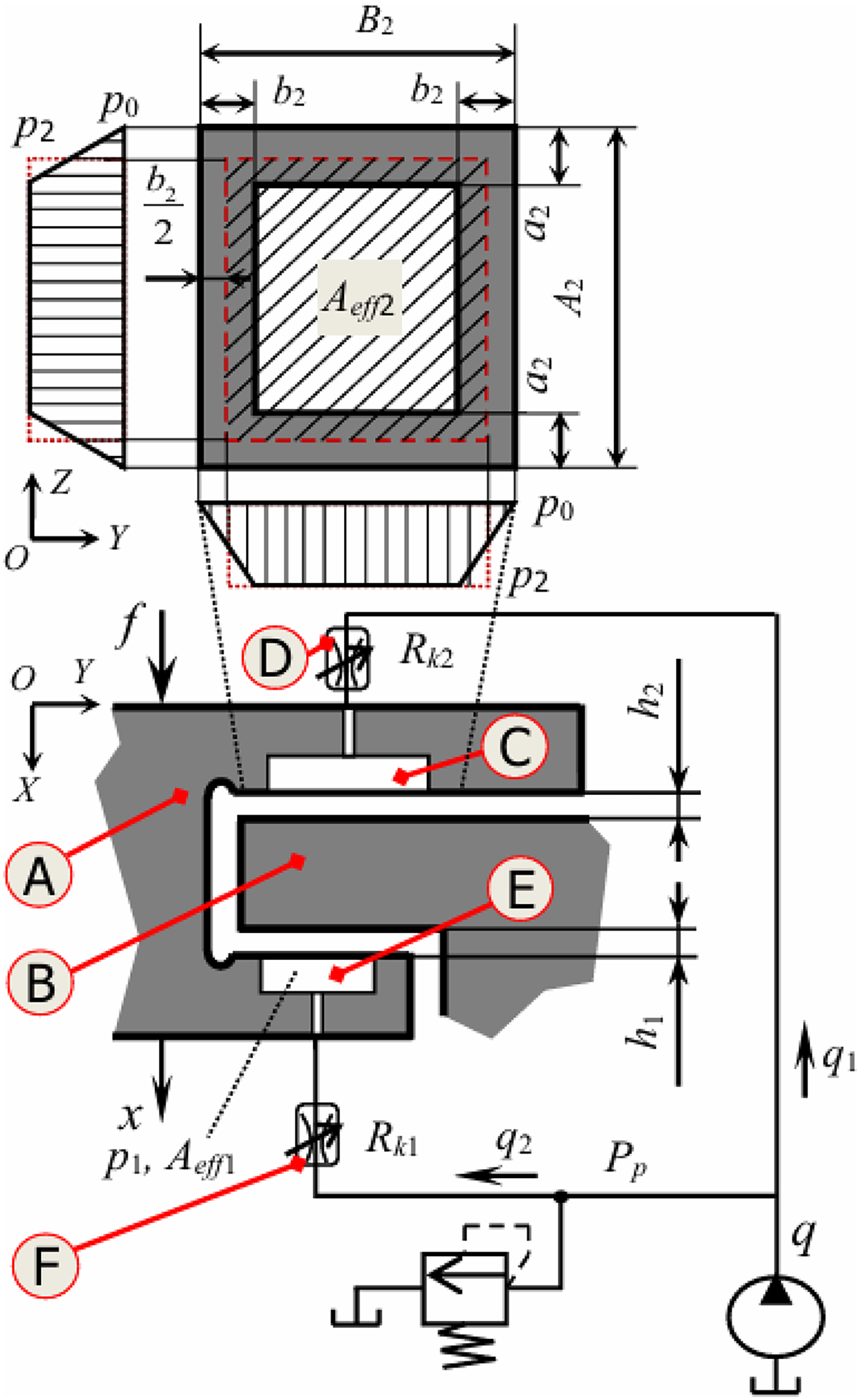
Schematic diagram of a static-pressure guide hydraulic system. 75
The three-wire slot-type self-compensating static-pressure slider has four identical support oil chambers on the upper, lower, left and right sides. The upper, lower, left and right oil supply chambers are respectively connected to the inlet holes of the upper and lower oil supply chambers and to the left and right oil supply chambers on the upper surface of the slider, via flow channels on the slider. As shown in Figure 58, taking the upper and lower support surfaces of the slider as an example, the lubricating oil in each oil supply chamber enters the oil collection chamber on the same side through the throttling pressure of the throttle valves on both sides of the oil supply chamber, the upper surface of the bottom plate and the lower surface of the upper guide rail, forming a gap. Then, it enters the corresponding support oil chamber through the feedback channel set in the slider, flows through the oil seal edge of the slider and the oil outlet gap formed by the lower surface of the bottom plate and the upper surface of the upper guide rail, enters the bottom-plate recovery groove and finally flows into the hydraulic station through the return pipe for recovery and reuse, as shown in Figure 59.

Schematic diagram of a three-dimensional structure of liquid static-pressure guide rail. 75 (1) Sliding block, (2) oil inlet block, (3) buffer installation board, (4) upper guide rail, (5) buffer, (6) guide rail side strip and (7) bottom plate.

Schematic diagram of three wire slot static-pressure slider structure. 75 (1) Left and right oil inlet holes, (2) upper and lower oil inlet holes, (3) upper throttling edge, (4) upper oil supply chamber, (5) upper support oil chamber, (6) right support oil chamber, (7) upper oil collection chamber, (8) right fuel supply chamber and (9) right oil collection chamber.
Compared with ordinary hydraulic guide rails, it has greater bearing capacity, has three trunkings, can evenly distribute the pressure oil film over a large area, can withstand heavy loads and is suitable for heavy-duty applications, offering great prospects in high-end machine tool manufacturing and aerospace and other fields.
Design of liquid hydrostatic guide rail
As shown in Figure 60, the static hydraulic fluid exerts pressure on the narrow spacing (clearance) between the moving pair of components through the hydraulic station. This creates a supporting oil film with specific load-bearing capacity and stiffness, completely separating the moving parts and preventing direct metal-to-metal contact. This process provides stable fluid lubrication and precise linear motion guidance. A “static-pressure bearing” is a device that uses external hydraulic pressure to generate a load-carrying oil film between two surfaces, rather than relying on movement to generate pressure. A “static-pressure guide rail” refers to a guiding mechanism that uses this bearing principle to support linear movement. Such guide rails are noted for their high motion accuracy, strong load-bearing capacity, low friction, long service life and ability to maintain accuracy over time, making them widely used in precision and ultraprecision machine tools. 76

Three-dimensional structural design diagram of a static-pressure guide rail. 76
Design of constant-current static-pressure guide rail
Yang and Chen 77 calculated the flow rate of the static-pressure chamber, and a hydraulic system with an open, constant-flow static-pressure guide rail was designed, as shown in Figure 61. Starting with the working principle of the static-pressure guide rail, the design and theoretical calculations for the constant-current and constant-pressure guide rails are introduced. A constant-current static-pressure guide rail is a technology that forms a stable oil film gap between the guide rail and the static-pressure chamber by supplying hydraulic oil at a constant flow rate. Its working principle is to utilize the incompressibility and constant flow rate of liquids to automatically adjust the oil film clearance in response to changes in external loads, thereby maintaining high stiffness and stability. Compared with constant-pressure and static-pressure guides, constant-current guides have greater overload capacity, antipollution performance and adaptability, making them suitable for high-precision machining equipment such as large CNC machine tools. Its high measurement accuracy and small variation in oil film clearance can effectively reduce friction and vibration, improve machining quality and increase load-bearing capacity. The application scope includes large machine tools that require high precision, stability and heavy-duty conditions, such as CNC gantry milling machines.

Structural diagram of an open-type constant-current static-pressure guide rail. 77
The constant-flow hydrostatic guide table offers more stable, accurate operation due to its lower friction, self-lubrication and moderate vibration absorption. Within a certain range, due to the liquid's incompressibility and the constant flow input, the oil film gap has high stiffness, which has little effect on changes in the external load. Therefore, the use of a constant-flow hydrostatic guide rail workbench can not only increase the worktable's bearing capacity but also improve processing quality.
Design of nut-driven static-pressure screw
Yandong 78 invented a static-pressure bearing. The core principle is to form a rigid oil film under constant pressure between the threaded engagement surfaces of the screw and nut via an external oil supply system, thereby completely separating the two metal parts and achieving pure liquid friction. This noncontact transmission method fundamentally eliminates crawling, enabling extremely smooth, continuous low-speed motion. Its positioning accuracy can reach submicron or even nanometer level, making it particularly suitable for heavy-duty, ultraprecision machine tools and measuring equipment. In terms of thermal stability, the effective suppression of frictional heat by the oil film and the circulating cooling effect of the pressure oil keep heat generated by the system to a minimum, allowing it to be quickly carried away and significantly reducing thermal deformation, ensuring accuracy and stability under long-term operation. In terms of dynamic stability, the high-stiffness oil film provides excellent damping, effectively suppressing vibration and impact loads, ensuring excellent motion stability and dynamic response performance under heavy, variable-load conditions. This is suitable for fields with extreme requirements for stability, accuracy and load-bearing capacity, such as ultraprecision machine tools, large telescopes, semiconductor manufacturing equipment and precision actuation systems in the aerospace industry. The overall structure is shown in Figure 62.

Feeding system based on DDHSNP. 78 DDHSNP is the core object of research in this doctoral thesis, representing a dual drive liquid hydrostatic screw pair micro feed system.
The stability of the nut-driven static-pressure screw is the key to achieving ultrahigh precision. In terms of thermal stability, the core challenge is thermal deformation caused by oil film shear friction, particularly thermal elongation of the screw, which can directly lead to significant positioning errors. At the same time, the increase in oil temperature will reduce the oil film's stiffness. The solution mainly relies on an efficient temperature control system (such as hollow cooling of the screw) and thermal error compensation technology. In terms of dynamic stability, the greatest risk is oil film oscillation, a self-excited instability unique to static-pressure supports, which can lead to severe vibrations. At the same time, it is necessary to avoid resonance in the system structure. The stability guarantee lies in optimizing the throttle design to suppress oil film turbulence and in improving the natural frequency through a well-designed structural dynamics. Ultimately, the stability analysis of the structure must be treated as a systematic problem of electromechanical hydraulic coupling, requiring careful consideration of interactions among the thermal, flow and structural fields to ensure stable, reliable operation in precision applications.
Design of feed system for double-nut-driven ball screw pair
Shigang 79 summarized the design advantages of the predecessors and proposed a double-nut-driven ball screw auxiliary feed system, as shown in Figure 63. In this new mechanism, the drive nut assembly uses internal circulation, ensuring a smooth, runout-free movement of the rolling elements. The drive nut is connected to a contact-free ball bearing, and the nut assembly is easy to machine. Double-nut preload eliminates axial clearance.

Model diagram of a double-nut-driven ball screw. 79
Double-nut preloading eliminates axial clearance, enabling reverse-positioning accuracy within ±2 μm. The preload from the double-nut structure increases contact stiffness and enhances axial rigidity by 30%–50%. This shared double-nut structure can also withstand a larger load. However, excessive preload may lead to higher friction and a temperature rise, and there are strict requirements for installation accuracy. Despite these limitations, the structure is suitable for high-precision, heavy-duty automation equipment.
Because the double-nut-driven ball screw pair eliminates axial clearance through double-nut pre-tightening, the dynamic characteristics are affected by the difference in synchronization between the double nuts, leading to vibration. The thermal effect arises from the heat generated by pre-tightening friction, which leads to component deformation. Through dual-motor synchronous control and pre-tightening force adjustment, combined with the cooling system and thermal error compensation, the accuracy can be guaranteed.
Design of planetary roller screw
As a transmission mechanism that converts rotary motion into linear motion, the planetary roller screw has the advantages of high transmission accuracy, strong bearing capacity, high running speed and high efficiency, and its comprehensive performance is superior, and it has been gradually used in aerospace, CNC machine tools, medical equipment, weapons and equipment, and other occasions with high comprehensive performance requirements.
Zhifeng et al. 80 conducted an angular velocity analysis of the planetary roller screw according to the principle of planetary motion, yielding angular velocity relationships among the components. Secondly, based on the principle of spiral transmission, the relationship between the thread direction and the number of planetary roller screw heads, as well as the lead calculation formula, was derived. Then, based on the thread parameters, the conditions the gear parameters must meet are determined. Then, based on the thread parameters, the conditions required for the number of rollers and the roller assembly relationship were analyzed. Finally, the roller's rolling state is determined from the roller's force. The structure is shown in Figure 64.

Three-dimensional design diagram of a planetary ball screw. 80
Section 4 summary
Section 4 systematically elaborates on the two core technological paths for high-precision linear feed: direct-drive and static-pressure guidance mechanisms. Its core lies in breaking through the bottlenecks of traditional mechanisms in accuracy, rigidity and dynamic response by eliminating intermediate contact links in the mechanical transmission chain. The performance of these institutions heavily relies on key indicators such as thermal stability, dynamic response and energy efficiency. Linear motors can achieve acceleration of up to 10 G and control bandwidth exceeding 500 Hz, but their force constant thermal drift can reach 0.1%/°C, requiring efficient cooling systems to maintain stability. Piezoelectric ceramics and magnetostrictive actuators have subnanometer resolution, but there are issues with hysteresis nonlinearity ranging from 10% to 15% and energy conversion efficiency below 5%. In the static-pressure support technology, the damping of the air static-pressure guide rail is low due to the compressibility of the medium, and the frequency response is mostly between 10 and 50 Hz. Although the dynamic stiffness of the hydrostatic guide rail is higher and the frequency response can reach over 100 Hz, it requires extremely high stability of the oil temperature, which needs to be controlled within ±0.5 °C, and its hydraulic system energy consumption can account for 30% of the total system power consumption.
These precise data point to a conclusion: achieving high performance no longer depends on the innovation of a single component, but on the collaborative design of the “electromagnetic thermal fluid structure” strong-coupling system. Therefore, future breakthroughs in this field will depend on the model-based design paradigm. This requires us to establish a high-fidelity multi-physics field coupling model for virtual optimization, develop intelligent control algorithms that integrate physical knowledge to compensate for nonlinearity and disturbance and ultimately promote the evolution of high-precision feed system from a precision “actuator” to an “agent” with global perception and precise regulation, laying a solid theoretical and technical foundation for the next generation of ultraprecision equipment.
Table 5 summarizes the principles, advantages and disadvantages, and applicable scope of the static-pressure guide rail and some other transmission mechanisms in the article.
Comparison between static-pressure guide rails and other transmission mechanisms.

CNC: computer numerical control; EM: electromagnetic.
Some new linear feed mechanisms
This section focuses on cutting-edge developments in linear feed technology and introduces a series of innovative linear feed mechanisms. The working principles and technical characteristics of various planar motors, including magnetic levitation, dynamic permanent-magnet synchronous and high-temperature superconducting planar motors, were analyzed in detail. At the same time, it also covers novel configurations such as micro-feed platforms based on microelectromechanical systems, cam mechanisms for linear intermittent feed, rod-type linear motors and dual-stator planar motors. These institutions have demonstrated enormous potential for applications in high-end fields such as semiconductor equipment, precision instruments and robots, representing an important direction for the development of linear drive technology.
Planar motor
A planar motor is a device that directly converts electrical energy into two-dimensional planar translational motion, without the need for complex mechanical transmission, and achieves motion control via electromagnetic induction. It is widely used in industrial automation, robotics, aerospace and other fields, especially for high-precision, high-speed and harsh-environment two-dimensional motion control. Its advantages include a simplified device, no mechanical contact, low noise, good heat dissipation, etc., but it has disadvantages such as low efficiency and power factor at low speeds and high requirements for linear guides. 81
The realization of high reliability of planar motors relies on strict control of several key factors. In terms of long-term operational stability, the lack of contact between the rotor and stator prevents mechanical wear, theoretically resulting in an extremely long mechanical lifespan. The failure rate is usually closely related to electromagnetic thermal management. If the Joule heat generated by continuous coil electrification is not effectively dissipated, it can lead to insulation aging, magnet demagnetization and, subsequently, performance degradation or even sudden failure. The core of its assembly lies in establishing a high-precision benchmark, which requires precision instruments, such as laser interferometers mounted on a leveled base to ensure a uniform air gap between the rotor and stator, and strict calibration of the parallelism between the position sensor and the guide rail. Finally, an error compensation table is generated via full-stroke calibration. To improve reliability, redundant position sensing, forced liquid-cooling systems, and model-based health-status monitoring and predictive maintenance strategies are often used in design.
Magnetic levitation planar motor
The mover of the magnetic levitation planar motor is a permanent magnet. The stator contains six-dimensional drive coils. When energized, these coils generate a magnetic field that levitates the mover. The motor consists of a six-DOF mover and stator module. Each mover is independently controllable in six DOFs. Its accuracy reaches the nanometer level. A product from a foreign company achieves registration accuracy of less than 5 μm. 82 It can achieve 60-pm positioning in ASML equipment and, when equipped with a detection mechanism, can meet high-end requirements. It is suitable for semiconductor ultraprecision workpiece stages, such as ASML's NXT and NXE series lithography equipment and high-end probe testing systems. Its advantages include a simple structure, high speed and acceleration, high precision, maintenance-free operation, high flexibility and the ability to simplify the wafer stage's design. The planar motor structure diagram is shown in Figure 65.
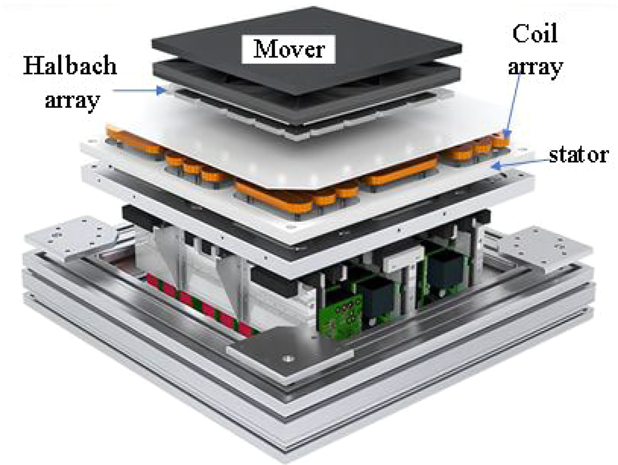
Structure diagram of a magnetic levitation planar motor. 82
Compared with other planar motors, magnetic levitation planar motors rely on physical and control principles such as direct drive (where power is delivered straight to the moving platform, minimizing transmission errors), magnetic levitation (which enables noncontact motion, resulting in zero friction) and multi-DOF closed-loop control (meaning the system continuously adjusts its position in multiple directions using feedback). These motors address common issues found in traditional mechanisms, such as limited movement range, high positional error and poor operational stability. Due to these features, magnetic levitation planar motors offer superior positioning accuracy, compatibility with different movement ranges (stroke compatibility) and adaptability to various environments. This makes them a promising option for current and future applications requiring high-precision micro-feed control, especially in fields that demand exceptional precision and stability, such as semiconductor lithography, delicate medical procedures and optical component adjustments.
Dynamic permanent-magnet synchronous planar motor
Xu 83 studied the dynamic magnet permanent-magnet synchronous planar motor (SPMPM), which uses a permanent-magnet array as the rotor and a coil array as the stator and directly converts electromagnetic energy into planar motion through electromagnetic interaction. Its positioning accuracy can reach micrometers or even nanometers. The advantages are that it can work in a vacuum environment, and the rotor has no wiring interference, does not require cooling devices and has high acceleration. The disadvantage is that the end effect of the moving permanent-magnet array makes accurate analysis and modeling difficult, and the coil utilization rate is low. This is suitable for fields such as lithography machines, precision manufacturing, aerospace, etc., that require high precision and dynamic performance. The structural diagram of the permanent-magnet synchronous planar motor is shown in Figure 66.

Structural diagram of a dynamic magnet permanent-magnet synchronous planar motor. 83
High-temperature superconducting planar motor
The high-temperature superconducting planar motor studied by Zhang Yiming 84 is a semi-composite structure with dynamic magnets. The rotor adopts a Halbach permanent-magnet array, and the stator adopts a high-temperature superconducting coil array. Its working principle is to generate electromagnetic force in the magnetic field of the permanent-magnet array by energizing the stator coil. The coil current is distributed through a current distribution algorithm and combined with attitude sensors for real-time monitoring and control, achieving six-DOF motion. This motor combines the characteristics of traditional magnetic levitation planar motors, such as high positioning accuracy, convenient extension of motion stroke, ability to work in high-vacuum environments and better load capacity. However, there are disadvantages such as high cost of high-temperature superconducting tapes, large processing errors in experimental platforms and the need to increase the frequency of current controllers. This is suitable for the semiconductor field, such as lithography machines, as well as industrial scenarios, such as pickups, detection systems and transportation systems. The structure of the magnetic levitation planar motor is shown in Figure 67.

Structure diagram of a high-temperature superconducting (HTS) planar motor. 84
Double-stator planar motor
Wang Yanlin 85 proposed a double-layer stator planar motor, which adopts a symmetrical configuration where the top and bottom coil arrays are relatively fixed, and the rotor operates between them. The top and bottom magnetic steel arrays, arranged in parallel, are adjacent to the corresponding coil layers and have the same arrangement direction. The double-coil array is designed with an angle between the coil arrangements. The key innovation is that the magnetic steel array is oriented towards adjacent coil layers on the strong-magnetic side. At the same time, the coil array is composed of a periodic arrangement of strip coils, with the pole spacing of the corresponding magnetic steel array precisely matched to that of the coil array. This design significantly improves the rotor's suspension stability and motion positioning accuracy by optimizing spatial electromagnetic coupling and magnetic circuit utilization while maintaining a simple structure. The structural diagram of a planar motor with a double-layer stator structure is shown in Figure 68.

Planar motor with a double-layer stator structure. 85 (1) Top coil array, (2) top coil fixing components, (3) bottom coil array, (4) bottom coil fixing components, (5) fixed connections and (6) sensors.
The institution has improved its force output capability and balance through a symmetrical dual-stator design, which, in itself, enhances reliability. The symmetrical distribution of electromagnetic force reduces the risk of unilateral heating and unbalanced magnetic pulling force, thereby reducing rotor vibration and tilt and improving long-term operational stability. However, its complexity also increases accordingly. Doubling the number of coils means that the number of drive circuits, wiring and thermal management points also increases accordingly. From a system perspective, there are more potential fault points. Therefore, its overall reliability depends not only on the lifespan of individual coils but also on the consistency of all components. Reliability design needs to ensure high symmetry of the dual stator in terms of electrical, magnetic and thermal characteristics and to consider introducing balancing algorithms in the control strategy to compensate for possible small performance deviations.
Rod-type linear motor
Bintang 86 invented a rod-type linear motor, in which the driving mechanism is nested with magnetic material in the housing to generate axial driving force. The clamping mechanism switches between releasing (bidirectional free movement of the moving part in the axial direction) and locking (position locking or unidirectional movement) states through an external magnetic field, synchronously constraining the action time and direction of the moving part. Its accuracy relies on the directional restriction of the DOFs of motion by clamping, achieving precise control of the axial motion direction and position. Due to its simple structure and flexible control, it is suitable for applications such as precision instruments, automation equipment and the aerospace industry that require strict motion constraints and lightweighting. However, the motor has inherent limitations: the mechanical switching of the clamping mechanism is prone to wear and aging due to high-frequency operation, external magnetic field dependence leads to electromagnetic interference sensitivity, and the demagnetization risk of the magnet material and the expansion constraints of thrust density also pose challenges to its application boundaries and long-term reliability. The principle of the rod-type linear motor is shown in Figure 69.

Structural diagram of a rod-type linear motor. 86
The unique reliability risk for this institution is concentrated in its mechanical–electromagnetic hybrid clamping mechanism. During high-frequency switching of the clamping mechanism, mechanical components are prone to aging from impacts and wear, leading to a decrease in clamping force or delayed response. The control method that relies on external magnetic fields is sensitive to electromagnetic interference, which may cause misoperation. In terms of long-term operational stability, permanent magnets are susceptible to demagnetization from repeated impacts and exposure to high temperatures, resulting in reduced driving and clamping forces. Its failure rate is expected to be higher than that of pure-electromagnetic or pure-mechanical drive mechanisms, as its failure modes combine both. The mechanism assembly must ensure micrometer-level fitting clearance for the mechanical motion pair, with a focus on controlling the coaxiality and axial movement of the clamping components and on accurately calibrating the timing synchronization between the electromagnetic drive and mechanical action after assembly to ensure rapid response and consistent clamping and release. The directions to improve its reliability include optimizing the material and wear-resistant design of the clamping mechanism, enhancing electromagnetic compatibility (EMC) protection and implementing online monitoring of the magnet status.
Micro-feed platform
Du and others 87 invented a micro-feed platform based on a micro-mechanical adjustable bistable mechanism, which balances the nonlinear electrostatic force generated by a non-staggered comb-tooth drive and the linear mechanical restoring force of the beam suspension structure, forming a stable state that can be controlled by a locking voltage. A micro-feed platform is a precision mechanical device used to achieve high-precision displacement control at the micrometer or even nanometer level. It is widely used in fields such as semiconductor manufacturing, optical processing and biomedical science that require extremely high precision. This institution has a simple structure, easy manufacturing, high stability and low energy consumption. The disadvantage is that, due to manufacturing process limitations, prototype equipment requires a high locking voltage, which may cause micromachining errors and asymmetry. The principle of the micro-feed structure is shown in Figure 70.
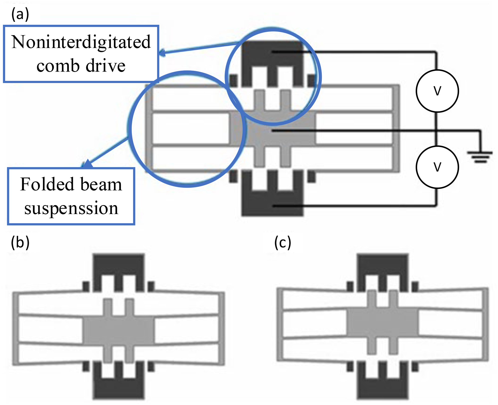
Schematic diagram of a micro-feed platform. 87
In terms of long-term operational stability, the suspended structure of the micro-feed platform may fatigue or creep under repeated electrostatic and mechanical stress cycles, leading to performance drift or failure. The failure rate is highly correlated with the uniformity and defect rate of the manufacturing process; for example, structural asymmetry caused by photolithography errors can introduce parasitic motion. Assembly must be carried out in an ultra-clean environment, with the core being the implementation of stress-free assembly principles, the use of controllable torque tools and the monitoring of structural deformation. At the same time, with microscopic vision, submicron-level precision is achieved in the alignment of electrostatically driven electrodes to eliminate parasitic motion. Reliability assessment typically requires high-acceleration life testing (HALT) to simulate long-term operation and track performance degradation.
Compared with other micro-feed mechanisms, this mechanism exhibits significant potential as a controllable bistable mechanism based on the principle of force balance. By balancing the nonlinear driving force and the linear restoring force, the system forms two discrete stable states. This mechanism transforms complex continuous control into robust state switching, fundamentally eliminating hysteresis, creep and static power consumption, providing inherent stability and energy efficiency beyond traditional piezoelectric or electrostatic actuators.
A cam mechanism for achieving linear intermittent feed
Ge 88 invented a cam mechanism for achieving precise linear intermittent feed. The core of this institution is a double-headed cylindrical cam body installed on the input shaft. One end is processed with an annular ridge for the stopping part, and the other end has three left spiral ridges for the driving part. One or more rollers are fixedly connected to a linear moving plate that requires linear reciprocating motion. When the mechanism is working, the input shaft drives the cam body to rotate continuously. When the roller engages the annular ridge of the stop part, the annular ridge's geometric shape prevents the cam's rotation from driving the roller to produce axial displacement, and the linear motion plate remains stationary. The contour of the spiral ridge forces the rotational motion of the cam to be converted into linear feed motion of the roller (and its connected motion plate). This process continues until the roller completes engagement with the spiral ridge, reenters and engages the annular ridge of the stop component, thus completing the “stop feed stop” intermittent motion cycle. The principle of the cam mechanism for achieving linear intermittent feed is shown in Figure 71.

A cam mechanism for achieving linear intermittent feed. 88 (1) Input shaft, (2) cylindrical cam body, (3) direct acting plate, (4) roller, (5) spiral ridge and (6) spiral ridge.
As a pure mechanical mechanism, its reliability evaluation is relatively traditional, but it requires extremely high standards. The core of long-term operational stability lies in the contact fatigue wear between the cam profile and the rollers. Under high-speed heavy loads, the point contact stress is enormous, which can easily lead to surface pitting and peeling, resulting in distorted motion trajectories and increased noise. The failure rate mainly depends on lubrication conditions, material selection and heat treatment. The reliability design of the institution includes using high-hardness, high-toughness bearing steel to manufacture the cam and roller; performing surface-strengthening treatments such as carburizing and nitriding; designing a forced lubrication system; and estimating its fatigue life through dynamic simulation.
Section 5 summary
The innovation of the new linear feed mechanism described in Section 5 has gone beyond local optimization of the traditional transmission chain, leading to a fundamental paradigm shift towards an integrated, intelligent motion system. Whether it is a planar motor for multi-DOF nanopositioning or a micromotion platform based on MEMS, its technical core is to integrate the driving, guiding and measuring functions and to reconstruct precision motion at the system architecture level.
However, the analysis in this section reveals that this high degree of integration has not only brought about a leap in performance but also led to an exponential increase in system complexity, posing reliability challenges not found in traditional institutions. Specifically, the multi-DOF planar motor faces the risk of motion instability due to its strong coupling characteristics. Under the long-term stress cycle, the flexible structure of MEMS micro platform has the inherent mechanism limitation of fatigue fracture. The reliability of the electromechanical hybrid clamping mechanism of a rod linear motor is subject to wear and aging in the process of high-frequency switching. However, the precise cam mechanism cannot get rid of the physical constraints of contact fatigue and pitting corrosion.
Together, these challenges indicate that the research frontier of the new mechanism has shifted from pursuing a breakthrough in a single performance index to solving the problem of coordinating design, control and reliability at the system level. The future development cannot be limited to gradual improvements in the mechanism ontology; it must rely on the interdisciplinary collaborative design paradigm. This includes using multi-physics field simulation based on digital twin to predict and avoid potential failure modes in the design stage. The adaptive control algorithm embedded with intelligent state monitoring is developed to realize the leap from “passive execution” to “active fault tolerance” and through new materials and new processes (such as wear-resistant coating and surface strengthening technology) to improve the life limit of key components from the physical level. The ultimate goal is to advance these cutting-edge institutions from laboratory prototypes to industrial-grade solutions that operate stably and reliably for a long time under extreme conditions and provide core power for the next generation of high-end equipment.
Summary
This review systematically sorts out four types of linear feed mechanisms (typical linear drive mechanisms, linear linkage mechanisms, high-precision linear feed mechanisms and new linear mechanisms) and constructs a multilevel technical spectrum based on key performance parameters such as accuracy, stiffness, load capacity and dynamic response, providing a clear qualitative framework for the selection and design of next-generation machine tools. The article not only clarifies the performance boundaries of various mechanisms, such as ball screws, which are suitable for micrometer-level precision and medium to high load scenarios, but also points out that piezoelectric drives and static-pressure guides can achieve nanometer-level resolution and have extremely high rigidity. It also points out that, under the dual goals of high speed and ultrahigh precision, a single mechanism often has limitations and must rely on a hybrid design to achieve complementary performance. For example, composite structures such as “linear motor + hydraulic hydrostatic support” or “dual drive ball screw + piezoelectric micro stage” can balance long stroke, high speed and nanoscale positioning. In the context of intelligent manufacturing and Industry 4.0, the integration capability of various linear feed mechanisms with sensors and data analysis systems has become a key indicator for evaluating their modernization adaptability. Some of the various institutions covered in this review have demonstrated good integration potential. For example, piezoelectric ceramic actuators, linear motors and magnetic levitation mechanisms, due to their inherent electrical control characteristics and high dynamic response capabilities, can be easily embedded with various sensors such as displacement, temperature and vibration and can be combined with IoT platforms and data analysis algorithms to achieve real-time state monitoring, fault diagnosis and predictive maintenance. However, traditional mechanisms such as ball screws and gear racks have difficulty integrating intelligent operation and maintenance functions without structural modifications and control upgrades. They often require additional sensor systems and the construction of digital-twin models to effectively achieve performance degradation warning and optimization control. Looking ahead, the research paradigm of linear feed technology is shifting from the pursuit of extreme breakthroughs in single performance parameters towards addressing system-level collaborative challenges under multi-physics field coupling. Future development primarily focuses on four directions. First, the intelligent upgrading of traditional mechanisms utilizes AI-driven dynamic compensation algorithms and digital-twin models to predict disturbances and adaptively adjust parameters. Second, the multi-physics collaborative design of high-precision mechanisms establishes a comprehensive evaluation system integrating dynamic stiffness, thermal stability and control bandwidth to advance systems from “precision actuators” to “intelligent motion units.” Third, the system-level reliability is enhanced through novel mechanisms that leverage digital twins and intelligent monitoring, transitioning from “passive execution” to “active fault tolerance.” Fourth, the integrated innovation of materials–structure–function explores rigid–flexible hybrid configurations and fusion with smart materials to fundamentally extend mechanism lifespan and performance boundaries. The classification framework and performance spectrum established in this study systematically define the technical characteristics and application boundaries of various mechanisms, providing a theoretical foundation and technical pathway for the development of linear feed mechanisms towards integrated intelligent perception, autonomous decision-making and precise control.
Footnotes
Author contributions
Jinglei Zhou: Book search, content analysis, writing—review and editing; Hanwen Yu: Topic selection, funding acquisition, writing—review and editing; Mingxuan He: Image search, graphic backup; Xuecheng Luan: Grammar review, review; Yandong Liu: Review, resources, verification; Zhang Ying: content analysis, writing—review and editing.
Funding
This research was funded by the Major Science and Technology Innovation Project of Shandong Province (No. 2025CXGC010201), the Natural Science Foundation of Shandong Province (No. ZR2024QE358) and Shandong Province Science and Technology based Small and Medium sized Enterprises Innovation Capability Enhancement Project (No. 2023TSGC0190 and No. 2024TSGC0342).
Declaration of conflicting interests
The authors declared no potential conflicts of interest with respect to the research, authorship and/or publication of this article.