
Abstract
To address the growing demand for temperature control precision and uniformity in wafer processing, a specialized electrostatic chuck temperature control system based on thermal control coatings is proposed, aiming to enhance thermal management robustness and homogeneity. This study employs a zoned control methodology using metal-oxide conductive coatings on silicon carbide wafer heating plates. A quadrant-based thermal control coating model was established, and finite element analysis was conducted to compare temperature distribution characteristics across three geometric configurations: sectorial, spiral, and zoned designs. The zoned structure was identified as the optimal configuration. The heating mechanism and heat transfer principles of the specialized chuck were analyzed, encompassing thermal conduction, convection, and radiation, with key factors influencing temperature distribution elucidated. Finite element simulation was utilized to optimize the thermal control system design, incorporating structured meshing to ensure computational accuracy. Experimental results demonstrate that precise regulation of coating current variations achieves maximum temperature difference control below 0.2°C and surface temperature uniformity stabilized at approximately 0.05°C, validating the efficacy of the methodology. These findings establish a robust theoretical foundation for further optimization of temperature control systems in semiconductor thermal management applications.
Keywords
Introduction
Special suction cups serve as critical components in high-end manufacturing fields such as semiconductor fabrication and precision optical processing. Their thermal control performance directly determines the machining accuracy and yield of precision devices such as wafers and optical lenses. Based on their operating principles, Special suction cups can be classified into electrostatic and vacuum types. The former employs electrostatic forces generated by DC voltage to adsorb wafers, commonly used in photolithography and etching processes; the latter utilizes negative pressure to hold workpieces and is widely applied in grinding and polishing of optical components. Both types demand strict thermal regulation, where the surface temperature deviation must be controlled within ±0.5 °C. Otherwise, thermal stress may cause pattern distortion on wafers or curvature deviations in optical lenses. In semiconductor processing, every 0.1 °C improvement in temperature uniformity of the heating plate can lead to a 3%–5% increase in product yield.1–3 Therefore, enhancing the thermal control performance of large-area chucks is a key pathway to improving process yields. However, conventional heating methods face significant limitations when applied to large-area chucks. Resistance wire-based heating structures often exhibit radial temperature deviations of 1.5–2 °C due to dispersed heat conduction paths. 4 Although induction heating offers rapid response, it suffers from eddy current edge concentration effects, resulting in temperature overshoots exceeding 1 °C at the chuck edges. 5 Recently, thermally controlled coatings have attracted attention for their ability to achieve seamless contact with chuck surfaces (<0.01 mm gap), short heat conduction paths, and fast thermal response, making them promising candidates for achieving high temperature uniformity. 6 In the design of large-area chucks, the structure of the coating is the core determinant of thermal uniformity, while multizone heating strategies have been widely validated as effective in reducing radial temperature gradients. 7
Current research on enhancing thermal control performance mainly focuses on three aspects: (1) In contact-based heating structure design, Hong et al. implemented a dual-zone heating plate using nichrome films and reduced temperature deviations to 1.2 °C, approximately 40% lower than conventional single-zone designs 8 ; (2) In induction heating optimization, Jin et al. proposed an electromagnetic–thermal coupled magnetic flux control method that reduced plate temperature deviation from 1.1 °C to 0.7 °C 9 ; Woo et al. further decreased the spacing between heating elements from 2 mm to 1 mm to reduce deviation by 0.2 °C, though at the cost of increased fabrication difficulty 10 ; Markevicius pointed out that structural gaps ≥0.5 mm may lead to a 15% reduction in heating rate and temperature fluctuations up to ±0.4 °C 11 ; (3) In coating materials and structural innovations, studies by Im et al. demonstrated that metal oxide-based conductive coatings improve heat transfer efficiency by approximately 20%, and can maintain temperature deviations within 0.6 °C under static conditions.12–14 Lee et al. developed a multizone thermal control coating structure that achieved a temperature uniformity of 0.087 °C in postexposure bake systems. 15
In recent years, multiphysics modeling has provided new perspectives for thermal control system design. Yoon et al. constructed a thermal–electrical–fluid coupled model to reveal the nonlinear relationship between backside gas pressure and temperature distribution in electrostatic chucks: increasing pressure below 5 kPa raised temperature deviation by 0.2 °C, while exceeding 10 kPa enhanced convective heat transfer and reduced deviation by 0.3 °C. 16 Lee and Jang showed that multizone heaters could reduce chuck temperature deviation by up to 42%,17–19 though the engineering tradeoff between the number of zones and control complexity remains unclear. Muneeshwaran noted that increasing the gap between the lid and hotplate from 0.5 to 1 mm expanded temperature deviation by 0.4 °C, but did not further analyze the coating's sensitivity to gap variation. 20 Moreover, existing studies on robustness under dynamic disturbances and control of manufacturing tolerances remain insufficient. While Yoon and Liu analyzed the influence of gas pressure and cooling flow rate on temperature uniformity, they did not establish a comprehensive multidisturbance robustness model.16,21 Although Wu and Zhang verified the coating structure's superiority in temperature consistency, the quantitative effects of fabrication deviations—such as ±0.05 mm linewidth error or 5% resistivity variation—on temperature distribution are still unclear, which may limit their applicability in mass production.13,22 Other studies provided further insights: Zhang et al. showed that radiative heating from the chamber wall can raise edge temperature by 0.3 °C22–24; Li et al. optimized the position of induction coils beneath graphite bases in metal-organic chemical vapor deposition reactors and reduced wafer temperature deviation by 37.5% 25 ; Liu et al. found that increasing coolant flow from 0.5 to 1.0 m/s reduced temperature deviation by 0.3 °C, though high flow rates may introduce vibration 21 ; Yoon further reported that coordinated control of high-voltage DC and gas pressure could decrease deviation by another 0.2 °C 26 ; Xu Longquan observed that increasing excitation current from 5 to 10 A improved heating efficiency by 50%, but reduced temperature uniformity by 20%, highlighting a tradeoff between electrical parameters and thermal uniformity. 27
In summary, although significant progress has been made in thermal structure design, material optimization, and multiphysics modeling, challenges remain in the areas of system robustness under multifactor disturbances, quantification of fabrication tolerances, and balancing performance with engineering feasibility. To address these challenges, this study proposes a novel four-zone annular coating structure combined with independently regulated current control. A coupled electrothermal finite element model was developed to analyze the influence of geometrical design, electrical input, material properties, and environmental disturbances on thermal uniformity. The proposed solution aims to balance high thermal precision, structural simplicity, and robustness under practical operating conditions, providing a feasible pathway for scalable implementation in wafer processing and other high-end manufacturing applications.
Heating structure and transfer mechanism of special suction cups
Heating structures of special suction cups
Two primary heating methodologies are employed in electrostatic suction cups: thermal conduction and radiation. 28 The thermal conduction mechanism employs resistance wires or sheets as heating elements in electrostatic suction cups. When current flows through these conductors, electrical resistance generates heat through the Joule heating effect. This method ensures uniform temperature distribution and precise thermal control; however, it is characterized by slow heating rates and low energy efficiency. The radiation-based heating principle employs inductive coils to indirectly heat the electrostatic suction cup. When an alternating current flows through the coil, it generates an alternating magnetic field, which induces an electromotive force in the conductor through electromagnetic induction. This phenomenon, governed by Faraday's Law of Induction, produces strong eddy currents. While this method enables rapid heating and high energy efficiency, it suffers from nonuniform temperature distribution and poor thermal control due to the inherent limitations of electromagnetic field penetration depth.
Spiral-configured resistance/inductive heating structures enable temperature control in electrostatic suction cups. However, their geometric constraints introduce significant interfacial gaps, severely degrading thermal uniformity. 11 Furthermore, incomplete contact with the suction cup surface reduces heating efficiency and rate by limiting effective energy transfer. The application of a conductive temperature-controlled coating as the core heating element resolves these challenges. 12 The fully conformal coating, adhering seamlessly to the electrostatic suction cup surface, demonstrates superior heat transfer efficiency and exceptional thermal uniformity (Figure 1). This configuration eliminates geometric mismatches while maintaining rapid heating rates and precise temperature control.
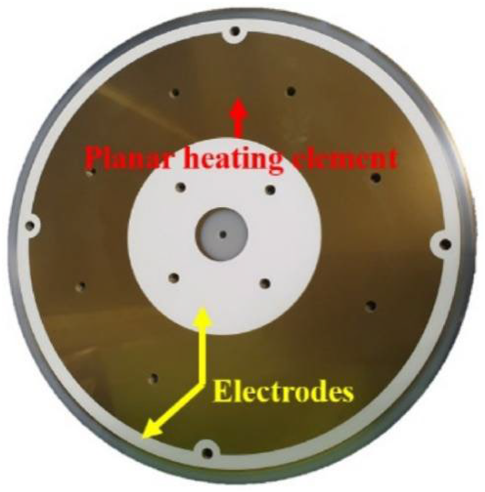
Specialized suction cups based on temperature-controlled coatings. 12
The heating structure serves as the physical foundation for achieving thermal uniformity control in electrostatic suction cups. To address the challenge of nonuniform temperature distribution across large-area substrates, a structural control methodology is implemented by segmenting the heating element into multiple zones. Through precise adjustment of geometric parameters (e.g. width, spacing, and layer thickness), the electrical resistance distribution across zones is optimized, thereby enhancing temperature homogeneity. This zonal design strategy is critical for maintaining thermal stability during high-precision semiconductor manufacturing processes. Therefore, the design of the heating structure plays a critical role in achieving thermal uniformity control of electrostatic suction cups.
Mechanisms of heat transfer
In the special suction cup based on temperature-controlled coating, the temperature-controlled coating with high thermal conductivity is used as the heating medium, and the circuit structure of the temperature-controlled coating is designed to make its resistance distribution more uniform, so as to ensure the temperature distribution uniformity of the temperature-controlled coating from the physical structure. In electrostatic suction cups based on temperature-controlled coatings, three heat transfer mechanisms coexist: thermal conduction, convective heat transfer, and radiative heat transfer (Figure 2). The substrate is attached to the suction cup surface through complete adhesion. Thermal conduction refers to heat transfer via direct contact between objects, moving from higher-temperature regions to lower-temperature regions, primarily occurring between the temperature-controlled coating and the upper/lower surfaces of the suction cup. Convective heat transfer involves heat movement through a flowing medium, mainly happening at the interface between the substrate's upper surface and ambient air. Radiative heat transfer describes energy transmission as electromagnetic waves, predominantly occurring between the temperature-controlled coating and the surrounding environment. Convective heat transfer refers to energy transfer via fluid motion between spatially separated regions, primarily occurring at the interface between the substrate's upper surface and ambient air; radiative heat transfer describes electromagnetic wave-mediated energy exchange, predominantly occurring between the temperature-controlled coating and the surrounding environment.

Schematic diagram of heat transfer of temperature-controlled suction cups.
Heat conduction is a mechanism of heat transfer resulting from the mutual collisions and interactions of microscopic particles, termed thermal conduction.
29
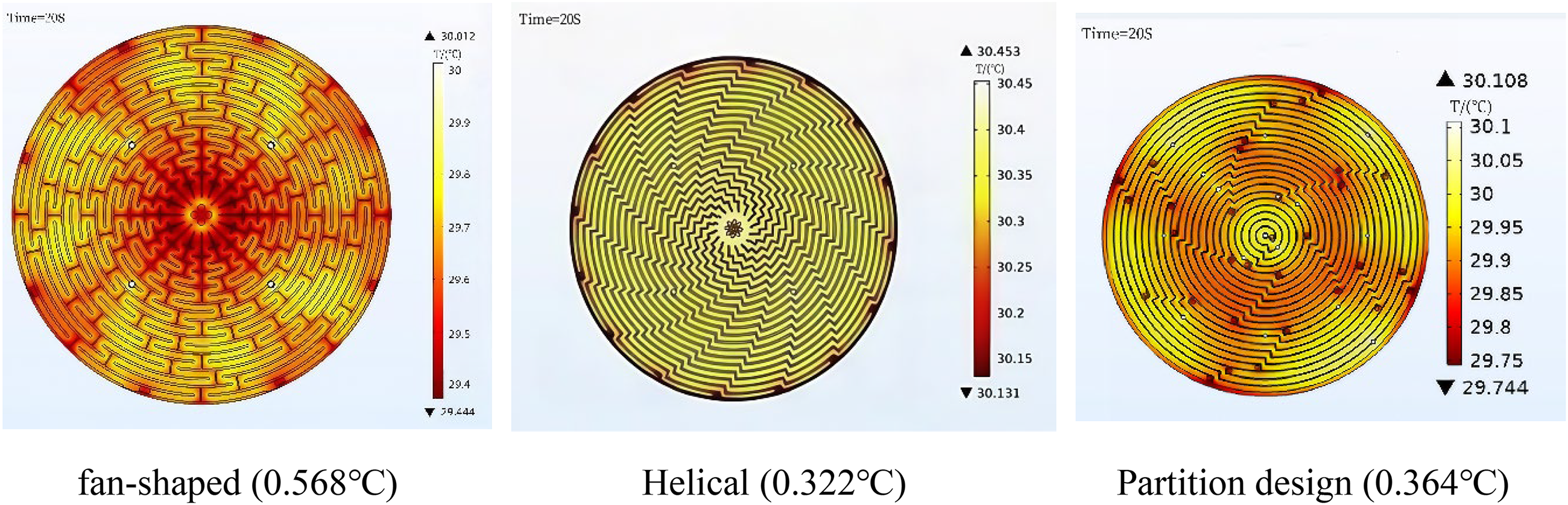
According to Fourier's law, the rate of heat transfer from a high-temperature surface to a low-temperature surface is as shown in equation (1):
This relationship is formally defined as Fourier's Law.
Thermal convection refers to the different temperatures of the fluid due to the relative movement of heat transfer caused by the way, can be expressed by the Newton cooling formula convection heat transfer as equation (2) shown in the formula:

Thermal radiation is a type of heat transfer that radiates energy into the surrounding space through electromagnetic waves. According to Stephen Boltzmann's law, the amount of radiation from an actual object is shown in equation (3):

Model establishment
Establishment of simulation models and conditions of boundaries
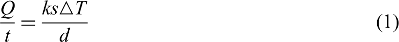
Typical wafer heating discs use spiral metal wires or metal films to form resistive heating elements; however, this method is constrained by shape and volume limitations, impacting the thermal uniformity of the wafer heating discs. The structural model of the temperature-controlled chuck must satisfy the comprehensive requirements for thermal uniformity, thermal response speed, and system reliability during semiconductor wafer heating processes. Material selection for each structural layer is based on thermal performance, mechanical strength, and functional compatibility. Specifically: Heating layer: Metal-oxide conductive coatings with stable resistivity and excellent manufacturability enable efficient low-voltage heating. Electrode material: Silver provides superior conductivity to minimize terminal energy loss and facilitate soldering connections. Load-bearing layer: Silicon carbide (SiC) exhibits exceptional hardness, superior thermal conductivity, high-temperature stability, and strong oxidation resistance under sustained heating conditions, with reduced conduction and switching losses. 30 Insulation layer: Polyvinyl alcohol (PVA) and SiO₂ ensure electrical isolation between conductive layers and electrodes while buffering thermal stress induced by temperature gradients. The overall structural design adheres to multiphysics coupling optimization principles, balancing thermal control performance with practical manufacturability. To address these challenges, metal-oxide conductive coatings and silver electrodes were deposited via physical vapor deposition (PVD) equipment. As illustrated in Figure 3, these components serve as Joule heating media to electrically heat the silicon carbide layer of the heating plate. The electrothermal activation system, illustrated in Figure 3, integrates a metal oxide conductive coating with a silver electrode as the thermal interface material, enabling controlled electrical heating of the silicon carbide layer within the heating disc.
Model structure of special suction cups based on temperature-controlled coating.
The metal oxide conductive coating and silver electrode serve as the thermal interface material for electrothermal activation of the silicon carbide layer in the electrostatic wafer chuck. The specific heating method is to employ high-precision pulse width modulation (PWM) control signals to modulate the on–off ratio and frequency of the power supply, where varying duty cycles directly determine the heating power output, enabling precise temperature regulation of the heating element. According to Joule heating law, the heat generated by electrothermal activation is expressed as:
The primary component of the specialized suction cup is silicon carbide (SiC), which exhibits exceptional hardness, superior thermal conductivity, and remarkable oxidation resistance under continuous high-temperature exposure, with minimal conduction and switching losses. 30 Silver (Ag) is utilized for terminal contacts due to its excellent electrical conductivity, while silicate coatings are applied to ensure chemical stability during sustained heating processes.
In semiconductor thermally controlled suction cups, the thermally conductive coating serves as the fundamental mechanism for achieving temperature uniformity.
To enhance the radial temperature gradient consistency from the center to the periphery, the coating is configured with a four-annular partition structure (as shown in Figure 4), incorporating radially uniform return circuit pathways. Silver electrode contacts connected to the heating power supply are positioned at the terminations of each circuit.

Temperature control coating circuit structure.
The temperature variation of the conductive coating is induced by electrical energy input, governed by the material's specific heat capacity. The coating's thermal mass can be quantified based on conductive heating principles, while its electrical resistance and geometric constraints (e.g. minimum conductor width derived from the required thermal length) enable power requirement calculation. Subsequent iterative optimization refines the design parameters to achieve the target temperature uniformity.
The basic parameters required are as follows:
Specific heat capacity of the coating:
Demand temperature: 5°C
Resistivity:
Cross-sectional area:
Coating resistance: In the case of a line width of 5 mm, the resistance value is about 25 ohms per cm.
Length:
Resistance of the area where each terminal is located: a total of 16 bars, each bar resistance of about 2250 Ω
Density of the coating
Plating quality:
Meet the heat required to raise 5°C in 2020 seconds:
Power:
Due to the fact that each resistor has a resistance of approximately 2250 ohms, the voltage is calculated to range between 170 and 180 V (per Ohm's Law).
The thermal conductivity of the silicon carbide (SiC) substrate is set at 120 W/(m·K), 30 suitable for high-temperature semiconductor processing scenarios. Its 9.2 mm thickness balances structural strength and heat transfer efficiency, meeting the ≥9 mm strength standard for 300 mm wafer chucks documented in. 25 Simulation verifies that this thickness achieves a 1.2% faster response than 9 mm designs while incurring only 0.8% slower response versus 9.5 mm configurations, representing the optimal equilibrium.The thermal conductivity of the silicon carbide (SiC) substrate is set to 120 W/(m·K), 30 which is suitable for high-temperature semiconductor processing scenarios. Its thickness of 9.2 mm meets both structural strength and heat transfer efficiency requirements, conforming to the strength standard of ≥9 mm for 300 mm wafer chucks specified in Reference. 25 Simulation verification shows that compared with a thickness of 9 mm, the response speed is increased by 1.2%, and compared with 9.5 mm, it is only reduced by 0.8%, making it the optimal balance value. The 0.1 mm thickness of the metal oxide coating has been verified by the PVD process: within the sputtering power range of 100–300 W, the coating density corresponding to this thickness is >95%, the resistivity CV value is <3%, and it is consistent with the optimal thickness reported by Im et al., 12 which can ensure the stability of heating efficiency. The 0.1 mm thickness of the silver electrode complies with semiconductor industry specifications, which not only ensures the uniformity of current conduction but also enables mass production, with an edge precision of <0.02 mm. The 0.1 mm thickness of the PVA insulating layer refers to electronic device standards and has been verified by experiments. At this thickness, the insulation resistance is >10¹⁰ Ω (withstand voltage 500 V), the thickness deviation is <5%, and the uniformity is optimal, which can effectively avoid the impact of electric leakage on temperature control accuracy.Based on the target of heating from 25°C to 30°C within 20 s, the required power is determined to be 238.2 W through thermodynamic calculations. To compensate for the difference in edge heat dissipation, a zoned power supply design is adopted, with 130 V applied to the inner zones (Zones 1 and 2) and 150 V applied to the outer zones (Zones 3 and 4). Table 1 lists the main simulation parameters. Table 1 consolidates the critical simulation parameters derived from the thermal–electrical coupling model.
Main simulation parameters.

Boundary conditions and convergence criteria
To ensure reliability and precision of finite element simulations, computational accuracy was guaranteed through the following configurations:
Boundary conditions Thermal boundaries: Convection coefficient between chuck exterior and environment: 5 W/(m²·K) (referencing semiconductor cleanroom measurements
21
). For disturbance analysis: 30–50 W/(m²·K). Ambient temperature: 25°C. Base contact surface with pedestal: Adiabatic boundary (heat loss <1%).Coating-substrate interface: Ideal thermal contact (thermal resistance = 0).Thermal radiation effects were neglected due to small system temperature differences (<10°C). Electrical boundaries: DC voltage applied to silver electrodes: 150 V (outer zones)/135 V (inner zones). Coating edges: Electrically insulated to prevent current leakage. Initial conditions: Simulation start temperature: 25°C (matching experimental environment). Zero initial stress/displacement. Convergence criteria
Energy-based convergence criterion with residual threshold <1 × 10⁻⁶. Grid independence verification: Maximum temperature variation <0.01°C when elements increased from 80 to 120 k. Variation <0.005°C at 150 k elements.120 k-element model adopted to balance accuracy and computational efficiency.
Division of the grid
To ensure both the accuracy of thermal field simulations and computational stability, this study employed triangular elements with an ultrarefined meshing strategy, combined with gradient-based mesh control tailored to the characteristics of the thermal gradient distribution. Specifically, in the interface region between the thermal control coating and the substrate—where heat flux variations are most significant—a minimum element size of 0.48 mm was applied to accurately capture local microscale temperature gradients. In contrast, the main body of the substrate adopted a graded mesh structure with a maximum element size of 11.2 mm and an element growth rate of 1.35, balancing computational efficiency with precision.
Furthermore, to maintain overall mesh quality and prevent numerical instability, dual geometric quality criteria were strictly enforced: the element skewness was limited to below 5%, and the Jacobian determinant was maintained above 0.8. These measures effectively suppressed potential distortions in the simulated thermal field caused by mesh deformation. Detailed meshing parameters are provided in Table 2.
Main setting parameters.

The temperature-controlled coating network segmentation model is obtained as shown in Figure 5.

Mesh division mode.
Simulation of temperature control coatings
Fundamentals of simulation and analysis of results
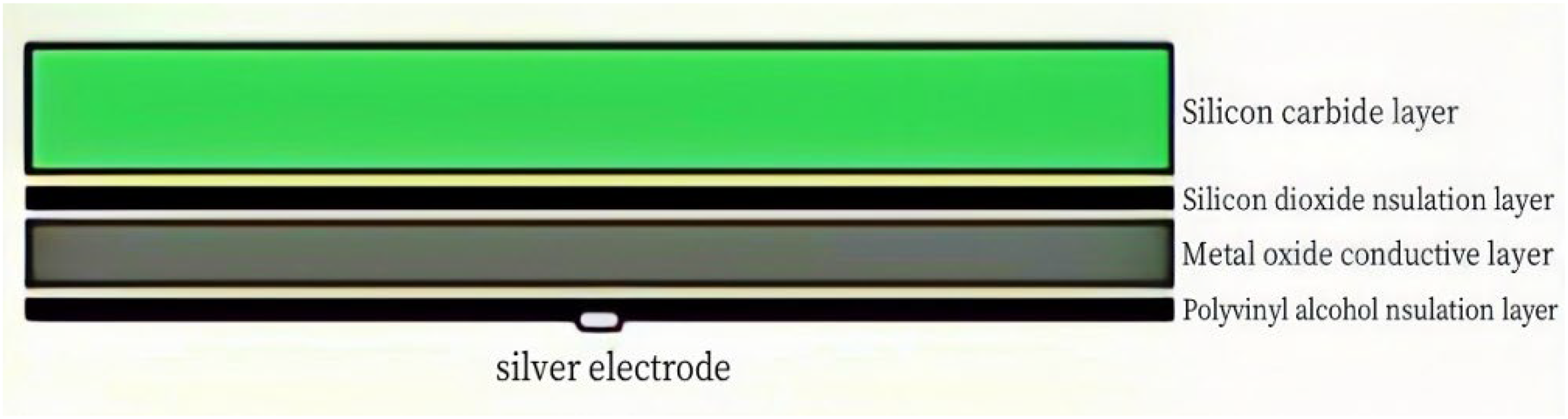
Graphic design optimization: Through implementing fan-shaped octagonal configurations, helical geometries, and partitioned domains optimized for simulation purposes, the simulation outcomes are presented in Figure 6.
The eight-partition uniformly distributed fan-shaped configurations exhibit degraded thermal boundary performance at partition edges. The spiral configuration demonstrates minimal thermal gradient variation across the domain. However, conventional manufacturing processes fail to achieve the required pattern fidelity, necessitating design optimization. Comprehensive consideration of thermal radiation and diffusion effects, coupled with simulation results from zoned design structures, confirms enhanced temperature uniformity.
Based on the adoption of the partitioned design for the temperature-controlled coating structure, this study further analyzes several key parameters closely related to thermal performance, including line width, voltage, electrical resistivity, environmental convective heat transfer coefficient, and the contact resistance of the backside connector. Specifically, the linewidth directly affects the distribution of current density: an overly narrow linewidth may cause localized overheating due to current concentration, while an overly wide linewidth reduces the flexibility of localized temperature control. The voltage, as the primary driver of heating power (P = U²/R), has a direct influence on regional heat output; its fluctuation can significantly impact the system's steady-state temperature error. The electrical resistivity, as an intrinsic property of the conductive coating, determines the unit resistance per length. Its temperature dependence may further induce electrothermal coupling effects, compromising the robustness of thermal control. The environmental convective coefficient reflects the system's heat dissipation capacity under actual operating conditions, which is critical for ensuring thermal stability. Meanwhile, the contact resistance at the backside connector plays a vital role in localized heat loss; poor electrical contact can lead to thermal hotspots and uneven temperature distribution. Notably, significant interactions exist among these parameters. For instance, linewidth and voltage form an electrostructural coupling: specific combinations can be tuned to balance power density, temperature uniformity, and control sensitivity. Similarly, resistivity and convection exhibit material–environment coupling: structures with high resistivity require stronger convective cooling to avoid overheating, whereas low-resistivity designs are less sensitive to environmental variation. Additionally, contact resistance tends to decrease nonlinearly with increasing linewidth; however, excessively wide linewidths may compromise the independence of heating zones, implying the need to determine a critical linewidth that balances electrical performance and zoning effectiveness.
The simulation results confirm these relationships by comparing temperature distributions under different parameter values and combinations, clearly demonstrating the impact of each factor on thermal uniformity. These findings provide theoretical support and design references for further optimization of thermal control structures.
Impact of line width variation: Considering manufacturing tolerances (±0.05 mm), the simulation evaluates line width deviations’ impact on thermal performance, demonstrating that ±0.05 mm variations meet the thermal uniformity requirement of ±0.5°C. Figure 7 presents the simulation results confirming compliance with design specifications.
Voltage effects: Augmented connectors and PEEK insulation rings necessitate voltage optimization. Preliminary simulations indicate that a dual-layer configuration (150 V for outer zones, 5 V for inner zones) achieves minimal temperature gradients while maintaining thermal uniformity within ±0.5°C. Although high-frequency pulsed voltages reduce energy input, they compromise temperature consistency and are therefore excluded. Simulation results validating this design are presented in Figure 8.
Effect of resistivity: Increased resistivity elevates the 20-s thermal gradient (ΔT₂₀s), though axial temperature consistency (ΔT_axial ≤1°C) is maintained. Simulations reveal minimal ΔT variation (<0.5°C) under constant voltage with variable resistivity, demonstrating better robustness. Compared to uniform resistivity distribution, nonuniform configurations exhibit marginal ΔT increases (e.g. 48 V/5 × 10−5 Ω·m → ΔT₂₀s = 5°C; 48 V/7 × 10−5 Ω·m → ΔT₂₀s = 3.8°C). Voltage adjustment becomes necessary to satisfy the thermal uniformity criterion (ΔT_max ≤2°C), as validated in Figure 9.
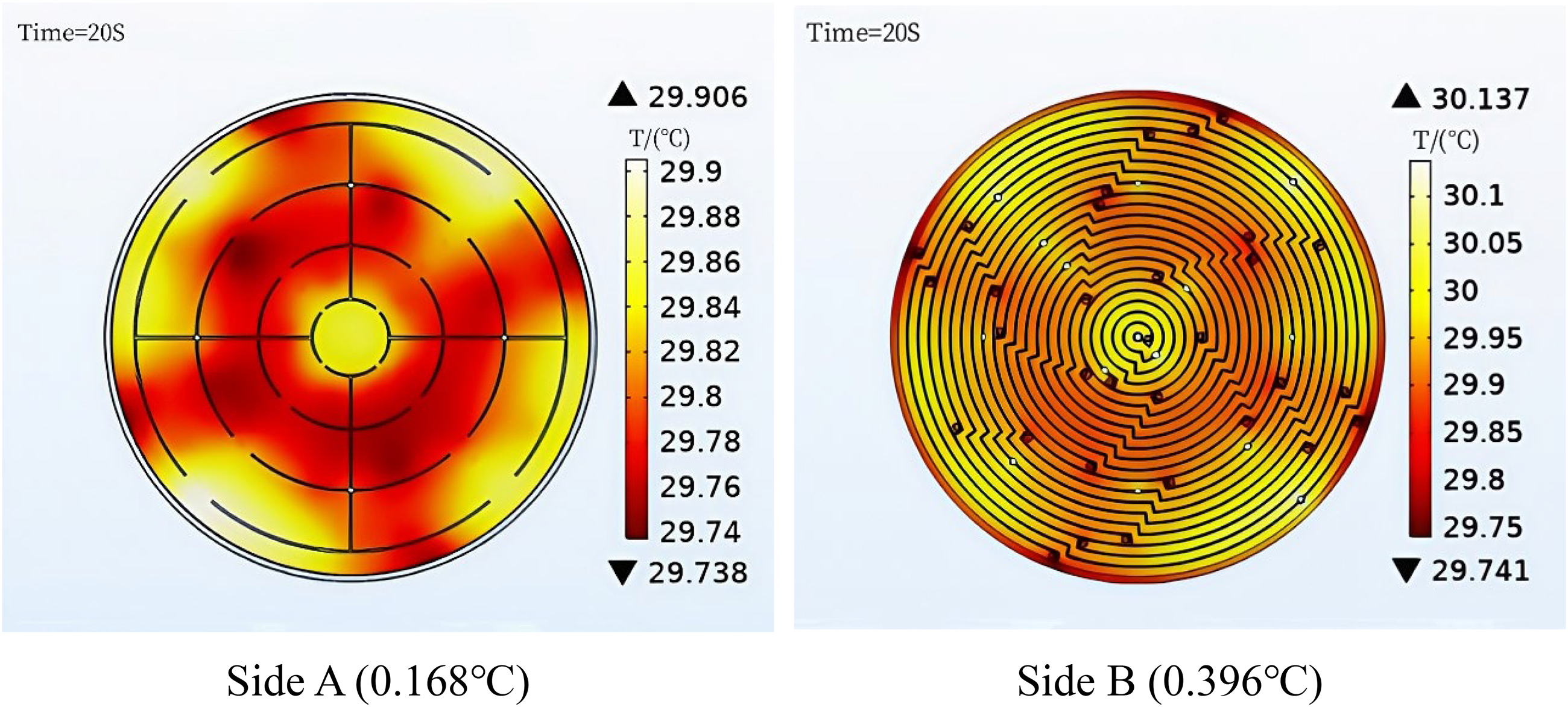
Thermal perturbation analysis: Under applied critical voltages (outer zones: 150 V, inner zones: 135 V), heating via silver terminals introduces environmental disturbances. The front-side temperature difference reaches ΔT_front = 0.168 °C at 30 °C, while the rear-side ΔT_rear = 0.396 °C, both satisfying thermal gradient requirements. The design demonstrates inherent stability against thermal perturbations with optimized voltage distribution. Figure 10 validates the simulation outcomes.
Aerodynamic perturbation: The voltage configuration of 150, 150, 135, and 135 V for the thermal control coating's four heating zones was designed to address structural, resistive, thermal disparities, and power balancing requirements where outer zones (lower resistance, stronger heat dissipation) require higher voltage for thermal loss compensation, while inner zones (higher resistance, thermal accumulation) necessitate lower voltage to prevent overheating. This asymmetric strategy achieves dynamic power balance, enhancing temperature uniformity. Under room-temperature validation using silver terminals with airflow perturbation (convection coefficient increased from 5.0 to(30, 40, 50)W/(m²·K)), results demonstrated: Face A maximum temperature difference of 0.168°C at 30°C and Face B difference of 0.4°C—both within ±0.5°C uniformity requirements (SEMI S10). The design exhibited minimal sensitivity to airflow disturbances (<0.05°C fluctuation), confirming robust stability, with simulation results detailed in Figure 11.
Environmental factors: after superposition of pneumatic and temperature, only room temperature is considered, and heating is carried out through the silver terminals, the heating film layer can reach 5 °C temperature control requirements within 20 s, and when there is airflow disturbance to increase the heat transfer coefficient during the heating process, the temperature consistency of the A-side and the B-side basically meets the requirements of the accuracy, simulation results in Figure 12.
The effect of backside connectors: increased connectors, peek insulation, still have a good temperature consistency, simulation results in Figure 13.
Simulated thermal distribution of heating plate with different coating design structures.

Simulated thermal distribution of heating plate under varying line widths.

Simulated thermal distribution of heating plate under varying applied voltages.

Simulated thermal distribution of heating plate with varying resistivity.
Simulated thermal distribution of heating plate under thermal perturbation.

Simulated thermal distribution of heating plate under airflow disturbance.

Simulated thermal distribution of heating plate under thermal environmental factors.

Simulated thermal distribution of heating plate with added backside connectors.
In this section, the temperature variation of the temperature-controlled coating after heating is simulated via COMSOL software by considering structural, processing, and environmental factors including thermal perturbations, aerodynamic disturbances, surface resistivity variation, and distribution. The analysis demonstrates enhanced robustness, mitigating partition interface thermal gradients and simplifying manufacturing complexity for optimized embedded regions.
Since the system operates in an ambient temperature environment, the simulation's initial temperature is set to 25°C, the target temperature is 30°C, and the simulation voltage is set to 80 V DC constant voltage. Figure 14 presents the thermal distribution contour map of the temperature control coating upon achieving the target average temperature.

Heat distribution of heating disc simulation.
From the simulation results, it can be seen that the maximum and minimum temperature difference in the temperature-controlled coating is 0.394 °C. Although the radial temperature distribution from the center to the edge exhibits a measurable gradient, it has met the initial requirement for high-precision temperature control. In the actual temperature control process, independent temperature control is implemented for different regions to reduce the radial temperature gradient from the center to the edge and enhance temperature uniformity across regions. In the actual temperature control process, independent temperature control is implemented for different regions to reduce the radial temperature gradient from the center to the edge and enhance temperature uniformity across regions. The suction cup surface temperature must align with process parameters defined by operational instructions. To achieve this, prompt heating power application is required during initial startup to reach the target temperature swiftly. However, prolonged natural cooling cycles in specialized suction cups necessitate continuous power modulation. Therefore, precise thermal equilibrium must be maintained through integration with a PID control algorithm, ensuring high-precision and uniform temperature control.
Experimental validation
Experiment
Figure 15 illustrates the schematic diagram of the system, which comprises a control cabinet, specialized suction cups, cooling devices, temperature sensors, and other essential components. To enhance simulation accuracy and achieve clear temperature control, this article proposes the following assumptions derived from system operational characteristics and physical properties. These assumptions aim to accurately model critical phenomena while maintaining computational efficiency.
Considering that noncritical structural components exert minimal impact on the surface temperature of specialized suction cups, nonessential components are excluded from simulation modeling. This approach reduces computational overhead while enhancing the dynamic response and computational speed of the suction cup model. The stable and sealed environment surrounding the special suction cups, featuring negligible air convection and a temperature-controlled coating applied to the heating surface for achieving high thermal efficiency, ensures that the effects of air thermal convection and thermal radiation from the surroundings remain negligible in simulations.

Experimental schematic diagram.
Figure 16 illustrates the experimental setup equipment. The equipment is equipped with a specialized suction cup, temperature sensors, and a dedicated cooling system. The specialized suction cup serves as the primary research subject. Fifteen temperature sensors are radially and uniformly distributed on its surface to monitor temperature variations in real time. After each experiment, forced-air convection cooling achieved uniform thermal equilibration of the entire plate to ambient temperature within 10 min, significantly reducing experimental downtime. The integration of temperature sensors and the cooling system ensures environmental constancy and operational safety, thereby guaranteeing the precision and reliability of experimental results.

Equipment diagram at the experimental site.
Experimental results
In order to further verify the temperature control stability of the system, 10 consecutive temperature control tests were carried out in the ambient temperature environment, starting from the ambient temperature of 25°C, and each time the temperature was increased by 0.5°C, and the test data obtained were shown in Table 3, from which it can be seen that the average temperature steady-state error in the 10 temperature control tests was maintained at about 0.05°C, and the maximal temperature difference between all the temperature measurement points in the whole temperature increase process has been less than 0.2°C, and the adjustment time has been less than 20 s. The whole temperature control system has good stability. less than 20 s, the whole temperature control system has good stability.
Ten consecutive temperature control test data.

Figure 17 graphically presents the statistical dispersion characteristics of experimental data, demonstrating the mean values and error distributions of key thermal control metrics.

Mean values with error bars for thermal control metrics.
Blue bars (“Steady State Error”) represent the average steady-state temperature deviation, with a mean value of 0.038°C and error bars of ±0.010°C, demonstrating the precision of steady-state temperature control.
Red bars (“Max Temperature Difference”) indicate the mean maximum temperature differential of 0.117°C with error bars of ±0.027°C, reflecting the dispersion of temperature distribution across the chuck surface in repeated tests.
The observed experimental data dispersion can be attributed to three primary physical mechanisms. First, the intrinsic accuracy limitations of temperature sensors (±0.01 °C) introduce a baseline measurement bias. Second, airflow fluctuations within the workshop environment lead to slight variations in the surface convective heat transfer coefficient, thereby inducing localized oscillations in temperature distribution. Third, temperature-dependent drift in coating resistivity, coupled with voltage ripple in the power supply, results in subtle fluctuations in thermal output. Collectively, these factors define the expected range of experimental variability. The fluctuation intervals indicated by the error bars are consistent with quantitative estimations based on these physical mechanisms, confirming that the data dispersion is predominantly driven by real physical perturbations rather than random errors introduced by the test system.
This study centers on the synergistic effect of a four-zone annular structural design and current-based control strategy, establishing an electrothermal coupled model to analyze the resulting temperature field distribution. The key evaluation metrics include steady-state temperature control accuracy and interregional thermal uniformity. Lee et al. 15 achieved a temperature control accuracy of 0.087 °C by integrating a multizone resistive coating with an active cooling system, confirming the effectiveness of zoned thermal regulation. Building upon this foundation, the present study adopts a four-zone annular layout, wherein each zone is implemented as a continuous spiral-shaped conductive coating. Compared with the two-zone sector design proposed by Wang et al., 18 the adopted structure more effectively accommodates the radial thermal gradient. Additionally, unlike the grid-type partitioning used by Zhang et al., 20 the annular configuration is better suited to the geometry of circular heating plates, thereby mitigating corner-induced temperature nonuniformity. From the perspectives of control strategy and precision, this study integrates independent current control for each zone, enabling direct modulation of localized Joule heating and faster response times. As a result, a control accuracy of 0.05 °C was achieved—an improvement of approximately 43% over the benchmark set by Lee et al. 15 Furthermore, compared to the voltage control method of Li et al. 23 and the single-zone global control approach of Chen et al., 21 current-based regulation offers higher precision and, when implemented with zone independence, better accommodates differential heat dissipation, thereby enhancing overall thermal uniformity.This “structural optimization + direct current control” strategy achieves a breakthrough in temperature precision while simplifying the cooling system, offering a valuable solution for high-precision thermal management of large-area heating plates.
Conclusion
To improve the temperature uniformity of Special suction cups from a structural perspective, this study first analyzed the key factors affecting the thermal consistency of the heating plate. The conductive coating of a large-area wafer heating plate was divided into four concentric zones with uniformly distributed resistance. Based on this, the structure of the specialized chuck was appropriately simplified with reasonable assumptions. A finite element model of the thermal control coating was then established using COMSOL Multiphysics, focusing on a comparative analysis of three geometrical configurations: sector-type, spiral-type, and partition design. Simulation results demonstrated that the zoned design outperformed the other configurations in terms of thermal uniformity. Upon determining the optimal coating structure, further control of current distribution across the zones enabled surface temperature consistency to be stabilized within 0.05 °C, effectively reducing interzone error coupling and significantly enhancing thermal uniformity. These results strongly validate the effectiveness and feasibility of the proposed design.
In this study, technological innovation has been achieved in the design of temperature-controlled coating structure and optimization of thermal response. A four-zone annular temperature-controlled coating structure is proposed. Compared with the traditional single-zone or two-zone heating method, this structure improves the temperature uniformity by independently regulating the heating power of different zones, effectively solving the large-size wafer heating technology in terms of temperature distribution uniformity. The metal oxide conductive coating is used to replace the traditional resistance wire, nickel–chromium film and other heating methods to improve the thermal response time of the temperature control coating. At the same time, multiphysical field coupling simulation is used to comprehensively consider the effects of current field, heat conduction field, and air convection field on the temperature control system, optimize the coating design, and improve the design accuracy and system robustness of the temperature control technology.
The traditional temperature control method mainly relies on single-area heating, there are uneven temperature distribution, slow response speed and low temperature control accuracy, etc. Special suction cups for semiconductor manufacturing, optical processing, aerospace, new energy batteries and other high-end manufacturing areas provide a new temperature control solutions, greatly improving the stability of the production process and the consistency of the product, and help to enhance the overall technical level and competitiveness of enterprises in the field of intelligent manufacturing and high-end equipment manufacturing. Manufacturing in the field of intelligent manufacturing and high-end equipment to improve the overall technical level and competitiveness of enterprises.
Footnotes
Acknowledgments
The authors would like to express appreciation to the anonymous referees and the editor for their helpful comments.
Ethical considerations
Not applicable. This article does not contain any studies with human or animal participants.
Consent to participate
Not applicable. This article does not contain any studies with human or animal participants.
Consent for publication
Not applicable. This article does not contain any studies with human or animal participants.
Authors’ contribution
Diqing Fan: conceptualization, literature review, methodology, 3D modeling, simulink simulations, data analysis, data interpretation, and writing original draft; Jianyu Liu: conceptualization, visualization, writing original draft, writing review and editing, data curation, methodology, investigation, formal analysis, and validation; Shuo Zhang: writing original draft, writing review editing, visualization, methodology, investigation, and formal analysis; and Xintian Liu in conceptualization, methodology, supervision, and writing—review and editing.
Funding
The authors disclosed receipt of the following financial support for the research, authorship, and/or publication of this article: This work was supported by the project of Shanghai Science & Technology Commission (Grant No. YDZX20213100003013).
Declaration of conflicting interests
The authors declared no potential conflicts of interest with respect to the research, authorship, and/or publication of this article.
Data availability statement
All data in the manuscript is available through the responsible corresponding author.
Trial registration number/date
Not applicable. This article does not contain any studies with human or animal participants.