
Abstract
Photovoltaic (PV) systems experience significant power losses under partial shading conditions (PSCs) due to mismatched module outputs, limiting maximum power extraction. To address this issue, a hybrid maximum power point tracking (MPPT) algorithm, artificial neural network–Grey wolf optimization (ANN–GWO), is introduced, combining ANNs and GWOs. ANN reduces tracking time to approximately 0.02 seconds during rapid weather fluctuations, while GWO enhances power extraction under severe shading conditions. On the grid side, model predictive control (MPC) optimizes single-phase inverter operation, ensuring stable grid integration and efficient power transfer for residential and microgrid-based electric vehicle (EV) charging. This approach improves dynamic tracking efficiency by over 9% and reduces MPPT tracking time by up to 99.98% compared to conventional methods. Additionally, MPC lowers total harmonic distortion (THD) from 2.56% to 1.56%, enhancing power quality and response time. Implemented on the Texas Instruments TMS320F28379D DSP, the system ensures fast and stable power tracking, outperforming traditional control methods. Both simulations and real-world experiments validate the proposed system, demonstrating significant advancements in PV-based EV charging performance. This study focuses on developing a Hybrid ANN–GWO MPPT combined with MPC-based inverter control to enhance PV-powered EV charging under PSC, aiming to improve tracking efficiency, reduce THD, and implement a real-time DSP-based experimental setup.
Keywords
Introduction
The increasing reliance on fossil fuels has significantly exacerbated environmental challenges, including air pollution and global warming, necessitating the adoption of renewable energy solutions, particularly photovoltaic (PV) systems. 1 However, the efficiency of PV systems is highly dependent on environmental factors such as sunlight intensity and temperature variations, 2 leading to performance issues under partial shading conditions (PSCs). To address these limitations, advanced maximum power point tracking (MPPT) techniques have been developed, incorporating artificial intelligence and optimization algorithms. 3
In this context, hybrid MPPT methods integrating artificial neural networks (ANNs) with bio-inspired optimization techniques, such as the Grey wolf optimizer (GWO), have demonstrated significant improvements in tracking speed and accuracy. 4 These methods have been further refined to address non-uniform solar irradiation conditions by eliminating conventional weighting parameters and enhancing global convergence. 5 Recent studies highlight the effectiveness of machine learning-driven MPPT algorithms in mitigating power losses under PSC, 6 reinforcing the need for intelligent energy management solutions. Additionally, hybrid approaches integrating heuristic algorithms have shown promising results in overcoming the limitations of traditional MPPT methods. 7 Simultaneously, model predictive control (MPC) has emerged as a robust approach for optimizing inverter switching in grid-connected PV systems, effectively reducing total harmonic distortion (THD) and improving dynamic response. 8 The integration of MPC with hybrid ANN–GWO MPPT strategies has been proposed as a promising solution for next-generation PV-based electric vehicle (EV) charging infrastructures. 9 Recent advancements in hybrid control strategies for power converters further validate the effectiveness of this approach in ensuring stable and efficient power transfer, 10 making it a compelling choice for real-world deployment. Furthermore, recent studies emphasize the importance of adaptive control strategies in enhancing the efficiency of power converters, ensuring reliability in renewable energy applications. 11 Moreover, recent research has explored robust control strategies for wind energy systems, particularly those employing doubly-fed induction generators (DFIGs), highlighting the role of intelligent control methods in optimizing power conversion efficiency. 12 These advanced control strategies, including adaptive backstepping and intelligent direct power control, have demonstrated improved performance in handling real-world wind profiles. 13 Recent studies highlight the effectiveness of machine learning-driven MPPT algorithms in mitigating power losses under PSC, 14 reinforcing the need for intelligent energy management solutions. Simultaneously, MPC has emerged as a robust approach for optimizing inverter switching in grid-connected PV systems, effectively reducing THD and improving dynamic response. 15 The integration of MPC with hybrid ANN–GWO MPPT strategies has been proposed as a promising solution for next-generation PV-based EV charging infrastructures. 16 Recent advancements in hybrid control strategies for power converters further validate the effectiveness of this approach in ensuring stable and efficient power transfer, 17 making it a compelling choice for real-world deployment.
In this study, the PV system is integrated with an EV charger that operates on alternating voltage. The system functions as a small microgrid, consisting of a PV system, a boost converter, an inverter, and an EV charger. A significant barrier to EV adoption is the limited availability of charging infrastructure, which includes high-capacity batteries and robust charging facilities. This system supports both vehicle-to-vehicle (V2V) and vehicle-to-grid (V2G) 18 communication and is capable of managing reactive power. 19 The vehicle-to-home (V2H) mode is designed to optimize the utilization of renewable energy sources, such as PV systems installed in smart homes. Additionally, the smart home model presented in this study includes motor loads. The proposed system employs MPC to convert the output power extracted from the PV system using the ANN–GWO hybrid MPPT algorithm into alternating voltage for efficient EV battery charging. In contrast, this study introduces a novel hybrid ANN–GWO MPPT algorithm, improving the system's adaptability and tracking speed that has been attended 0.02 seconds and extract the maximum power from PV system under PSC. Additionally, by integrating this optimized MPPT with MPC for inverter switching, this work significantly reduces THD from 2.56% to 1.56%, surpassing traditional control strategies. Unlike conventional research that remains simulation-based, this work implements the proposed method on the Texas Instruments TMS320F28379D DSP, validating its real-world feasibility. This study aims to bridge the gap by proposing a hybrid ANN–GWO MPPT algorithm combined with MPC to optimize EV charger performance under PSC. The system is implemented on the Texas Instruments TMS320F28379D DSP, and its effectiveness is validated through MATLAB Simulink simulations and real-world experiments.
The main contributions of this study include the development of a hybrid ANN–GWO MPPT algorithm that overcomes the conventional limitations of GWO, PSO, ACO, and ABC-based MPPT methods. The ANN plays a crucial role in minimizing response time to 0.02 seconds under changing weather conditions, ensuring faster and more accurate power tracking. The integration of ANN–GWO MPPT with MPC-based inverter control enhances both power tracking and inverter efficiency. Additionally, the proposed approach significantly reduces THD from 2.56% to 1.56%, outperforming existing PI and fuzzy logic controllers. To validate the effectiveness of the proposed method, real-time implementation on a DSP platform is conducted through experimental testing and simulation.
Figure 1 presents an implementation of a PV to EV charger system, comprising a PV system, a DC–DC boost converter, a cart development serving as the inverter, a single-phase load pump motor representing the home, and an LC filter. The control of this system is facilitated by a DSP launchpad F28379D board.

Proposed PV system grid-connected based on ANN–GWO and MPC.
This article contributes by offering insights into the implementation of MPC for EV charging. Drawing on expertise in electrical engineering, this article develops a comprehensive solution, including the design and manufacture of custom PCB boards for both the inverter and boost converter components. To address the challenge of partial shading in extracting maximum power for EV charging, Figure 1 illustrates the incorporation of a hybrid artificial neural network–Grey wolf optimization (ANN–GWO) method for the PV system and an MPC for the inverter system. This implementation was validated through simulation using MATLAB Simulink and through experimentation utilizing the dual-core processor DSP F28379D. The structure of the paper is as follows: Section “The hybrid ANN–GWO algorithm for MPPT under partial shading” introduces the hybrid ANN–GWO algorithm for MPPT under PSCs. Section “Hybrid ANN–GWO implementation for boost converters” describes the implementation of the hybrid ANN–GWO algorithm for the boost converter. Section “Application of model predictive control in inverter system” outlines the application of MPC in the inverter system. Section “Results and discussion” presents the results and discussion, and the paper concludes in Section “Conclusion.”
The hybrid ANN–GWO algorithm for MPPT under partial shading
The GWO algorithm for one-dimensional MPPT includes several critical components and parameters. Key persistent variables are: αpo, βpo, δpo - A1, A2, C1, C2 - X1, X2 - Dα, Dβ, Dγ - r1, r2 - Xmin, Xmax Mean power, Reg, Max Cycle, n PV, dc, D, Particle Best Fitness, Global Best Position, and Global Best Fitness. The algorithm initializes and reinitializes variables based on the action (Rmp) and a flag (fn). Key parameters include the number of particles (PN), search range (Xmin and Xmax), and maximum cycles (Max Cycle). The primary optimization loop updates the positions of search agents (wolves) to determine the optimal duty cycle (D) for maximum power extraction. This process is illustrated in Figure 2 as a flowchart, further detailed below:
Assess Prey's Position—Compute fitness values representing the PV power of the population. Designate dα and dβ as the first- and second-best populations with the highest PV power, respectively. Update Position—Modify the positions of the population, denoted by di, based on the positions of dα, dβ, and dγ. Determine Mean Power—The algorithm terminates upon reaching the maximum number of iterations, outputting dα as the optimal duty ratio for maximum power operation. Reinitialize—The algorithm initiates a new search upon detecting changes in solar irradiation:
Here, Dα, Dβ, and Dγ represent the distances of dα, dβ, and dγ from the maximum power point. PV powers are calculated for the updated positions, concluding the hunt when the prey ceases movement, i.e. achieving maximum PV power.


Flowchart of the hybrid algorithm ANN–GWO.
This reinitialization ensures the system adapts to varying environmental conditions to continuously optimize power extraction.
Hybrid ANN–GWO implementation for boost converters
The DC–DC boost converter is crucial for charging EVs by using PV system under partial shading, ensuring efficient power management. It steps up the voltage from PV to inverter in order to charge EVs, acting as a vital link between PV system and EVs charger, enabling seamless energy transfer. Advancements such as proposed algorithm (ANN–GWO) enhance efficiency and reliability, optimizing performance and reducing energy waste.
The operation of the boost converter is governed by the following equations.
The transistor's switching period is determined as follows:


The inductor voltage is given by:


By substituting equation (1) from Mode 1 into equation (2) from Mode 2, we get:


Ripple current △i:


Equating the ripple current equations:


Figure 3 illustrates the schematic of the DC–DC boost synchronous converter. In this diagram, S1 denotes the primary switch, while S2 represents the secondary switch. The component marked as L represents the inductor, while VC symbolizes the output capacitor. Ignoring the series resistance, VC equates to Vout, where Vin denotes the input voltage, and Vout represents the output voltage.
DC–AC inverter topology.
Due to discontinuities in the stored current within the output circuit, a sizable filter capacitor is necessary to reduce the voltage ripple generated. This capacitor should supply the load with the output DC while the diode is inactive.

The following equation determines the input capacitor's value, considering ripple constraints:

This enhanced section aims to provide a more efficient and detailed explanation of the DC–DC boost converter's role and operation within EV integration.
Application of model predictive control in inverter system
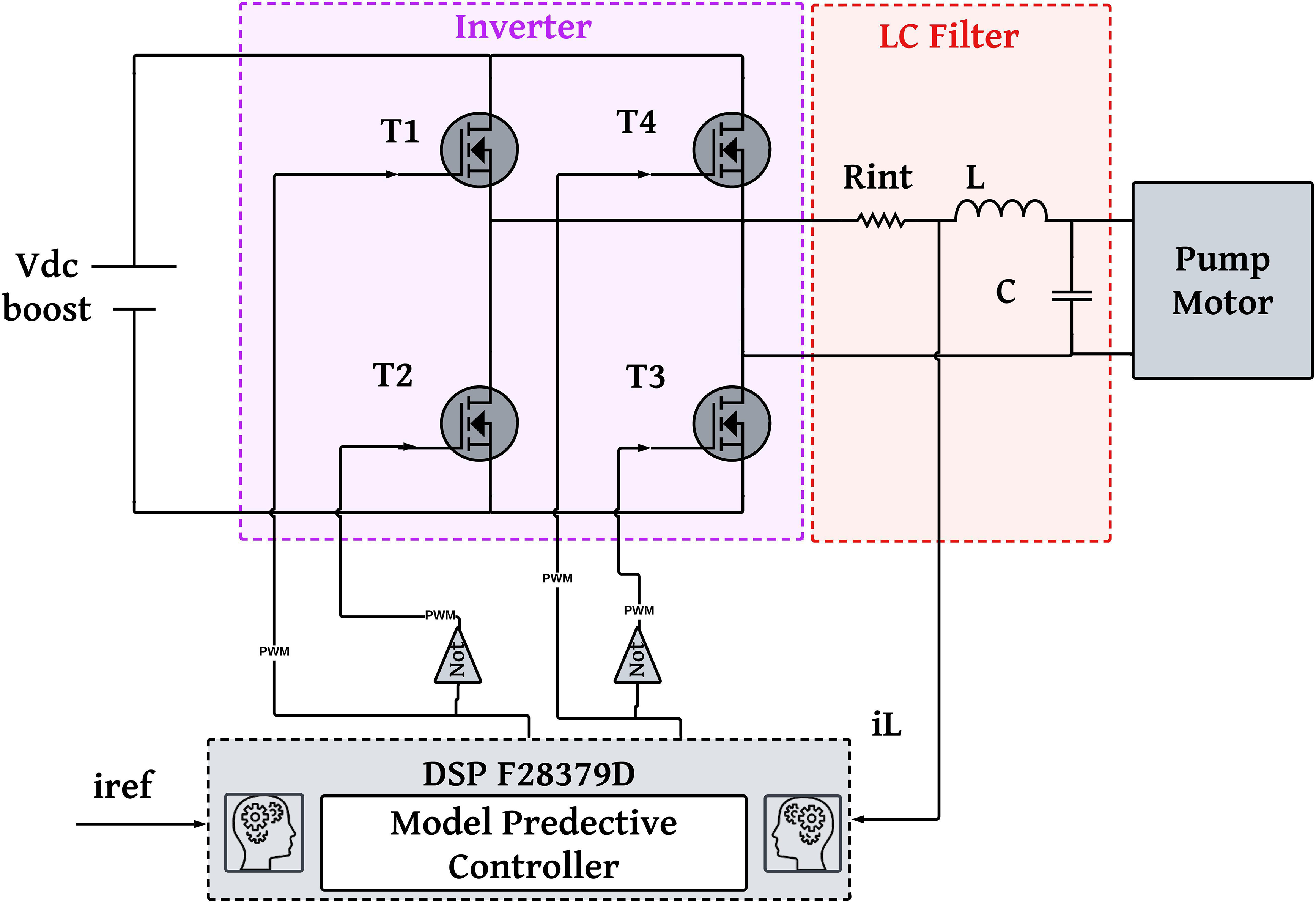
One of the significant advancements in vehicle-to-grid (V2G) technology pertains to the design of inverters for V2G systems. These inverters must demonstrate high efficiency and be capable of operating either as standalone units or in grid-connected configurations. The fundamental inverter design is illustrated in Figure 3.
The switching functionality in the circuit is facilitated by solid-state components denoted as T1–T4, which can include transistors, IGBTs, and MOSFETs. The output generated by the inverter produces AC voltage while maintaining a zero DC component. However, some level of harmonics persists within the output, necessitating the incorporation of a low-pass filter to attenuate high-frequency harmonics. These harmonics can lead to issues such as compromised power quality, equipment deterioration, and waveform fidelity problems in the inverter output. Figure 4 illustrates the structure of the MPC. Additionally, it is crucial that the inverter's output aligns well with the grid system's requirements.

MPC for inverter.
The summarized steps of the MPC are as follows:
Develop a model for the voltage vector at the inverter's output side. Construct a model for the load voltage. Specify a quality function, denoted as G.
The MPC process involves the following steps:
Utilize Vc(k + 1) as the measured load voltage value and Employ a predictive model of the load voltage to determine all potential values of the load voltage at the subsequent time step. Compare these values to ascertain the switch state corresponding to the minimum G value.
The output voltage can be determined based on the DC link voltage and VSI switching states, as outlined below:

The next equation demonstrates a discrete-time representation of the load voltage:

The equation used for predicting the load voltage is:

The MPC method utilizes a system model, DC link voltage, and inverter switching states to anticipate the future filter voltage value. Based on this data, the controller selects the optimal switching state, which is then applied to the board's switches. The predicted output voltage can be expressed as follows, with Ts representing the sampling time value of the controller. To implement the optimal switching signal in the system, all predicted filter voltages are compared with the filter reference voltage using a cost function, denoted as G.

The algorithm is outlined with the following sequential steps:
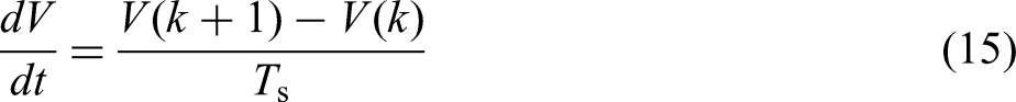
Initialize the parameters with specific values: The equivalent resistance and inductance values are set to 0.01 ohms and 6 mH, respectively. The sampling time is defined as 10 microseconds, and the optimal cost function value is initialized as infinity. Estimate current vectors and predict the filter voltage at the next instant (k + 1) using equations (15) and (16). Calculate cost functions using equation (17). Finally, select the minimum G value along with the corresponding switching signals.
This enhanced section aims to provide a more detailed and efficient explanation of the V2G inverter design and its operation within smart home energy systems and EV integration.
Results and discussion
This experimental setup illustrates a comprehensive system designed for the implementation and testing of a novel PV charging method for EVs. The system integrates a MPC for the DC–AC inverter and a hybrid ANN–GWO for the DC–DC converter to manage energy conversion in PSC.
The PV Installation shown at the top of Figure 5 consists of 8 solar panels, each equipped with blocking and bypass diodes to manage energy flow and minimize losses due to shading. These panels are connected to a solar inverter that converts the DC power generated by the PV cells into usable AC power for EV charging.

Experimental setup for solar-powered EV charging system using MPC and ANN–GWO control techniques.
At the heart of the system lies a Texas Instruments DSP F28379D microcontroller, which runs the MPC algorithm. The MPC optimizes inverter switching to minimize THD, reducing it from 2.56% to 1.56%. In the same context, the ANN–GWO algorithm is implemented for MPPT under PSC conditions. This method ensures that the system can track the global maximum power point (GMPP) more quickly and accurately compared to conventional techniques, increasing power output efficiency.
The experimental platform also includes oscilloscope channels for monitoring the systems performance in real-time, ensuring precise measurements during testing. The EV model used here is a scaled prototype to simulate the charging process using the real-time data acquisition and control system. Overall, this setup demonstrates a powerful combination of advanced control algorithms and real-time testing on the DSP microcontroller to validate the efficiency of solar-based EV charging systems under challenging environmental conditions.
The dynamic response of the PV power output, optimized using an ANN combined with the GWO, is illustrated in Figure 6. This figure depicts the power output, measured in Watts (W), against time in seconds, highlighting the structured and controlled behavior of the PV system under various conditions. Initially, the PV power shows a rapid increase, reaching a peak value of 150 W within the first 0.2 seconds. This swift response emphasizes the effectiveness of the ANN–GWO model in quickly achieving optimal power levels under fluctuating conditions. The benefit of using the ANN lies in its ability to minimize ripple, overshoot, and response time, ensuring a smooth power output even under PSCs. As time progresses, the system undergoes controlled step-down transitions, each followed by a stable power output phase. Around 40 seconds, the power smoothly decreases from 130 W to 100 W, demonstrating the model's precise control over power reduction while maintaining system stability. Another regulated drop occurs around 78 seconds, with the power adjusting from 100 W to 60 W. The final transition at 115 seconds further highlights the ANN–GWO's effectiveness, as the power reduces from 70 W to approximately 60 W with minimal oscillations. The zoomed-in insets within the figure offer a closer view of these transitions, underscoring the robustness of the ANN–GWO model in managing PV system power output. Each power level change is characterized by minimal overshoot, reduced ripple, and quick settling times, showcasing the model's high efficiency and reliability. In summary, the ANN–GWO optimization method ensures consistent and controlled PV power output, smoothly adapting to variations over time while maintaining high performance and stability. The use of ANN is particularly beneficial in minimizing ripple, overshoot, and response time, making it highly suitable for applications under PSCs compared with differences studies such as depicted in Table 1.

Photovoltaic (PV) power output.
Comparison of MPPT methods.

Explanation of results presented in Table 2:
Scenario 1 (No Shading):
The system achieves near-ideal efficiency (99.98%) and tracks the maximum power with a minimal tracking time of 0.02 seconds. The system exhibits high power tracking accuracy with no shading interference. Scenario 2 (2 Panels Shaded):
Despite partial shading, the system retains 96.12% efficiency, with only 3.88% power loss. The tracking time increases slightly to 0.05 seconds, which is still significantly better than traditional methods, and the power tracking accuracy remains high at 99.56%. Scenario 3 (4 Panels Shaded):
In this case, the efficiency drops to 92.45% with a power loss of 7.55%. However, the tracking time of 0.08 seconds and the accuracy of 98.35% still show the superior performance of the proposed method compared to conventional MPPT algorithms. Scenario 4 (Severe Shading):
Under severe shading conditions, the power loss increases to 14.37%, but the system still tracks the GMPP with an accuracy of 97.50% and a tracking time of 0.12 seconds, which is impressive under difficult conditions.
Power tracking performance under different scenarios.
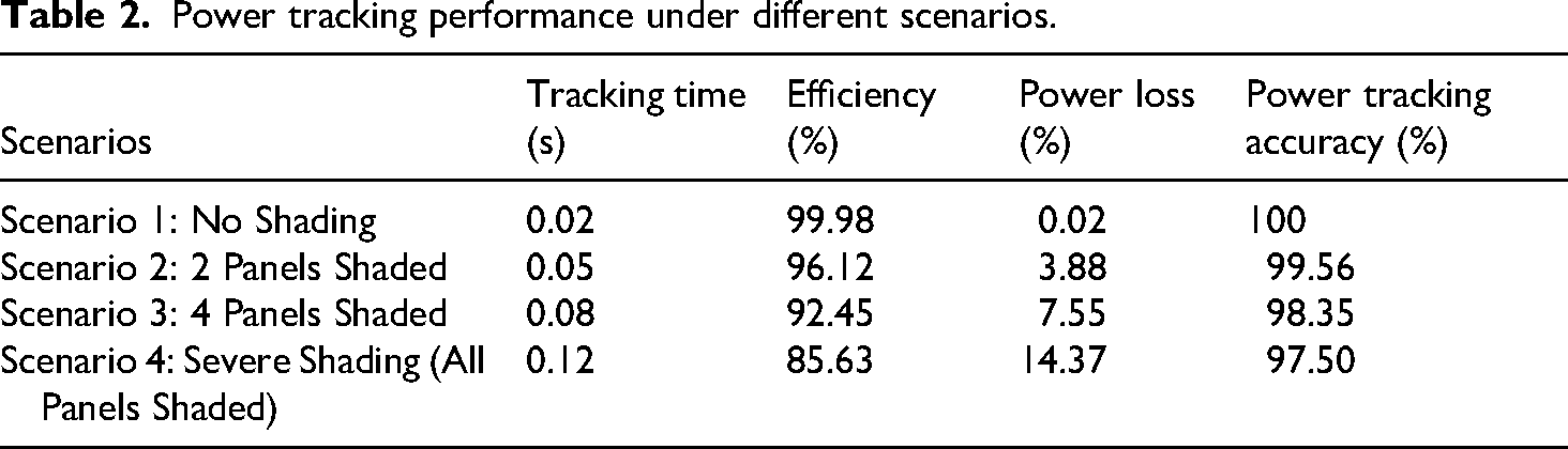
These performance metrics clearly demonstrate the effectiveness of the Hybrid ANN–GWO MPPT method under PSCs. The proposed method outperforms conventional methods in terms of both tracking speed and power extraction efficiency, even under severe shading scenarios. The high power tracking accuracy further highlights the robustness of the method in real-world applications, ensuring stable and efficient charging for EVs in residential and microgrid-based systems.
The proposed ANN–GWO MPPT approach exhibits enhanced efficacy relative to traditional MPPT techniques. Table 2 indicates that it attains the quickest response time (0.02 seconds) and the highest efficacy (99.98%), markedly surpassing conventional approaches like P&O, PSO, and FLC. These enhancements are essential for optimizing energy extraction from solar systems, particularly under partial shadowing circumstances (PSC). A primary advantage of the suggested method is its superior adaptation to PSC, a significant constraint in conventional MPPT techniques. In contrast to P&O and PSO, which demonstrate delayed responses and diminished tracking efficiency, ANN–GWO employs artificial intelligence and bio-inspired optimization to dynamically refine its tracking mechanism, thereby ensuring swift convergence to the GMPP. Furthermore, in contrast to existing heuristic algorithms like ABC and GWO, the suggested method demonstrates real-time applicability by effective hardware validation on the DSP F28379D platform, hence confirming its robustness for practical implementation.
Figure 7 illustrates the single-phase voltage profile over time, demonstrating the effectiveness of the MPC strategy implemented for grid voltage regulation, particularly under PSCs. The voltage, measured in Volts (V), is presented over a 150-second interval, showcasing the controller's capability to maintain a stable and consistent voltage waveform. Throughout the duration, the single-phase voltage remains sinusoidal, consistently holding an amplitude near 400 V. This stability underscores the MPC's precision in managing voltage levels, ensuring minimal deviations and maintaining overall system stability, even under PSC. The MPC's role is crucial in keeping the voltage steady, optimizing the system's response to variations caused by shading. Zoomed in section of the graph highlight critical moments at specific time intervals. For example, around 40 seconds, the voltage waveform shows negligible fluctuations, demonstrating the MPC's ability to swiftly and accurately respond to changes without compromising stability. Similarly, at approximately 78 seconds and 115 seconds, the voltage waveforms maintain a smooth sinusoidal pattern, further attesting to the MPC's robustness in ensuring consistent grid voltage under varying conditions. Overall, the performance of the MPC in regulating the single-phase voltage is highly commendable, as the system consistently stays within the desired voltage range, effectively mitigating potential voltage spikes or drops. The detailed insets within the figure provide clear evidence of the voltage's steady behavior, even during transitions, highlighting the reliability and effectiveness of MPC for grid-connected applications, especially when facing partial shading. In conclusion, the results demonstrate that the MPC strategy employed for voltage regulation is both effective and reliable, ensuring stable and well-regulated single-phase voltage throughout the grid integration process. This capability is critical for maintaining optimal grid performance and enhancing the resilience of PV-integrated systems. Figure 8 depicts the behavior of the single-phase current over time, managed by a MPC strategy for grid integration, particularly under PSCs. The current, measured in amperes (A), is shown over a span of 150 seconds, highlighting the precise control and stability achieved through the MPC approach. Notably, the MPC is designed to maintain maximum current output even when the system is subjected to shading, ensuring optimal performance.

The single-phase voltage profile.
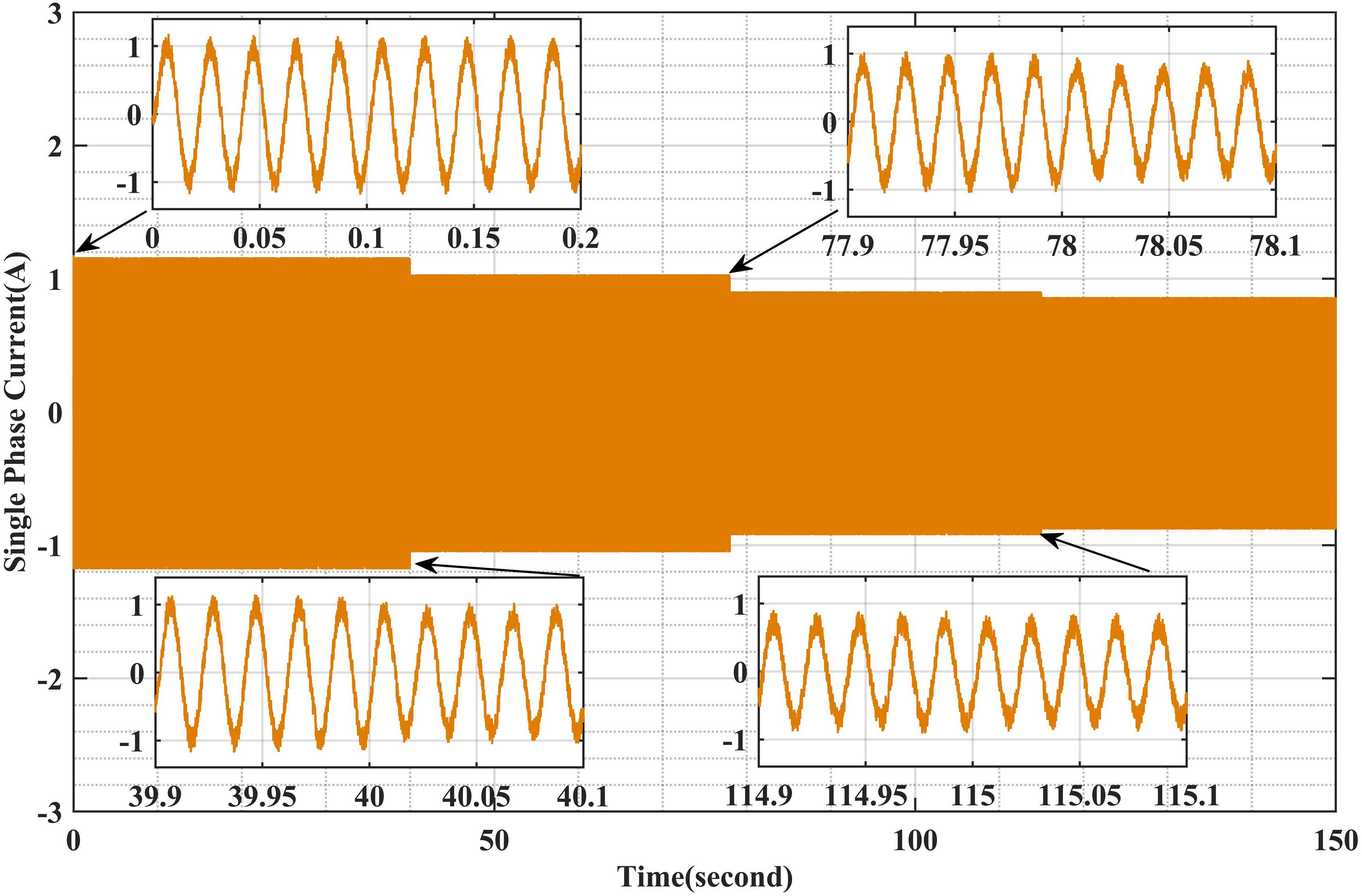
The single-phase current.
Initially, the single-phase current oscillates within a small amplitude, around 1 A, indicating stable operation from the outset. This stability is consistently maintained throughout the duration, demonstrating the MPC's capability to effectively manage current fluctuations, especially under varying shading scenarios. The MPC's role in minimizing disturbances and maintaining maximum current output is crucial for enhancing the reliability of the grid connection.
Zoomed-in sections of the graph emphasize key transition points at different time intervals. For example, around 40 seconds, the current waveform remains stable with minimal distortion, showcasing the MPC's ability to adapt to changes in system conditions without compromising performance. Likewise, at approximately 78 seconds and 115 seconds, the current continues to exhibit smooth, sinusoidal waveforms, further confirming the controller's robustness in maintaining grid stability and minimizing harmonic content.
Overall, the performance of the MPC in this setup is outstanding, as it ensures that the single-phase current stays within the desired range, effectively reducing potential harmonics or distortions. The detailed insets within the figure provide evidence of the current's smooth transitions and consistent behavior, highlighting the MPC's effectiveness in controlling grid-connected systems under PSCs.
In conclusion, the results demonstrate that the MPC strategy employed here is highly effective in maintaining a stable and well-regulated single-phase current, making it a reliable solution for grid-connected applications. Its ability to maximize current output and maintain system stability under shading conditions underscores its suitability for real-world implementation in PV-integrated systems.
Table 3 provides a detailed overview of the parameters of the boost converter used in the real-world experimentation setup. These parameters include specifications such as input voltage, output voltage, switching frequency, inductance, capacitance, and other key characteristics that define the boost converter's performance. By clearly outlining these parameters, the table offers a comprehensive understanding of the configuration and capabilities of the boost converter used during the experiments.
DC to DC boost converter parameters.

Table 4 outlines the parameters of the overall experimental system, including all the components and configurations employed to achieve the real-world results. This includes information on the PV system specifications, load characteristics, the control strategy implemented, and the environmental conditions under which the experiments were conducted. By presenting these details, Table 2 ensures transparency in the experimental process and helps to validate the accuracy and reliability of the results obtained.
Parameters of system in experimental mode.
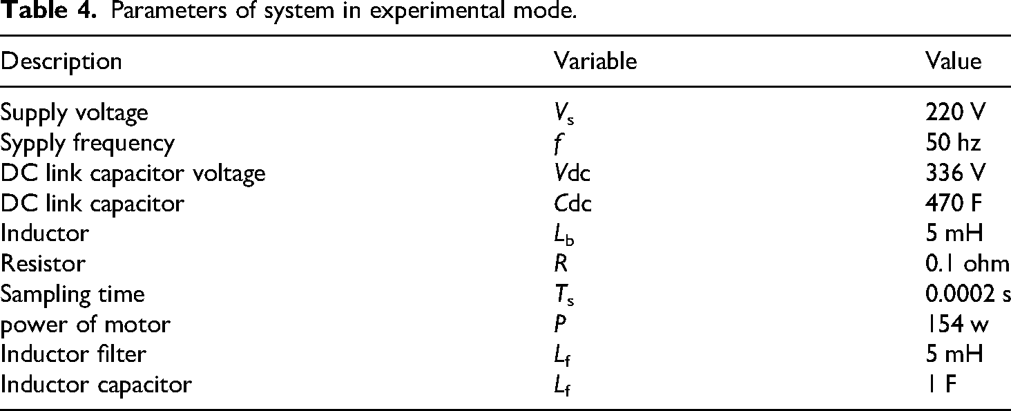
Table 5 highlights the effectiveness of the proposed algorithm in comparison to other existing algorithms. It demonstrates that our proposed method significantly outperforms others in terms of response time, achieving a faster response by reducing the time by 0.7 seconds. Moreover, the table shows that our approach delivers superior performance in terms of THD, achieving a remarkably low THD of approximately 1.56%. This is notably better than the THD value of around 2.56% found in the reference. 19 These results underscore the strength and efficiency of our proposed algorithm in optimizing system performance, ensuring both faster response and improved power quality in real-world applications.
Comparison table of algorithms.

Table 6 compares different control strategies, including PI, PI-Fuzzy, utilized PI, and MPC, based on response time and peak overshoot for DC voltage, DC current, and active power. While traditional PI and PI-Fuzzy controllers show moderate response times with higher overshoot, the utilized PI controller improves stability but at the cost of a longer response time. In contrast, the proposed MPC control significantly enhances system performance by achieving the fastest response time and minimal peak overshoot, demonstrating its superiority in optimizing transient response and stability.
Table of system performance comparison.

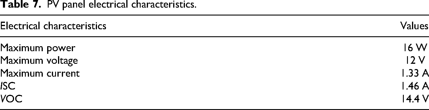
Table 7 provides a detailed overview of the parameters of the PV module used in the real-world experimentation setup.
PV panel electrical characteristics.
Conclusion
In conclusion, this study presents a comprehensive approach to improving the efficiency of solar-powered EV charging systems, particularly under PSCs. By integrating a hybrid ANN–GWO-based MPPT algorithm with MPC, the system achieves significant enhancements in voltage quality, response time, and overall performance. The proposed hybrid ANN–GWO algorithm effectively tracks the GMPP, reducing tracking time by up to 99.98% and improving dynamic tracking efficiency by over 9% compared to traditional methods. Additionally, the MPC approach minimizes THD to as low as 1.56%, demonstrating superior performance over conventional MPC strategies. Both simulation and real-world experiments confirm the robustness and effectiveness of the proposed system, representing a significant advancement in solar-powered EV charging technology. The hybrid ANN–GWO MPPT with MPC control offers promising applications in grid-connected EV charging stations, smart microgrids, and off-grid PV systems. Future work will focus on scaling the system for large-scale PV installations and incorporating adaptive thermal management to enhance performance stability under varying temperature conditions.
Footnotes
Nomenclature
Acknowledgments
Youness Hakam, as the corresponding author, was responsible for the conceptualization and writing of the original draft of this review article. Hajar Ahessab was responsible for the experimental results, and she conducted the literature analysis and structured the manuscript. Mohamed Tabaa contributed by revising the manuscript, refining the analysis, and providing valuable insights to enhance its clarity and coherence. Benachir Elhadadi contributed by revising the manuscript. Gaga Ahmed contributed by revising the manuscript. Both authors collaborated on the study's conception and design, ensuring a comprehensive and well-structured review.
Ethical considerations
Our institution does not require ethics approval for reporting individual cases or case series.
Funding
The authors received no financial support for the research, authorship, and/or publication of this article.
Conflicting interests
The authors declared no potential conflicts of interest with respect to the research, authorship, and/or publication of this article.