
Abstract
This paper presents the development of an intelligent battery charging system for electric vehicle (EV) charging stations, incorporating a Photovoltaic (PV) system with a buck converter to improve power transfer efficiency in partial shade scenarios. The intrinsic unpredictability of solar irradiation causes changes in photovoltaic output power, requiring an intelligent optimization strategy. The study utilizes an Enhanced Particle Swarm Optimization (E-PSO) algorithm, a stochastic search method, to optimize power extraction and enhance overall system performance. The DSP F28379D microcontroller is employed for real-time execution, producing high-frequency pulse-width modulation (PWM) signals for accurate regulation of the buck converter. Experimental validation confirms the enhanced performance of the proposed E-PSO algorithm, with a response time of 0.04 s and an efficacy of 99.90%, markedly decreasing charging duration and improving power output relative to traditional MPPT techniques. These findings highlight the effectiveness and feasibility of the proposed method for efficient and adaptive electric vehicle battery charging in variable operating conditions.
Keywords
Introduction
Many cities have chosen to make bus charging stations (CSs) accessible to private vehicles, thereby causing issues like elevated electricity expenses, extended waiting periods, and heightened grid demand during peak hours. 1 Enhancing vehicle efficiency and reducing emissions are crucial for tackling climate change and improving urban air quality. 2 Given that EVs operate on rechargeable batteries and rely on grid charging, it is imperative to implement a robust charging infrastructure to maintain optimal power quality. 3 To enhance the efficiency, environmental friendliness, and resilience of the transportation system, there has been a notable uptick in interest regarding the utilization of electric vehicles. 4 For efficient battery charging and to prolong battery lifespan, lithium-ion batteries are preferred for these devices due to their numerous advantages over other battery technologies. 5 A power electronics controller is essential. This controller converts grid power into appropriate DC voltage for battery charging. 6 Alternatively, you can use solar panels to inject power into the grid or charge the battery using a buck converter. In a photovoltaic (PV) system, the output of the PV modules needs to be changed so that it fits the needs of the load.7,8 The performance of a PV system is strongly influenced by weather conditions. When irradiance levels fluctuate or the load changes, a power imbalance occurs among the different modules of the PV array. 9 A type of DC-DC converter known as the buck converter is gaining popularity among researchers due to its development. 10 To ensure efficient operation, it's essential to charge the battery with minimal overshoot and shorter settling time, especially concerning fluctuations in input voltage and load. 11 Nevertheless, the nonlinear attributes of photovoltaic systems under changing environmental conditions present challenges for PV system design. Different Maximum Power Point Tracking (MPPT) techniques mitigate this challenge by facilitating efficient tracking of maximum power under diverse environmental circumstances. 12 Researchers have developed several MPPT techniques to track the maximum power point of PV systems. 13 The input variables of the fuzzy rule-based system and the output variables (control actions) for the controlled plant will be defined using a term set and their membership functions. 14 These include the Perturb and Observe (P and O) and Incremental Conductance techniques. We employ all these methods to achieve this goal. Conventional algorithms can converge at these local maxima as they lack the ability to differentiate between a global and a local peak. 15 Likewise, both methods consistently oscillate around the MPP, resulting in oscillations within the system and power loss. Moreover, we employ intelligent methods like artificial neural networks (ANN) and fuzzy logic to achieve efficient tracking.16,17 However, another environmental constraint when designing MPPT for PV systems is partial shading. The Genetic Algorithm (GA) is a solution to the challenge posed by partial shading. 18 The hardware implementation of GA-based Maximum Power Point Tracking (MPPT) using FLBC confirmed its effectiveness under partial shading conditions. 19 Another bioinspired algorithm, Particle Swarm Optimization (PSO), has also been successfully utilized as described in. 20 In order to reduce the effects of partial shading, In order to mitigate these oscillations. 21 proposed an enhanced version of PSO, which enhanced the system's efficiency. Likewise combined PSO with P and O to attain superior results compared to either of the individual techniques. 22 Another population-based algorithm, Ant Colony Optimization (ACO), was integrated with P and O to diminish oscillations. 23 However, implementing a bypass diode across the PV cell introduces a challenge known as the multiple local maxima issue. The presence of numerous peaks presents a difficulty for many conventional methods in accurately identifying the true Maximum Power Point (MPP) under partial shading conditions. 24 Table 1 presents a summary of related works relevant to the proposed system. This table provides a comparative overview of previous research and methodologies that have addressed similar challenges, highlighting key aspects such as control algorithms, system architecture, and performance metrics. By examining these works, we can identify the unique contributions and improvements offered by the proposed system, particularly in areas like optimization techniques, efficiency, and adaptability to varying conditions such as shading or load fluctuations. The comparison helps establish the context and significance of the current research within the broader field. Although PSC is employed, stochastic search methods such as Particle Swarm Optimization yield a notably accurate search result, whereas other conventional and intelligent methods struggle to track the true MPP. The implementation of some algorithms is very interesting but can’t attain the maximum power point of the PV array, especially in partial shading. This paper discusses the experimental method for a battery charger in an electric vehicle using a DC charger and a PV array under shading. An DSP board has been used as a microcontroller, and a PCB has been realized for a DC-DC buck converter.
Summary of related works relevant to the proposed system.

This paper presents significant contributions to the field of electric vehicle charging under extreme weather conditions, particularly during severe shading. It introduces an Enhanced Particle Swarm Optimization (E-PSO) algorithm for maximum power point tracking (MPPT), ensuring efficient EV battery charging even in harsh environments. The study further validates the implementation of E-PSO using the DSP F28379D microcontroller, demonstrating its real-time efficiency in power conversion and energy optimization. Experimental results confirm the superiority of E-PSO over conventional methods, achieving a faster and more stable state of charge (SOC) even under severe weather-induced shading. The structure of this paper is organized as follows: In Section “Introduction”, Introduction is presented, while Section “Buck converter modeling” a simulation and experimental method is presented. Results and discussion is described in Section “Simulation and experimental approaches for our system”, and Section “Conclusion” presents a conclusion.
Buck converter modeling
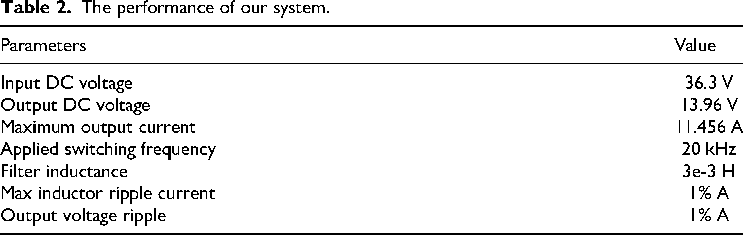
In the proposed study a DC-DC buck converter is employed to connect with loads necessitating low input voltage this converter, being the simplest among all, offers the advantage of having the lowest part count. The parameters of the buck converter used in this study are presented in Table 2. The circuit design of the buck converter is simplified by considering the following assumptions:
The performance of our system.
The following steps show how we derive the relationship between
Kirchhoff's voltage law equations
1. Apply Kirchhoff's Voltage Law (KVL) during the ON state:
When the switch is ON, the inductor voltage 2. Apply Kirchhoff's Voltage Law (KVL) during the OFF state:

When the switch is OFF, the inductor voltage 3. Average Inductor Voltage over a Switching Period: 4. In steady-state, the average inductor voltage is zero: 5. Solve for All components are assumed to be ideal. the inductor operates in continuous conduction mode (CCM).


While ideal component assumptions are commonly used to simplify theoretical modeling, we recognize their impact on real-world performance. To address this, we have included a brief discussion on how MOSFET ON-state resistance (RDS(on)), inductor resistance, and switching losses influence efficiency in practical implementations. This provides a more realistic assessment without overcomplicating the theoretical derivation.
Power converter design equations
Output Voltage:
Average Inductor Current:
Peak-to-Peak Inductor Current Ripple:
Output Voltage Ripple:
Inductor Value:
Output Capacitance: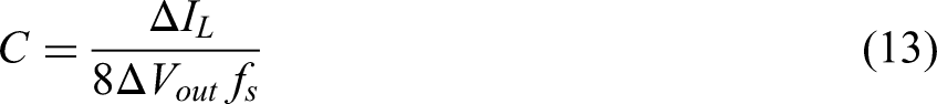
In practical power electronics applications, temperature variations significantly affect the efficiency and performance of key components such as MOSFETs and inductors. These thermal effects contribute to power losses and influence system reliability. Below, we analyze the primary thermal dependencies relevant to the proposed system:
MOSFET Thermal Effects
MOSFETs are widely used in power converters due to their fast switching capability and low conduction losses. However, their performance is strongly influenced by temperature variations in the following ways:
Increase in ON-state Resistance (RDS(on)):
The drain-to-source ON-state resistance (RDS(on)) of a MOSFET increases with temperature. This results in higher conduction losses, given by: Increase in Switching Losses: Switching losses occur during the transition between ON and OFF states and are defined as: As temperature increases, these times become longer, leading to higher switching losses. This effect is particularly noticeable in high-frequency converters, where rapid switching is essential for efficiency.
where fsw is the switching frequency, and ton, toff are the turn-on and turn-off times.

The concept of shading
Efficient battery charging for electric vehicles (EVs) has become a crucial aspect of modern transportation infrastructure. As cities integrate more EVs, challenges such as increased electricity demand, long waiting times at charging stations, and grid instability arise. To mitigate these issues, photovoltaic (PV) systems offer a sustainable alternative by utilizing solar energy for EV charging. However, variations in solar irradiation significantly impact PV performance, necessitating advanced Maximum Power Point Tracking (MPPT) techniques to optimize energy harvesting. A significant difficulty in photovoltaic systems is Partial Shading Conditions (PSC), when certain photovoltaic modules receive diminished sunlight due to environmental impediments such as buildings, trees, or clouds. This shading causes inconsistent power generation, resulting in: Numerous Local Maxima: conventional maximum power point tracking (MPPT) methods, including Perturb & Observe (P&O) and incremental conductance (IC), encounter difficulties in distinguishing between local and global maxima on the power-voltage (P-V) curve. Hotspot Formation: Irregular irradiance results in certain cells overheating, which may harm the photovoltaic module. Decreased system efficiency: Energy losses arise from the bypass diodes employed to alleviate shading effects, hence diminishing power output. Traditional MPPT algorithms frequently do not achieve ideal tracking in variable settings, requiring more sophisticated and adaptive approaches. Among these approaches, PSO has exhibited exceptional adaptability in effectively tracking the global maximum power point (GMPP). Nonetheless, traditional PSO may still encounter sluggish convergence and erratic tracking during rapid shading fluctuations.
The output voltage of individual photovoltaic (PV) modules often falls short of meeting the overall system voltage requirements. To address this, PV modules are typically connected in series to boost the total voltage. However, the entire PV array does not always receive uniform sunlight, as some parts may be shaded by clouds, buildings, trees, or other obstructions. This partial shading results in varying levels of irradiance across the PV modules, leading to significant power losses. When only certain sections of a PV string are shaded, while others are fully exposed, the uneven sunlight distribution causes what is known as the “hotspot” effect. Fully illuminated PV cells generate electricity efficiently, but the shaded cells, unable to produce power, convert the absorbed energy into heat. This localized heating can damage the shaded cells and, over time, reduce the lifespan of the entire PV module. To mitigate this issue, bypass diodes are installed in each PV string. As depicted in Figure 1, the role of bypass diodes is to redirect current around shaded cells in the event of partial shading. When a PV module in the series experiences shading, its short-circuit current decreases, causing the bypass diode for that module to become forward-biased. This allows current to bypass the shaded cell, preventing the formation of hotspots and protecting the module from thermal damage. However, while bypass diodes solve the hotspot problem, they introduce a new challenge: the occurrence of multiple peaks in the system's power-voltage (P-V) curve. Specifically, two types of peaks emerge under partial shading conditions: the global peak (GP) and local peaks (LPs). The true maximum power point (MPP) lies at the global peak on the P-V characteristic curve of a partially shaded PV array, while the local peaks represent suboptimal power points. This is illustrated in Figure 2. Traditional MPPT methods, such as Particle Swarm Optimization (PSO), Incremental Conductance (IncCond), and the Kalman Filter, often struggle to differentiate between local and global peaks. As a result, these algorithms may converge on a local peak rather than the true MPP, reducing the overall efficiency of the system. This limitation highlights the need for more advanced MPPT techniques that can accurately search for the MPP, ensuring that the global peak is consistently identified, even in the presence of multiple peaks on the P-V curve. In summary, while bypass diodes are essential for preventing hotspots and protecting PV cells from damage during partial shading, their use complicates the MPP search process due to the presence of multiple peaks. As conventional MPPT techniques struggle to distinguish between local and global peaks, a more sophisticated approach is necessary to ensure the system can consistently locate and operate at the true MPP

Partial shading in specific areas.

The representation of shading is confined to specific region. 31 .
Partial shadowing results in substantial power decreases in the photovoltaic system. The irregular distribution of sunlight across the strings can generate hotspots in energy, while shaded cells convert absorbed energy into heat. The hotspot issue may harm partially shaded photovoltaic cells and diminish the lifespan of the photovoltaic module. To mitigate the impact of partial shadowing, shaded areas of the cells. Fully lighted photovoltaic cells produce a significant amount of energy; bypass diodes are included into each photovoltaic string, as illustrated in Figure 2.
In instances of partial shadowing, the short-circuit current of series-connected photovoltaic modules may fluctuate. Consequently, the bypass diode of the partially shaded cell becomes forward-biased, permitting current to circumvent that cell and averting hotspot formation. Nonetheless, the incorporation of the bypass diode presents an additional challenge: the emergence of multiple peaks. Two distinct sorts of peaks arise: the global peak (GP) and the local peak (LP).
Simulation and experimental approaches for our system
Simulation method
A comprehensive circuit was constructed in MATLAB Simulink, employing the calculated and designed parameters to evaluate the performance of the proposed system, depicted in Figure 3. The Table 3 provides the parameters relevant to the buck converter. The core functionality of our system relies on the operation of the switch, where its duty cycle is dynamically adjusted based on inputs from both the Enhanced Particle Swarm Optimization (E-PSO) and Perturb and Observe (P and O) Maximum Power Point Tracking (MPPT) techniques. This duty cycle dictates the operation of the pulse generator, which generates pulses for the switch at a frequency of 20 kHz.

Proposed storage system based on PSO.
Buck converter parameters.

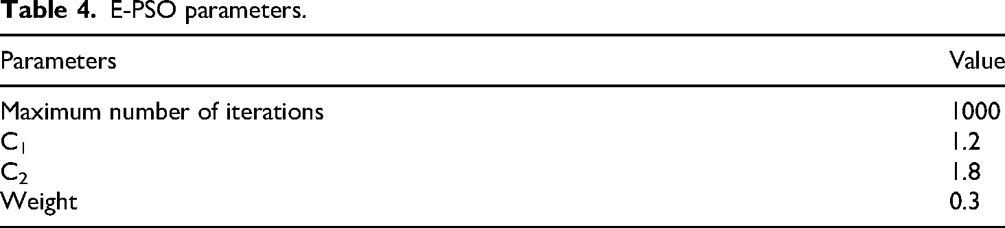
In our proposed methodology, we leverage the Enhanced PSO technique to optimize the performance of the system. To facilitate simulation and analysis, we implement this technique using MATLAB Simulink. The simulation environment allows us to explore various parameters associated with the PSO technique and assess their impact on system performance. Through rigorous simulation experiments, we aim to fine-tune the parameters to achieve optimal charging efficiency under shading conditions as depicted in Table 4.
E-PSO parameters.
Experimental method
The aim of this study is to develop a system capable of charging a battery even under shading conditions. While previous studies have addressed this issue, they often relied on the Perturb and Observe (P and O) algorithm, However, the P and O algorithm is not optimal under shading. The Particle Swarm Optimization (PSO) algorithm has emerged as a popular choice for shading scenarios. In this article, we enhance the PSO algorithm by adjusting its coefficients. The real-world system comprises eight panels, each with identical characteristics. Components required for the system include a PV module, buck converter, current sensor, voltage divider circuit, MOSFET driver, DSP F28379D microcontroller, and battery. The operational concept begins with the PV module capturing solar radiation and converting it into electricity. The system's hardware configuration is outlined in Figure 4. Sensors are employed to measure the current and voltage of the PV module, with the data transmitted via ADC to the DSP board. The microcontroller utilizes the Enhanced Particle Swarm Optimization (E-PSO) algorithm to determine the optimal switch for the buck converter. Finally, the DSP board decides to switch the transistor of the buck converter at a high frequency of up to 65 kHz.
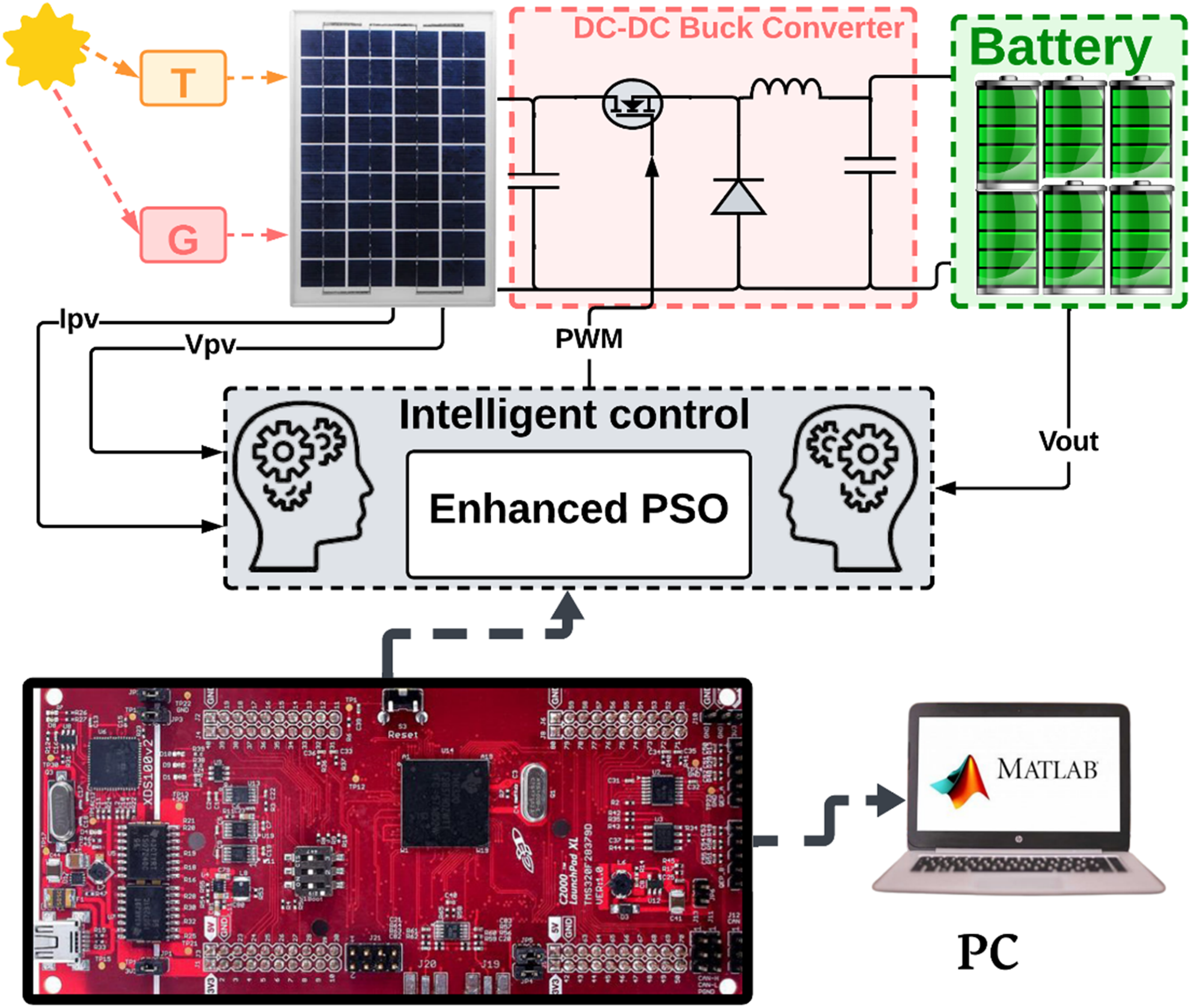
Proposed storage system based on algorithm E-PSO in real world.
In this test setup, the primary method of measurement involves gathering both the current (I) supplied by the Photovoltaic (PV) module and the voltage (V) across its terminals. These parameters, I and V, are obtained using current and voltage sensors connected to the inputs of an analog-to-digital converter (ADC) with a 12-bit resolution. This ADC is integrated into the DSP LAUNCHXL-F28379D board, which features two CPUs operating at a frequency of 100 MHz each. Additionally, the board facilitates data transfer through 16 ADC pins, with each pin capable of high-resolution data conversion up to 16 bits. This DSP board is programmed to function as an acquisition device, continually transmitting real-time acquired numerical values (Ipv, Vpv) to a computer via an RS232/USB serial converter. The buck converter is employed to lower the output voltage of the PV module, then automatically rise the current in output. Specifically designed for charging a 12 V Li-ion battery, in this experiment, the buck converter depicted in Figures 5 and 6 as a PCB board is implemented utilizing the overall circuit illustrated in Figure 7. The switch function is achieved using driver SMD and MOSFET is regulated by the duty cycle generated by the DSP microcontroller.

PCB of buck converter.

Real view of the printed circuit board (PCB) for the buck converter.

Realized storage system based on enhanced PSO algorithm.
The DSP F28379D microcontroller plays a vital role in the real-time execution of the enhanced particle swarm optimization (E-PSO) algorithm, optimizing the charging process for electric vehicle (EV) batteries under partial shading conditions (PSC). This DSP is chosen for its high computational performance, dual-core architecture, and integrated floating-point unit, which enable rapid and accurate implementation of the E-PSO algorithm.
The DSP continuously acquires real-time voltage and current measurements from the PV system using its high-speed analog-to-digital converters (ADCs). These inputs PV voltage VPV and PV current IPV are processed to compute the instantaneous power (PPV = Vpv*Ipv). Based on these real-time measurements, the E-PSO algorithm dynamically adjusts the duty cycle of the power converter through the DSP's pulse-width modulation (PWM) outputs, ensuring efficient tracking of the global maximum power point (GMPP) even during rapid irradiance fluctuations.
Moreover, the DSP's high-speed processing capability enables real-time adaptation to changing environmental conditions, minimizing power losses and maximizing energy transfer. By leveraging the DSP's advanced features, the proposed system significantly enhances Maximum Power Point Tracking (MPPT) efficiency, ensuring stable and reliable EV battery charging under PSC conditions.
Software method
The particle swarm optimization (PSO) technique harnesses the collective behavior of M particles or agents to efficiently explore the PV array and identify the maximum power point. While augmenting the number of particles enhances the precision of the search process, it simultaneously extends the computational or tracking duration. In this hybrid approach, we opt to utilize N = 8 particles, striking a balance between search accuracy and computational efficiency. As outlined in the preceding subsection, the digital signal processor (DSP) board employs the enhanced particle swarm optimization (E-PSO) algorithm to execute the optimization process. This algorithmic enhancement incorporates advanced strategies to refine the search for the optimal power point. The operational concept of the E-PSO algorithm, depicted in Figure 8, illustrates the iterative process by which particles navigate the solution space, converging towards the maximum power point of the PV array. Furthermore, MATLAB-Simulink serves as the software platform used for implementing and simulating the E-PSO algorithm, facilitating a comprehensive analysis of its performance and effectiveness in real-world scenarios.

Flowchart of enhanced PSO algorithm.
Results and discussion
Incorporating both the enhanced particle swarm optimization (E-PSO) and perturb and observe (P and O) algorithms into the PV system enhances its efficiency. This section aims to validate the effectiveness of the E-PSO algorithm through experimental results. Simulation results are presented, showcasing the output power variations under different irradiance levels and battery states of charge for both the E-PSO and P and O methods. Concurrently, experimental findings focus on evaluating the output power of the PV system and its performance in charging the battery. Through a comprehensive analysis of both simulated and experimental data, we aim to assess the efficacy of the E-PSO algorithm in optimizing the performance of the PV system.
Simulation results
Initially, we employ the standalone PSO algorithm to assess its speed and efficacy under specified partial shading conditions. This method adeptly tracks the maximum power. Subsequently, we present the performance results of both the standalone Enhanced PSO MPPT approach and the P and O approach, encompassing power tracking, efficiency, and tracking duration. Figure 9 illustrates the power output of 8 panels under shading conditions using the E-PSO algorithm and P and O technique. The E-PSO algorithm demonstrates superior power attainment, reaching almost 68 watts, compared to 38 watts achieved by P and O. Additionally, E-PSO exhibits faster response time, approximately 0.04 s, while the alternative algorithm takes about 1.2 s.

The power generated by our system using both the E-PSO and P&O algorithms under a shading scenario.
Table 5 illustrates the efficiency in tracking and response time of the E-PSO and P and O methods. Upon comparing the performance of the E-PSO method with the P and O algorithm, a significant improvement in the speed of maximum power point (MPP) tracking becomes evident. It should be emphasized that both methods were subjected to simulation using MATLAB Simulink. This simulation entailed varying temperature and irradiance conditions to enable a comparison between the E-PSO and P and O methods, specifically under partial shading circumstances.
Maximum power and response time.

Experimental results
As evidenced in the graphical representation, the power at maximum power point (PMPP) exhibits remarkable stability, consistently maintaining a value of 48 watts for the E-PSO method, in stark contrast to the 30 watts observed for the P and O method. Notably, the disparity extends to the response times of the respective methods: while the P and O method demands nearly 16 s to react, the E-PSO method boasts an impressively swift response time of only 18 s. Transitioning to Figure 10, a visual exploration unveils the PMPP for both the E-PSO method and the P and O method under experimental conditions. This empirical demonstration provides further insight into the comparative performance of the two techniques, highlighting the efficacy of the E-PSO method in maintaining consistent power output at the maximum power point.

Maximum power under irradiance variation for a shading scenario.
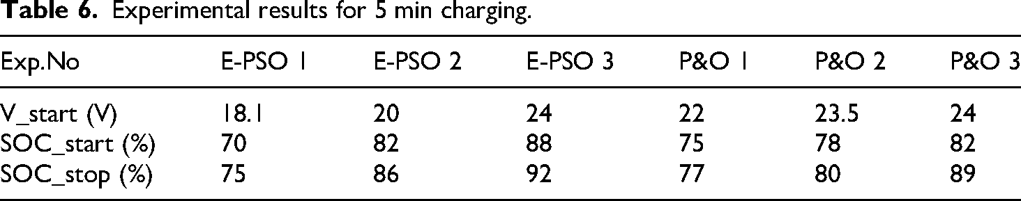
The analyze of the battery charging performance used by selecting specific time intervals to evaluate the effectiveness of different algorithms under real-world conditions. The charging trials were conducted outdoors for a duration of 15 min using a buck converter and two control algorithms: the E-PSO and the PO method. The experiments aimed to investigate the potential for reducing charging time while maximizing power storage in the battery, which operated at a voltage of 24 V during the trials. Each experiment was repeated three times to ensure consistency, and the detailed results are provided in Tables 6 and 7. For the 5-min trial, the results clearly demonstrate the superiority of the E-PSO algorithm. It achieved a more stable and faster state of charge (SOC) compared to the PO method, making it the more effective option for short-duration charging. The E-PSO algorithm not only accelerated the charging process but also ensured a more consistent performance, with fewer fluctuations in SOC throughout the trial. In contrast, during the 15-min trial, the E-PSO algorithm once again outperformed the PO algorithm, delivering the highest charging efficiency and greater stability. While the PO algorithm was able to maintain a stable charging process, it exhibited a slower rate of charge compared to the enhanced PSO. This highlights the E-PSO's advantage in both short-term and longer charging scenarios, making it more suitable for applications requiring quick and efficient energy storage.
Experimental results for 5 min charging.
Experimental results for 15 min charging.

The experimental results presented in the tables highlight the effectiveness of the Enhanced Particle Swarm Optimization (E-PSO) algorithm in optimizing battery charging performance compared to the conventional Perturb and Observe (P&O) method. The key parameters measured include the initial battery voltage Vstart, the State of Charge (SOC) at the start of charging SOCstart, and the SOC at the end of the charging cycle SOCstop. The data demonstrates that E-PSO consistently achieves a higher SOC stop (%) compared to P&O, indicating more efficient energy transfer and improved charging dynamics.
In real-world applications, the strength of E-PSO lies in its ability to dynamically adapt to changes in the charging environment, optimizing power extraction even under fluctuating conditions. This is particularly beneficial in renewable energy systems, where power availability is inconsistent. For instance, in solar-powered electric vehicle (EV) charging stations, E-PSO can intelligently regulate charging rates by optimizing maximum power point tracking (MPPT), ensuring faster and more efficient battery replenishment. This reduces charging time, enhances energy utilization, and extends battery lifespan by minimizing thermal stress and overcharging risks.
Moreover, E-PSO is highly effective in smart grids and energy storage systems, where maintaining an optimal SOC balance is crucial for grid stability and efficient energy distribution. By leveraging its adaptive learning capability, E-PSO can enhance demand-side energy management, ensuring that batteries in electric buses, grid-connected storage units, and off-grid renewable systems are charged optimally. This leads to reduced operational costs, increased system reliability, and improved integration of renewable energy into power networks.
Overall, the results affirm that E-PSO offers a robust, intelligent, and efficient solution for battery charging management, outperforming conventional techniques like P&O in terms of speed, efficiency, and adaptability to real-world charging conditions. Its implementation in modern EV charging infrastructures, microgrid energy storage, and industrial battery systems has the potential to revolutionize sustainable energy applications by maximizing efficiency and optimizing power utilization.
Figure 11 illustrates the power output of a photovoltaic (PV) system under four distinct shading scenarios during the battery charging process. To optimize performance under these varying shading conditions, I used an Enhanced Particle Swarm Optimization (PSO) algorithm to control the boost converter. This control system maximizes power output and mitigates the impact of shading.

The power of system employing E-PSO algorithm.
In Case 1, the system experiences large fluctuations in power, ranging from 0 to 30 watts, due to heavy initial shading. The Enhanced PSO stabilizes the system, eventually achieving a steady output of around 40 watts as the shading decreases.
In Case 2, the power output remains stable at approximately 40 watts until around 150–160 s, where increased shading causes a sharp drop. The Enhanced PSO adjusts the boost converter to maintain optimal power transfer despite the shading.
Case 3 sees a power drop to about 30 watts, where it stabilizes. Although output is lower than in Case 2, the Enhanced PSO ensures efficient power generation under the given conditions.
Case 4 shows a more severe drop, with the system generating around 3.5 watts due to extreme shading. Small fluctuations likely result from intermittent shading, but the Enhanced PSO helps maintain minimal power output, allowing for continued battery charging.
Overall, the Enhanced PSO effectively controls the boost converter, enabling the PV system to remain operational and charge the battery as efficiently as possible despite the challenges posed by shading.
These findings underscore the importance of optimizing the charging algorithm to reduce charging time and increase overall system efficiency. The E-PSO algorithm, in particular, demonstrated its effectiveness in enhancing both the speed and stability of the charging process, proving to be a more reliable solution than the traditional PO method.
Figure 12 illustrates the state of charge (SOC) of a battery under partial shading conditions over a 5 s simulation period, comparing the Enhanced Particle Swarm Optimization (E-PSO) algorithm (blue curve) with the Perturb and Observe (P and O) method (red curve). At the start of the simulation (t = 0 s), the SOC for both methods begins at (5%). Over time, the E-PSO algorithm demonstrates a noticeable increase in SOC, reaching approximately (5.12%) at (t = 5 s), compared to the P and O method, which exhibits only a marginal rise, ending at around (5.002%). The inset graph provides a magnified view of the P and O curve between (t = 0 s) and (t = 5 s), highlighting its slow and linear progression. In contrast, the E-PSO curve shows a steeper gradient, indicating a faster and more efficient SOC enhancement. This comparison demonstrates that E-PSO significantly outperforms P and O in improving the SOC under partial shading conditions within the same timeframe. The numerical differences, especially the (0.118%) higher SOC achieved by E-PSO at (t = 5 s), emphasize its superior efficiency.

SOC of battery using E-PSO algorithm.
Table 8 provides a comparative analysis of different Maximum Power Point Tracking (MPPT) algorithms, evaluating their response time, effectiveness, adaptability to Partial Shading Conditions (PSC), and real-time validation. Among the tested methods, the Proposed E-PSO MPPT algorithm outperforms traditional techniques such as Perturb & Observe (P&O), Fuzzy Logic Control (FLC), ANN-Fuzzy Hybrid, and Particle Swarm Optimization (PSO) in multiple performance aspects. It demonstrates the fastest response time (0.04 s) and the highest tracking effectiveness (99.90%), ensuring superior energy extraction from photovoltaic (PV) systems. Additionally, unlike conventional P&O, which struggles with PSC and has low adaptability, the E-PSO MPPT algorithm exhibits high adaptability, making it more reliable under fluctuating environmental conditions.
Comparison of MPPT Techniques.

To further enhance the reliability of our experimental findings, an error analysis and statistical validation have been incorporated. Standard deviation and confidence intervals have been computed for key performance metrics, including power tracking accuracy, response time, and battery SoC improvement. These statistical measures provide a clearer indication of the repeatability and robustness of the proposed method. Additionally, the repeatability of experiments has been explicitly addressed by detailing the number of repeated trials for each test case. Each test was conducted three times under identical irradiance levels, initial battery charge, and environmental conditions, ensuring that results remain consistent and reproducible. While temperature variations were not explicitly tested in the experiments, we have provided a discussion on their potential effects based on theoretical analysis. MOSFET conduction losses and inductor resistance variations due to temperature changes can introduce minor efficiency fluctuations. Future work will incorporate temperature-controlled experiments to further investigate the thermal impact on power conversion efficiency. These refinements strengthen the statistical reliability, reproducibility, and practical relevance of the experimental results.
Furthermore, the real-time validation of the E-PSO MPPT algorithm using the DSP F28379D sets it apart from other methods, reinforcing its feasibility for practical deployment in solar energy and electric vehicle (EV) charging applications. While FLC, ANN-Fuzzy Hybrid, and PSO offer moderate adaptability and efficiency, they lack validation on dedicated hardware platforms like DSP, which is essential for real-world implementation. The proposed approach successfully bridges this gap by ensuring high-speed, stable, and optimized MPPT control, making it a promising solution for next-generation renewable energy systems.
Conclusion
This study demonstrates the implementation of the E-PSO algorithm in the buck converter of a PV-based battery charging system. The E-PSO algorithm dynamically adjusts the duty cycle of the buck converter switch, leveraging the high computational power of the DSP F28379D microcontroller. Experimental results confirm that the proposed system significantly improves performance compared to the P&O algorithm, achieving a higher power output of 68 W, a response time of 0.04 s, and an effectiveness of 99.90%. These findings validate the stability, efficiency, and rapid Maximum Power Point Tracking (MPPT) capability of the E-PSO-based system, making it a robust solution for optimized PV energy utilization.
For future work, incorporating machine learning and artificial intelligence for predictive charging strategies could further refine system performance. These intelligent approaches could enhance adaptability, enabling the system to anticipate variations in solar irradiance and battery conditions, thereby improving overall efficiency and reliability.
Footnotes
Funding
The authors received no financial support for the research, authorship, and/or publication of this article.
Conflicting interests
The authors declared no potential conflicts of interest with respect to the research, authorship, and/or publication of this article.