
Abstract
Ground experimentation is an important method to verify the performance and quality of spacecraft structures. How to simulate the force and heat fields that a spacecraft may be subjected to during flight is a challenge for experiment design. In this paper, the static strength experimental method of spacecraft in the combined force and heat fields is studied. Furthermore, the coupling cases of the spacecraft during the flight process are simulated using an airbag and a resistive heater. Finally, it can be concluded that the accuracy of the proposed experimental method as well as the structural strength of the spacecraft can meet technical requirements during flight.
Keywords
Introduction
As a high-tech product, one of the important differences between spacecraft and other ground-based products is that during the flight process after launch, spacecraft will experience the test of a complex, harsh, and yet to be fully recognized atmospheric environment. Therefore, a large number of experiments need to be carried out on the ground to verify the reliability of spacecraft.1–3 The new generation of spacecraft is developing in a large-scale and complex direction, and the requirements for the structural stability of spacecraft during flight are also getting higher.4–6 Due to the influence of complex heat fields and outside air pressure loads on the outside surface of spacecraft during flight, the spacecraft may change and cause structural failure.7–9 Therefore, a series of studies on the experimental method of thermal deformation of structures under force and heat fields have been carried out. At present, there are mainly contact and non-contact measurement methods for structural high-temperature stress and strain testing. The contact electrical measurement technology using special strain gauges is the most commonly used one in terms of measurement accuracy, ease of use and research funds. The available high-temperature strain gauges mainly include the foil strain gauge, 10 the welded strain gauge, 11 the optical fiber, 12 and so on, which are selected according to the specific object of the test and the applicable temperature range. For consideration of cost and versatility, a foil strain gauge is used in this test.
Scheme design of structural static experiment under force and heat fields
Structural characteristics of spacecraft
The outside loads of spacecraft skin mainly include air pressure loads, concentrated loads of internal instruments and equipment, and so on. 13 The internal forces caused by the above loads include shear force, bending moment and torque.14–16 At the same time, extreme weather conditions, such as wind measurements, need to be considered. Therefore, in the case of outside loads, the connection position at the bottom of the spacecraft is subject to bending moments, and it is necessary to ensure the overall stiffness and strength of the spacecraft through the internal reinforcing rib. Therefore, the skin structure of spacecraft usually bears pressure and bending loads, and static strength has become a problem that needs to be fully considered in structural design. During the flight of a spacecraft, its skin structure bears not only the skin air pressure but also a high temperature. In order to study the influence of complex loads and high temperature fields on spacecraft structure, relevant ground experimental methods have been carried out in this article. The internal structure of the spacecraft in this experiment is shown in Figure 1.

Internal structure of the spacecraft.
Realization method of experimental heat field
In this experiment, it is necessary to provide a heat field for the spacecraft, which is about 200 °C. Generally, in the structural heat experiment, the structure is heated by three basic methods: heat conduction, heat convection and heat radiation. Considering the safety of the experiment, the experiment in this paper mainly considers the form of heat conduction.
The heat conduction is realized by the mutual contact between the heating element and the test spacecraft. The commonly used heating element is nickel-cadmium electric heating wire, which is insulated and densely woven by flexible high-silicon oxide cloth or ceramic sleeves. Figure 2 shows a common heating belt, which can be heated by energizing the electrode. Its working temperature can reach 1100 °C. The biggest advantage of heat conduction is that it can apply a uniform outside load to the heating belt and transfer the outside load through the heating belt without affecting its heating effect. The heating belt is generally controlled by the controller.

High silicon oxygen cloth and ceramic heating belt.
Considering the structure of the spacecraft and its characteristics of flying at high altitude, it can be known that its main heat transfer mode is heat conduction, and it also needs to apply pressure load to the skin of the spacecraft. Therefore, in this experiment, the heat field of the spacecraft will be simulated by the heat conduction mode of covering the spacecraft with hot wire.
Experiment scheme design
In general, the spacecraft structure consists of beams, reinforcing ribs, skin, and thermal insulation materials. The beam has the ability to support the structural stiffness. The reinforcing rib has the ability to locally enhance the stiffness and strength of the spacecraft. The skin and thermal insulation materials have the ability to protect the equipment or working load in the spacecraft from high temperatures and impact load damage.
During the flight process, different sections are subjected to different loads. The main bearing sections are the front surface, the front support surface, the main support surface, and so on, as shown in Figure 3. Among them, the front surface is the outer surface used to add load, located at the forefront of the component, which is perpendicular to the axis of the component. The front support surface is the support part of the component, and the outer surface is the conical surface of the component. In addition, the main support surface is the outer surface of the cylinder, and the back surface is the surface used to hold the component, which is also perpendicular to the axis of the component. In the process of high-altitude flight, when the spacecraft's flight speed does not exceed the maximum design value, the load shows the characteristics of axial pressure, shear force, and outside surface pressure. Consequently, the loads at the front surface, front support surface, and main support surface are respectively composed of pressure, shear force, and outside surface pressure. Therefore, the experimental verification of spacecraft flying at high altitude is transformed into: through the design of ground experimental cases, cover various combinations of representative load cases as much as possible.

Position of each surface in spacecraft.
In summary, the experimental scheme designed in this work is shown in Figure 4. The experimental system includes the experimental bench, the outside fixed tooling, the airbag, and the experimental spacecraft. The experimental bench is fastened to the ground. The spacecraft is fixed at the bottom of the experimental bench, which is used to simulate the connection between it and the rocket body in the actual situation. Before the experiment, install the spacecraft on the experimental bench. Then connect the hydraulic cylinder to the front surface of the spacecraft through tooling. During the experimental process, the spacecraft structure is heated to the specified temperature by the electric heating wire. Finally, the hydraulic cylinder is controlled to load axial force and shear force, and the measurement system obtains stress, temperature and other data.

Drawing of experimental scheme.
Implementation of force and heat field
Loading form of heat, pressure and outside load
The pressure load is generally applied by applying uniform pressure to the bearing surface. Usually, compressed gas, water, oil, and so on are used as the medium to act on the closed or enclosed space to realize the pressure load. The object of this experiment is the spacecraft, and the pressure is the air pressure on the outside surface. Therefore, the airbag is selected to simulate the outside air pressure load case during the flight process.
The pressure-loaded airbag used in the experiment is made of rubber with strong plasticity. The contact surface between the airbag and the spacecraft is designed to be similar to the shape of the loading surface, and the two surfaces fit perfectly during the experiment. The heating belt is wound on the surface of the spacecraft. During the outside pressure charging process, the outside fixed tooling is designed to constrain the deformation of the airbag during the loading process so that its pressure can be transferred to the surface of the spacecraft. When the inside of the airbag is pressurized, the position of the airbag is limited by spacecraft and fixed tooling, and the effective pressure is loaded. Figure 5 shows the pressure-loaded airbag. The airbag is designed with pressure control ports for charging and discharging and ports for pressure gauges.

Pressure loaded airbag.
In the experiment, it is necessary to apply horizontal and axial loads in different directions to different positions of the spacecraft to simulate the real loading cases in the flight process. Single-point loading equipment is installed in this experiment. Transfer the load from the loading actuator to the corresponding position of the spacecraft. During the loading process of each experimental working case, the size and direction of the fixed load shall be determined. The horizontal and axial loads on the spacecraft at different launch stages are simulated by completing several working cases. When horizontal and axial loads are applied, the loading points are distributed around the spacecraft and keep a fixed angle with the horizontal direction. The load transfer bar is used to connect the loading equipment and the loaded part, ensuring the accurate transmission of horizontal and axial loads. The experimental loading equipment is shown in Figure 6.

Experimental loading equipment.
Installation of overall experiment
In order to simulate the real connection between the spacecraft and the rocket body, the bottom of the spacecraft is fixed to the main beam of the experimental bench. The loading equipment is fixed to the experimental bench through the corresponding tooling. Sufficient strength and stiffness shall be ensured at all installation positions. The experimental installation is completed, as shown in Figure 7.

Installation of overall experiment.
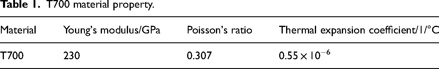
The material used for spacecraft skin is composite T700. This material is widely used in the aerospace field and has good heat resistance, corrosion resistance, high toughness and a high specific modulus. The main material properties of this material are shown in Table 1.
T700 material property.
Experiment process
The pre-inflation process of the airbag: After all the experiment equipment and spacecraft are installed, the experiment will begin. Firstly, pre-inflate the airbag to approximately 50% of the experiment value and check the pressure holding status.
Heating process: According to the experiment cases, heat the electric heating wire wrapped on the outer surface of the airbag until the required temperature is reached.
The standard inflation process for airbags: According to the experiment cases, continue to inflate the pre-inflated airbag to the required air pressure for the experiment cases.
Loading process: According to the experiment cases, control the experiment loading equipment to apply corresponding loads in different directions to the spacecraft.
Accuracy evaluation of static experiment
According to the needs of the experiment, paste the strain gauge at the corresponding position. Partial placement of the strain gauge is shown in Figure 8. After pasting the strain gauge and wiring, check each strain gauge. After checking, connect each strain gauge to the test system.

Pasting strain gauge on spacecraft.
Theoretical calculation of static experiment
The spacecraft is a nearly complete cylinder. Ideally, when the main support surface of the spacecraft bears shear force, the stress on the whole structure is pure bending deformation. In this pure bending case, the vertical stress value of each position of the spacecraft back surface can be calculated according to the theoretical calculation formula. The calculation formula is shown in Formula (1).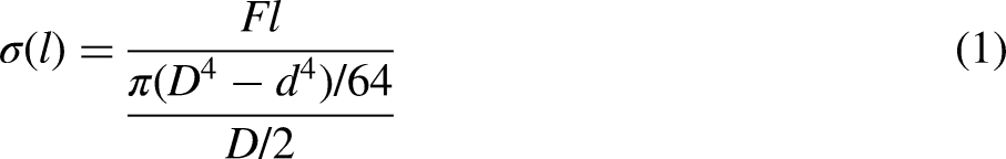

The meaning of each calculation parameter.
When the spacecraft is subjected to large wind measurements, the shear force of air acting on the main support surface is the main force acting on the spacecraft horizontally. The stress test data of the rear section in this case can be obtained through the experimental research on the established experimental platform. Treatment of the data, the experimental stress curve of the back surface and the theoretical calculated stress curve are compared, as shown in Figure 10.

Comparison between experimental stress and theoretical calculated stress.
Experimental accuracy evaluation
Based on the experimental and computational results in section ‘Theoretical calculation of static experiment’, the algorithm of numerical similarity and shape similarity is used to evaluate the experimental accuracy of spacecraft.
Numerical similarity is a numerical evaluation algorithm to measure the distance between different curves. The main calculation method is to consider two points in n-dimensional space for two curve sequences X = (x1, x2, …, xn) and X′=(x1′, x2′, …, xn′), and record the distance between two points as D(X,X′). The size of D(X,X′) directly reflects the similarity of these two curves. The mean value of the relative error of the values at different value points is calculated, which represents the distance between the two curves, as shown in equation (2):


According to equations (3) and (4), the numerical similarity and shape similarity of the spacecraft experiment and theoretical calculation are calculated, respectively. Based on the theory of multi-attribute index evaluation, it is more reasonable to calculate the comprehensive similarity of two similarity attributes by using the weight addition relationship. Therefore, the comprehensive similarity S between the spacecraft experiment and the theoretical calculation data sequence is expressed as equation (5):
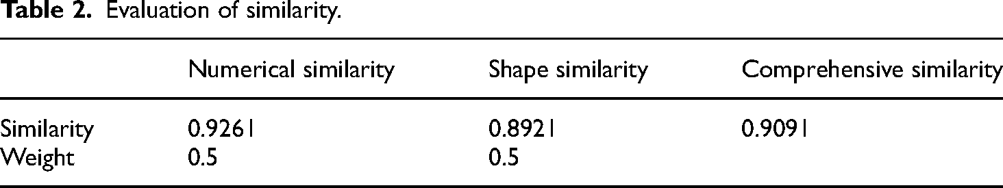
The experimental accuracy of the spacecraft is evaluated by using the results of the numerical similarity and the shape similarity of the curve. According to the experimental process of the spacecraft, it can be known that the entire experimental process is loaded at a uniform speed from the beginning to the end. Divide the two curves into eight line segments, and calculate the numerical similarity and shape similarity of the whole curve according to equation (5). Through calculation, the numerical similarity between the spacecraft experiment and theoretical calculation is 0.9261, and the shape similarity is 0.8921, as shown in Table 2. It is important to consider the influence of both numerical similarity and shape similarity on similarity, so the weight coefficient is taken as 0.5 and the similarity result of the comprehensive calculation is 0.9091.
Evaluation of similarity.
Analysis of force and heat experimental results
In this experiment, the static experiments of spacecraft in different loading cases are carried out. Test the stress and displacement of key positions (the key positions are 1001, 1002, 2001, 2002, 3001, 3002, 4001, and 4002), as shown in Figure 11.
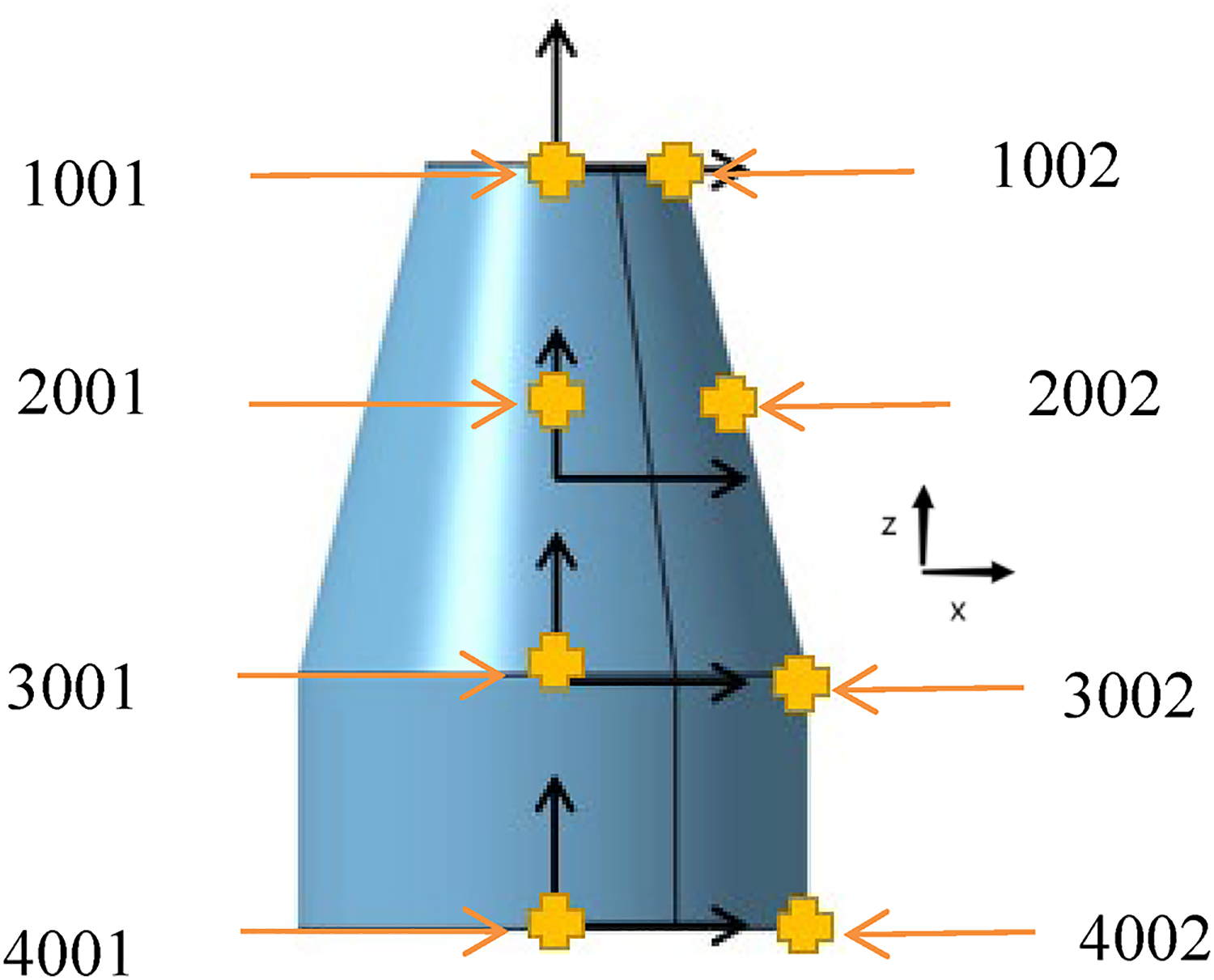
Key positions of the sensors.
Local strength case of front surface
The front surface of the spacecraft is an important load-bearing position that needs to be analyzed separately. According to the actual flight process, apply axial force and shear force to the front surface. In the experiment, load and measure step by step according to the table data, as shown in Table 3. Level 7 is the service load, level 9 is the design load and level 10 is the reliability load (1.4 times of the service load).
Load table of local strength case of front surface.

Gradual loading is completed according to Table 3, and experimental data (1001, 1002, 2001, 2002, 3001, 3002, 4001, 4002) can be obtained. The curve is shown in Figure 12. It can be seen from the figure that the stress at 1001 is the maximum, and its value is 362 MPa. On the x-axis, the displacement at 1001 is the largest, which is 5.8 mm. On the z-axis, the displacement at 2002 is the largest, which is −1.32 mm. In a word, the structure of the spacecraft can meet the design requirements in this case.

Stress and displacement curve of front surface in local strength case.
Force and pressure case without heat field
According to the actual flight process, apply axial force on the front surface, shear force on the front support surface and shear force on the main support surface. In the experiment, a uniform pressure is applied to the outside surface of the spacecraft through the airbag. The pressure and load are carried out in a gradual manner, as shown in Table 4. Level 7 is the service load, level 9 is the design load and level 10 is the reliability load (1.4 times of the service load). In the experiment, load and measure step-by-step according to the table data.
Load table of force and pressure case without heat field.

Gradual loading is completed according to Table 4, and the experimental data (1001, 1002, 2001, 2002, 3001, 3002, 4001, 4002) can be obtained, as shown in Figure 13. It can be seen from the figure that the stress at 1001 is the maximum and obviously greater than other values, and its value is 340.3 MPa. On the x-axis, the displacement at 1001 is the largest, which is 3.27 mm. On the z-axis, the displacement at 2002 is the largest, which is −1.27 mm. In a word, the structure of the spacecraft can meet the design requirements in this case.

Stress and displacement curve of force and pressure case without heat field.
Force and pressure case with heat field
Generally, there are insulation tiles outside the spacecraft, so the surface temperature of the spacecraft is about 200 °C. The experimental process in this case is as follows: First, apply uniform pressure to the outer surface of the spacecraft through the airbag. Then, control the device to heat to the temperature required by the experiment. Finally, the load shall be loaded to the specified value. The pressure and load are carried out in a gradual manner, as shown in Table 5. Level 7 is the service load, level 9 is the design load and level 10 is the reliability load (1.4 times of the service load). During the experiment, load and measure step-by-step according to the table data.
Load table of force and pressure case with heat field.

Complete the step loading according to the load table, and the experimental data (1001, 1002, 2001, 2002, 3001, 3002, 4001, 4002) can be obtained, as shown in Figure 14. It can be seen from the figure that the stress at 1001 is the maximum and obviously greater than other values, and its value is 350.2 MPa. On the x-axis, the displacement at 1001 is the largest, which is 3.28 mm. On the z-axis, the displacement at 2002 is the largest, which is −1.27 mm. In a word, the structure of the spacecraft can meet the design requirements in this case.

Stress and displacement curve of force and pressure case with heat field.
Conclusions
In this paper, the ground experimental method of force and heat field of spacecraft during the flight process is studied. The main research content is the structural reliability and stability experiment of spacecraft under the combined load of pressure and shear force, which mainly checks whether the spacecraft structure meets the design requirements under the coupling of force and heat field. The following conclusions can be drawn:
Through this experiment, we can know that this experimental method is operable and accurate for spacecraft. The strength and stiffness experimental results of the spacecraft are within a safe range, which can meet the design requirements. When there is a heat field, the maximum stress on the spacecraft will increase by about 2.9%. The heat field has little effect on the stiffness of spacecraft.
Footnotes
Acknowledgement
The authors are grateful to anonymous reviewers’ valuable comments and suggestions.
Author contributions
Bo Zang: conceptualization, methodology. Baokang Zhang: formal analysis. Yuhan Liu: resources, investigation. Guodong Zhou: visualization, writing—original draft. Huyi Yan: writing—review & editing. Yu Hou: supervision, project administration.
Declaration of conflicting interests
The authors declared no potential conflicts of interest with respect to the research, authorship, and/or publication of this article.
Funding
The authors received no financial support for the research, authorship, and/or publication of this article.
Author biographies
Bo Zang is senior engineer, director of the Environmental Testing Division of 508 Institute, director of the Testing Technology Branch of the Chinese Silicate Society, and member of the Spacecraft Environmental Engineering and Vacuum and Low Temperature Professional Groups of the Science and Technology Committee of the Fifth Academy of Astronautics and Astronautics. He mainly engages in research on static testing of spacecraft structures, vacuum thermal testing of spacecraft, and simulation technology for environmental testing. He has presided over the completion of multiple national key model large-scale static tests, improved new technologies for thermal testing of optical remote sensors throughout the entire process, and demonstrated the construction of environmental simulation testing equipment and facilities.
Baokang Zhang obtained a Bachelor's degree in Materials Forming and Control Engineering from North China Institute of Aerospace Engineering in 2009. In the same year he started working at the Beijing Institute of Space Mechanics & Electricity, conducting static testing research on spacecraft structures.
Yuhan Liu is an engineer and the head of structural static testing at 508 Environmental Testing Business Units, obtained a Bachelor's degree in Metal Materials Engineering from Shenyang University of Aeronautics and Astronautics in 2014. Mainly engaged in static testing of spacecraft structures, and has led and completed multiple large-scale static tests of national key models.
Guodong Zhou received the MS degree in Mechanical Manufacture and Automation from Inner Mongolia Agricultural University, China, in 2016. His current research interests include Spacecraft statics test technology and nondestructive testing technology.
Huyi Yan graduated from North China Institute of Astronautics Technology in 2009, majoring in Automotive inspection and maintenance specialty, and has been working in the field of static testing of spacecraft structures since 2010 at the Beijing Institute of Space Mechatronic Engineering.
Yu Hou obtained a Bachelor's degree in Aircraft Manufacturing Engineering from Nanjing University of Aeronautics and Astronautics in 2009, a Master's degree in Aircraft Design from Nanjing University of Aeronautics and Astronautics in 2016, and a PhD in Aircraft Design from Nanjing University of Aeronautics and Astronautics in 2021. He has been working as a lecturer at Nanjing Vocational University of Industry Technology since 2021. His current research interests include aircraft design, FEA and landing gear system.