
Abstract
Natural fibres have proven to be a potential alternative to replace synthetic fibres in some composite materials applications. However, drawbacks such as impregnation difficulties and the poor fibre–matrix interface limit the use of natural fibres in high-performance applications. This work proposes using an acrylic resin to coat the fibre surface to enhance the interfacial compatibility among fique fibres and polyester resin. Pull-out tests revealed an improvement in the interfacial shear strength of about 110% for coated fibres. Furthermore, nanoindentation test, Micro Raman spectroscopy and scanning electronic microscopy indicated that the acrylic resin eliminates the gap at the fibre/matrix interface seen in the uncoated fibres. Observed behaviour could be attributed to a better chemical bonding between the fibre and matrix and is also hypothesised that the elastic characteristic of the coating helps to transfer loads effectively from the matrix to the fibre.
Introduction
It is known that most natural fibres are hydrophilic. 1 This property limits their bonding with polymeric materials, thus preventing an effective load transference among the composite constituents, leading to poor mechanical performance. 2 Additionally, the natural fibres have an inherent high scatter in their mechanical properties3,4 posing difficulties in the design process.
Although these drawbacks are well recognised, natural fibres are attractive due to their low price, low environmental impact,5–7 good specific mechanical properties, good thermal and acoustic insulating characteristics, renewability and biodegradability. 8 Among the most common natural fibres used in composite materials are kenaf, hemp, jute, flax, ramie, sisal, pineapple leaf, coconut fibre, bamboo, silk and cotton. 9 Some natural fibres such as lino and bamboo have reached maturity in their development, obtaining technical fabrics used as reinforcement for some sports products, motorsports, bodywork, automotive and interior panels. 10 Moreover, natural fibres are currently actively researched in academic and industrial fields.
Fique fibre is a natural fibre from the leaf of a plant sown and widely cultivated in Colombia. It is scientifically known by the name of Furcraea, belonging to the Agavaceae family. 11 The fique fibres are obtained through a mechanical decortication which consists in separating the fibres in the cortex from the fique plant leaves. In this process, the juice is extracted, and then the fibres obtained are washed with abundant water. 11 The fique plant grows between 1200 and 1800 meters above sea level, with a temperature between 18 and 25°C. The maximum yield of this type of plant is obtained after four years of age. The cycle for obtaining fibres allows the birth of new leaves, which means that fique is an efficient renewable raw material. 11 The companies that transform fique fibres into ropes commonly use a soy oil solution (5 Wt.%) as a lubricant for the natural fibres avoiding the breaking and premature wear of the machines during the processing. A good amount of literature shows that the fique is a good candidate for replacing synthetic fibres, like glass fibres for some applications.12–14 Those studies are mainly devoted to chemical treatment effects on the mechanical properties of fique-reinforced composites. For example, Hidalgo et al. 15 evaluated the viability of manufacturing composite material reinforced with untreated fique fibres in mat form using epoxy resin and linear low-density polyethylene (LLDPE). The use of these fibres as reinforcement (20 Wt.%) in a composite increased their tensile strength in comparison with pure polymeric matrix; furthermore, two commercial parts were manufactured using a thermocompression process and resin film infusion for LLDPE and epoxy resin respectively, representing a new alternative for manufacturing biocomposites reinforced with fique fibres.15,16
However, there is a lack of studies regarding the interface nature between the fique fibre and the matrix.17,18 The only study devoted to the interface between fique fibres and a polymeric matrix was conducted by Mina et al.,1,19 they proposed an alkalinisation chemical treatment to modify the fique surface to increase the bonding at the interface with a matrix of several thermoplastic polymers. Pull-out and tensile tests revealed a positive effect of the fibre's treatment on the micro and macromechanical properties of the composites. Authors argue this is due to an improved interface between the fibre and the matrix. This is the same conclusion of many other authors,17,20,21 working on composites reinforced with natural fibres. However, a detailed analysis of interface micrographs of several studies18,20,22,23 of different natural fibre-reinforced composites reveals a gap between the matrix and the natural reinforcement meaning that the fibre adhesion is not necessarily improved. This allows us to hypothesise that most chemical treatments are not the only ones responsible for the increased strength and stiffness of naturally reinforced composites: chemical processes such as delignification could increase the failure strength and Young's modulus of the fibres and also its surface roughness leading to, no matter if there is or not an improvement of the interface, an increase in the failure strength of the composite with respect to composites with untreated reinforcements.
Mina 19 showed that the pull-out strength increased with the embedded length in a thermoplastic starch matrix; at 5 mm, the highest interfacial shear strength was found, around 2 MPa for treated fibres and 1.2 MPa for untreated ones. On the other hand, Ardila 24 evaluated the interfacial shear strength for a polyester/untreated fique system using pull-out test, the results show a mean value of 2.4 MPa using 5 mm of embedded length; however, the study does not allow for assessment of any other detail of the interface.
Therefore, the present work proposes to coat the fique fibre using a styrene-acrylic solution, expecting to eliminate the gap between the fibre and matrix and enhance their adhesion. Similar techniques, using epoxy, soy oil and other coatings, can be found in the literature.25,26
To the best knowledge of the authors, this combination of fique fibre/styrene-acrylic coating has not been previously investigated. The reason to use styrene-acrylic resin is its low cost compared with styrene resins, and the proven good results in other industrial applications such as paint, paper sizing machines, adhesives glass-fibre and secondary binder applications. This type of coating contributes to decreasing the hydrophilic character of fique fibre because it covers the surface and voids that absorb water and moisture.26–28 Mechanical, chemical and microstructural characterisations were carried out to explain the positive effect on the adhesion performance of the interface when fique fibres are coated.
Materials and methods
Raw fibres and coated fibres
Fique fibres were provided by Compañía de Empaques in Medellin, Colombia. 29 During the manufacturing process, individual fibres are joined through the chafed and spun processes, which leave some remnants and impurities. These fibres are then dried and packed in a coil and are referred to as ‘raw fibres’ (see Figure 1c).

The raw fibres were first combed to remove most of the impurities present at the fibre surface and to isolate uniaxial fibres. As combed fibres still have oil and other contaminants on their surface, to evaluate the influence of the washing process in comparison with raw-combed fibres, a group of fibres were washed in tap water at 80°C for one hour in a thermostatic bath Lauda Ecoline StarEdition model RE106. This procedure helps to remove some remnants and impurities on the fibre surface. Both groups of combed fibres, unwashed and washed, were dried in an oven at 80°C for 3 h to remove the moisture content. Then, they were stored for 12 hours in a desiccator before they were submitted to tensile tests or used for the manufacture of the samples for the pull-out tests. In summary, combed fibres will be in four states: washed (coated and uncoated) and unwashed (coated and uncoated).
As a matrix to manufacture pull-out test samples, a commercial resin reference Cristalan 847 was used. It is an unsaturated polyester resin provided by Andercol, 30 specially developed for the manufacture of pipes using glass fibre to reinforce polymers by filament winding process. 0.1% cobalt octoate and 1% MEK peroxide were used to harden the resin.
To coat the fibres, Ultracryl 101 a styrene-acrylic resin (30 Wt. % solids) was selected. Due to its high viscosity, it was necessary to dilute it in glacial acetic acid (Rotipuran 100%) in a weight ratio of 1:1. This solution allows an easy coating process promoting a uniform film on the surface of the fibres. The coating process was conducted via immersion of the fibres in the solution for 2 min, and then the fibres were placed vertically allowing to drain the excess of emulsion. The coated fibres were dried for 12 h at room temperature and, finally, in an oven at 80°C for 3 h. This process results in a coating of about 10 µm in thickness. 4
Tensile tests of individual fibres
The tensile tests were carried out in a Texturometer TA – XT2i with a speed of 10.2 mm.s−1. This equipment has a load cell of 50 Kgf and an accuracy of 0.1 g and 0001 mm in load and displacement, respectively. The tests were carried out at a temperature of 22.6 ± 0.5°C and relative humidity of 51.9 ± 1.2%.
The cross-section area measurement was conducted for each fibre tested using optical microscopy. The strain was calculated using the cross-head displacement, while Young's modulus was calculated using the slope of the elastic region up to 0.2% of strain.
The fique fibres properties were measured for individual unwashed and washed fique fibres with a gauge length of 50 mm using a cardboard substrate to fix them and then, to perform the tensile tests (see Figure 2). Five fibres were tested for each condition.

Cardboard mounting to conduct individual fibre tensile test.
Nanoindentations tests
The nanoindentation tests were performed on an IBIS Authority Fischer-Cripps with a Berkovich-type diamond tip in closed-loop mode. Area function was previously calibrated using fused silica and the Oliver and Pharr method. 31 It was scanned at a length of about 95 µm through the fibre-matrix interphase, a maximum load of 1 mN was used and a separation of 5 µm between each indentation was maintained. The Oliver and Pharr method was used to deconvolute the elastic modulus data assuming a Poisson's ratio of 0.4 for all the components. To measure the coating's elastic modulus, a small bulk cylinder of 5 mm in diameter and 3 mm in length was prepared.
Pull-out tests
Pull-out samples were prepared using a silicon-casted mould. The mould was cut using a laser cutting machine and had dimensions of 38 × 38 × 3.2 mm. The centre rectangle corresponds to the length to embed the fibre. The fibre is positioned in the mould as shown in Figure 3. The polyester resin was poured into the mould and, after 24 h, it was removed and cured for 3 h at 80°C. Finally, the samples were adhered to cardboard using an acrylate resin to fix the fibre (Loctite 495), a guide-line to centre the fibre was used to ensure the fibre's axial alignment.

3D model of the pull-out sample ready for testing with the silico-casted mould.
Pull-out tests were carried out at a temperature of 23.1 ± 0.5°C and relative humidity of 52.2 ± 1.5%. The sample was located in the middle of the clamps in the Texturometer to ensure total alignment of the fibres and the matrix. A speed of 10.2 mm.s−1 was used during the tests. Three fibres were tested for each embedded length.
Using the load-displacement data and embedded length the interfacial shear strength was calculated according to the mathematical model in equation (1):
32

To calculate the critical length of the fibre, the model proposed by W. Callister
33
was implemented, equation (2):
To guarantee that the failure process occurs by pull-out and not by fibre fracture, preliminary tests with different embedded lengths were conducted as proposed by Mina et al. 19 Lengths between 2 and 4 mm obtained 100% of success rate in the pull-out tests; however, these lengths resulted in lower interfacial shear strength in comparison with a length of 5 mm; 5 mm of embedded length produced around 66% success rate of interfacial fracture, avoiding fibre fracture and produces the highest interfacial shear strength. Therefore, a 5-mm embedded length was selected to analyse the following sections. The use of this length ensures an optimal critical length of the fibre, which is defined depending on the interfacial shear strength.
The pull-out test data analysis was carried out using a one-factor (type of fibre) analysis of variance – ANOVA using Minitab 19 statistical software. The confidence level used in the software was 0.1. This was chosen due to the high variability in the physical and mechanical characteristics of the natural fibres.
Micro Raman spectroscopy
Confocal micro-Raman spectroscopy analysis was performed using a Horiba LabRam HR confocal spectrometer. A solid-state 785 nm laser and a 600 gr.mm-1 grating were used. The spectra were taken in a range of 200–4000 cm-1 with an acquisition time of 15 s and eight accumulations. To find and focus the area of interest in the sample, an optical microscope with a 100X magnification was used. For these parameters, according to the manufacturer the radiation area of interaction was estimated to be about 1060 nm in diameter. 34
The software used for both data acquisition and spectra processing was LabSpec6. The micro-Raman spectroscopy tests were carried out at a temperature of 21°C with a relative humidity of 38 ± 2%. For this evaluation, metallographic cross-sections of composite samples were prepared according to the standard ASTM E384 – 17. Figure 4 shows the interfacial zone obtained for both washed uncoated and coated fibre embedded in a polyester resin.
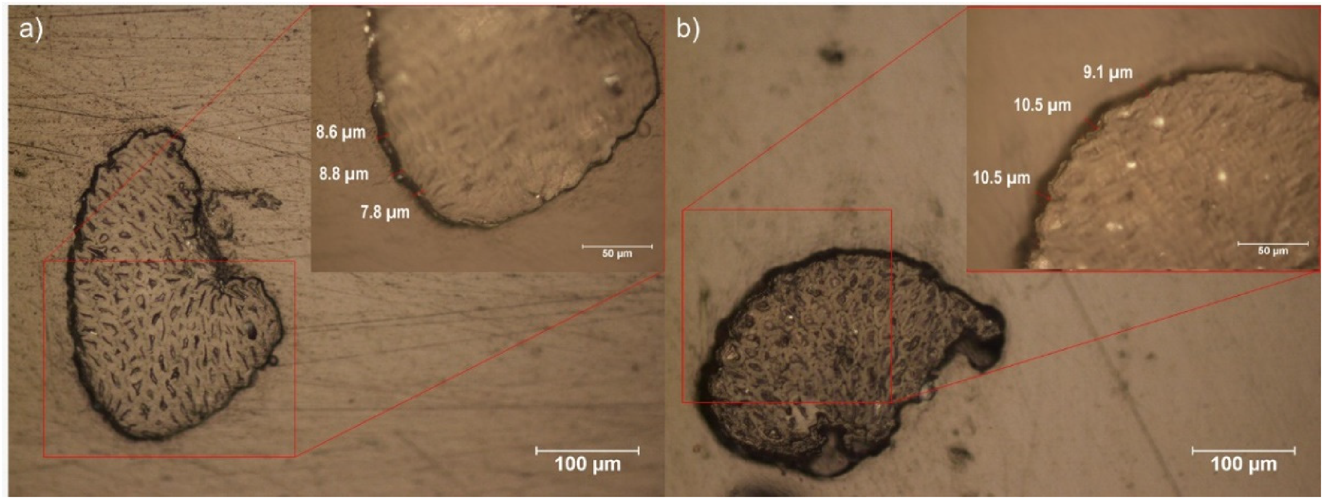
Interfacial zone focused using the optical microscopy of the micro-Raman spectroscopy. (a) Washed and (b) Washed and coated fique fibre.
Microscopy analysis
As shown in Figure 5, to measure the cross-section area, the fibres were held with a double clip hook and analysed in a stereoscope Nikon SMZ1500 with a light source NI – 150. Software NIS Elements was used to capture the micrographs, and then, software Image J was used to measure the cross-section area. Cross-section measurements were taken at the end of the embedded length for pulled-out fibres while for the fibres evaluated in tension the measurements were made near to fracture zone. For the alignment of the fibres with respect to the light axis, a plastic tweezer was used to avoid touching the interest zone.

Double clip hook use to take cross-section micrographs.
Uncoated and coated fibres were evaluated before and after the pull-out tests to analyse the fracture in the interface using a Jeol JSM 59100 scanning electron microscope (SEM).
Results and discussion
Tensile tests of individual fibres and nanoindentation at the interphase
Table 1 summarises the mechanical properties obtained for individual fique fibres and for the other materials used in this work. As can be seen, the fibre strength has a high scatter, and there is no difference in this property between the washed and unwashed fibres. On the other hand, both the elastic modulus and strain to break are not affected by the washing procedure. Also, the elastic modulus measured using nanoindentation through the interphase is shown in Figure 6, while the elastic modulus of the acrylic resin measured in an isolated small cylinder is reported in Table 1. For both the polyester and the styrene-acrylic resin, the rest of the reported values are from the manufacturer's datasheet.

Nanoindentation imprints left for washed fibres at (a) uncoated, (b) coated and (c) elastic modulus data.
Summary of properties of the different materials used in this work.
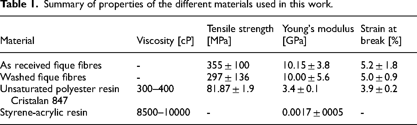
Figure 6a clearly shows that the gap in the uncoated fibres/matrix has been filled with the acrylic resin in the coated fibres (see Figure 6b). Nanoindentation results also support this finding because uncoated fibres’ composite shows a discontinuous elastic modulus-position graph and a drop just at the interphase while coated fibres’ composite has a continuous and smooth transition of the elastic modulus between fibre and matrix. On the other hand, the elastic modulus value of 17 MPa for the isolated acrylic resin, is not obtained at the interphase, this behaviour is mainly due to the size of the indentation: the diagonal of the indentation imprint left is about 1.5 µm, which represents 1/6 of the interphase thickness, a value bigger than 1/10, recommended in the literature for not to have any influence of the substrate or phases near the indentation 35 ; therefore, the contact stiffness is influenced by both the fibre and the matrix.
Pull-out test
Figure 7 shows representative interfacial shear strength-displacement pull-out curves for different composites. Three main stages are recognised: i) a linear-stage followed by a non-linear behaviour located at the left side of the red arrow, ii) maximum interfacial shear strength (red arrow), where an imminent relative displacement between the surfaces of the fibres and the matrix is produced; iii) a stage characterised by a decreasing in loading with some load drops and recovery located at the right side of the red arrow, this behaviour is attributed to the decrease in the interfacial area and the friction that was generated between the fibre and matrix. 36

Load vs. displacement curves for (a) unwashed fibre and (b) washed fibre, both uncoated and coated.
Table 2 shows the results of the interfacial shear strength obtained for the different composites. Analysis of variance – ANOVA results are also presented (Figure 7). Load vs displacement curves for a) unwashed fibre and b) washed fibre, both uncoated and coated.
Interfacial shear strength (τs) of different fibre types. N = 3 for all the levels.

Figure 8 shows Tukey pairwise comparisons used to find which one of the mean values of the different treatments was statistically different.

Confidence intervals for response variable interfacial shear strength.
The statistical analysis produced a p-value of 0.039, being this value lower than the confidence level allows us to conclude that the interfacial shear strength between different groups of fibres varied significantly. Table 2 suggests that the coated fibres have a higher interfacial shear strength than the uncoated ones and that the washing process by itself does not affect this property.
In Figure 8, the zero vertical reference line cut all the intervals except the pair Unwashed Coated Fibres and Washed Fibres and, barely includes the interval corresponding to Unwashed Coated Fibre and Unwashed Fibres. Considering that the washing procedure does not change the strength nor the elastic modulus, pull-out results clearly allow concluding that the coating increases the IFSS no matter if the fibre was washed or not.
Table 3 shows both the interfacial shear strength and the critical length obtained for different conditions of fique fibres into the same polyester resin as the matrix. The use of the coating for both unwashed and washed fibres does produce a much better load transference and consequently a lower critical length and a higher shear strength of the interphase.
Critical length of different types of fibre.

SEM analysis
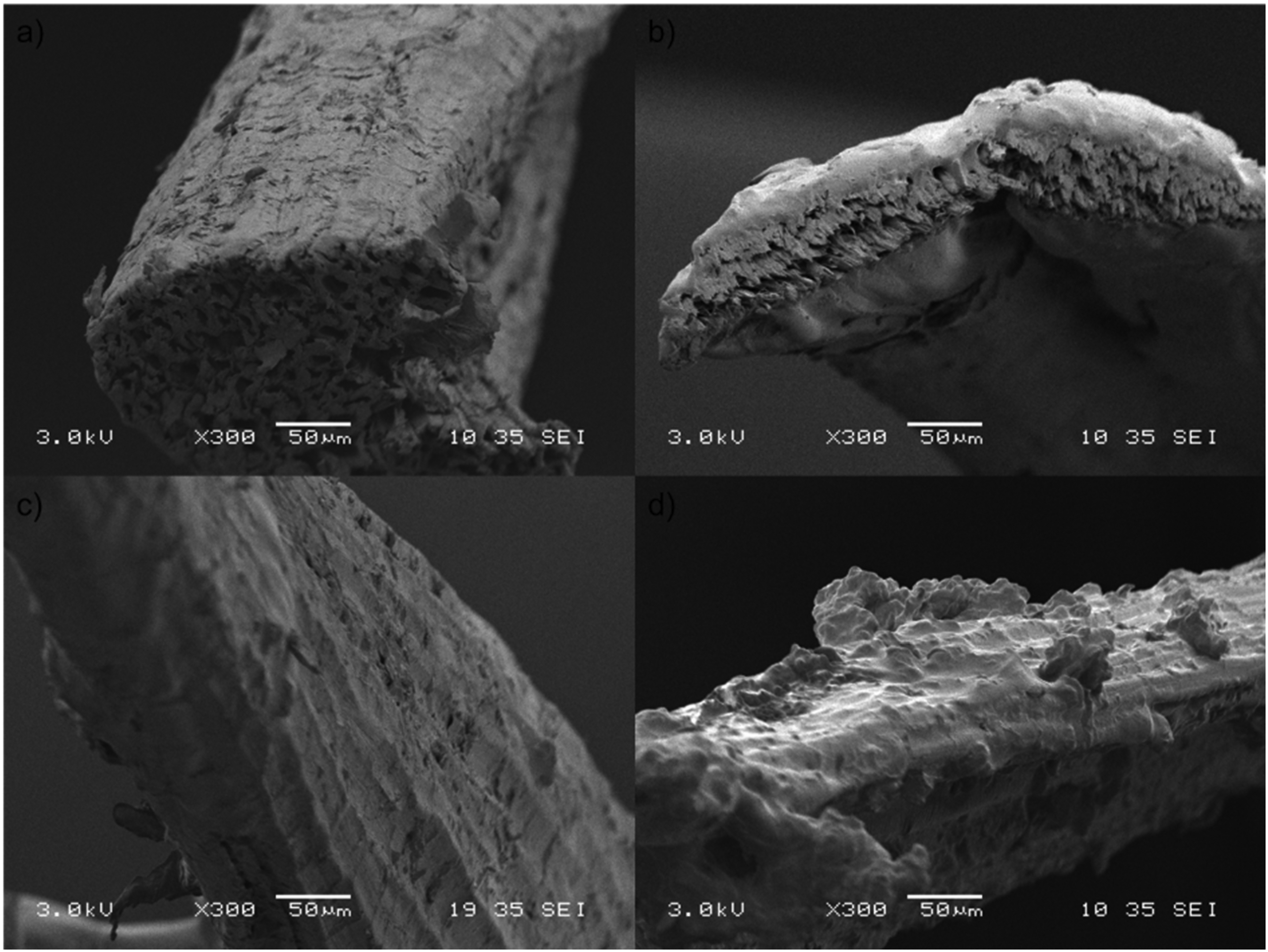
Figures 9 and 10 show the fique surface for both types of fibres, unwashed and washed, respectively; before and after pull-out tests were conducted. The uncoated fibre surface does not have any significant change induced by the washing process (see Figure 9a and Figure 10a). On the other hand, the surface of the coated fibres is smoother compared with the uncoated ones since the applied coat covers the valleys and crests (see Figure 9b and Figure 10b). The coating process produces a layer of about 10 µm in thickness 4 (see Figure 4).

Unwashed-uncoated fique fibre surface (a) before and (c) after the pull-out test. Unwashed and coated fique fibre surface (b) before and (d) after the pull-out test.
Washed-uncoated fique fibre surface (a) before and (c) after the pull-out test. Washed and coated fique fibre surface (b) before and (d) after the pull-out test.
For both pulled-out uncoated fibres, the morphology of the fique fibre seems not to show any significant change due to stresses developed at the interface during the pull-out process, which reflects a low adhesion between the matrix and the fibre. On the other hand, for both types of coated fibres, the adhesion loss was located at the matrix/coating interface; as the coating continues attached to the fibre it has been deformed due to stresses generating some bumps (see Figure 9d and Figure 10d). Therefore, it can be concluded that the coating adheres well to the fibre while improving the overall interfacial shear strength as confirmed by the pull-out tests. However, the coating has not an optimal good adhesion with the matrix, this behaviour will be explained with results from micro-Raman spectroscopy as shown below.
Micro Raman spectroscopy
Figure 11 shows the micro-Raman spectra obtained from the interfacial zones of the composite samples, for both unwashed and washed fibres. Spectra from top to bottom correspond to fibre, interface fibre – interphase, interphase, interface interphase – resin and resin.

Micro-Raman spectra obtained at the interfacial zone for the unwashed fibre (a) uncoated and (b) coated.
Bands of bulk materials spectra, that is, fique fibre,37,38 styrene-acrylic resin 25 and polyester resin, 39 match well with those reported in the literature. As was mentioned above, the coating's thickness is around 10 µm; this is 10 times higher than the interaction size of the laser spot; therefore, spectra on the coating correspond to the ‘bulk material’. Nevertheless, as Figure 12 shows, the spectra of a bulk styrene-acrylic resin cylinder, manufactured with dimensions of 2 mm diameter by 4 mm length (olive line) compared with the spectra obtained from the coated fibre into the composite (blue line), shows substantial differences in the intensity for the bands located at 3056, 1031, 1000 and 777 cm−1. The first one corresponds to C-H bonds, the next two bands correspond to β ring of C-H bond and the last one, corresponds to the symmetric stretching of C-C bond from the styrene in the styrene-acrylic resin. Is hypothesised that the liquid polyester resin activates the polymerised styrene-acrylic coating, and then the styrene from the core of the coating migrates to the edge at the interface between interphase and matrix leading to a decrease in its micro Raman bands.

Micro-Raman spectra were obtained for isolated coating (olive line) and coating into composite – interphase (blue line).
To analyse the interfaces, an edge of the fibre or the matrix was focused using optical microscopy. At the interfaces between fibre – interphase and matrix – interphase, characteristics bands of both the fibre and the matrix appear; some of them vary in intensity; however, owing to the spatial resolution of the technique, there is no evidence of any new chemical bond product of the interaction between the components.
In the case of uncoated fibres, the interphase is an ‘empty’ space or gap (see Figure 4a). In Figure 11a, the band at about 3100 cm−1 is associated with the presence of humidity. Bands found at 1460 cm−1 for the fibre corresponds to O-H bonds, while the bands found at 1724 cm−1 for the unsaturated polyester resin correspond to the C=O bonds. Therefore, with the evidence at hand, it can be concluded that hydrogen bonds are responsible for the chemical interaction between the uncoated fibres and the matrix.
On the other hand, the coating used has a polar and a nonpolar part in its chemical composition.40,41 The polar part is associated with the available carboxyl groups (C-O), evidenced by the presence of a band at 1728 cm-1, while the non-polar part is made up of the carbon chains found in the coating and the double bonds in the acrylic structures. Spectra at the interface matrix – interphase, show no new bonds and, if the total nonpolar characteristic of the polyester resin is considered, it can be concluded that probably the only chemical force that acts between the coating and the matrix is the London dispersion forces, that occur between nonpolar molecules. 42
OH groups available in the fibre, which correspond to cellulose, hemicellulose and lignin, showed a band at 1460 cm−1. These OH groups can interact with the carbonyl groups (C-O) found in the coating (band at 1728 cm−1). Although using micro-Raman spectroscopy no new bonds were detected, the contact between the two functional groups mentioned above can generate a chemical esterification reaction for which a hydronium ion (H+) and the presence of a molecule with a carbonyl and oxygen with two free electron pairs available are the requisites in order to obtain an excellent leaving group. 42
Acetic acid is a weak organic acid having partial dissociation. When the coating is mixed with acetic acid, the H+ of the solvent becomes the second hydrogen required by the carboxylic group of the coating to be able to carry out the esterification reaction; when oxygen has one pair available and three single bonds, the molecule reacts by breaking the bond with the oxygen that has the two hydrogens bonded, producing a carbocation and a water molecule, known as a leaving group. The carbocation is a highly unstable molecule and therefore reacts easily with other molecules that are nearby. Reactions explained above could happen when the fibre is coated with the coating solution, the carbocation reacts with the OH groups that are available on the fique surface, producing an intermediate state in the esterification reaction, which then reacts with the acetate ion causing a break in the hydrogen bond, producing acetic acid on the one side, and on the other the ester, 42 a bond which is much stronger than the Van Der Waals interactions that happen between the uncoated fique fibre and the matrix. This could also help to explain why in the pull-out test, the detachment of the coated fibre was produced between the matrix and the coating rather than between the fibre and the coating, as was observed in the images obtained by SEM in which no coating loss was observed due to stress at the interface matrix – interphase (see Figure 10).
The fact that hydrogen bonds are stronger than other intermolecular forces 42 should represent a greater interfacial shear strength for the uncoated fibres; however, as Figure 4a shows, there is an empty space between these fibres and the matrix, so the primary adhesion mechanism is mechanical anchoring, and the hydrogen bonds are relegated. On the other hand, the closer contact between the coating and the matrix through London dispersion forces plus the mechanical anchoring leads to better behaviour at this interface than the hydrogen bonds between uncoated fibres and the matrix.
Conclusions
The manufactured composites using coated fique fibres and polyester resin had a smooth increase in elastic modulus form the matrix (resin 4.3 GPa) to the fique reinforcement (12 GPa). Mechanical properties of the interface are affected by the materials surrounding it due to the indentation/interface relative size. The interfacial shear strength for uncoated fibres washed and unwashed were 2380 and 2570 MPa, respectively, while in the case of coated fibres, both washed and unwashed were 5003 and 5453 MPa, respectively; it represents an improvement of around 110% for coated fibres in comparison with uncoated ones. The increment interfacial shear strength had a direct influence on the critical length of the fibres, represented by a decrease of around 50% in this length; it is related to the capability to recover the load at a certain distance in a composite material after a break of the fibre. In general, uncoated fique fibres do not have good adhesion with polyester matrix due to the gap between both components, which weakens the attraction by hydrogen bonds, leading the mechanical anchoring as the primary adhesion mechanism. The styrene-acrylic coating deposited onto the fique fibre generated new interphase between fique fibres and polyester resin, promoting a better adhesion between the fibre and the matrix. The fique fibres underwent an esterification reaction with the coating; this chemical bond is strong and was evidenced when the fibres are still coated after fibre extraction in the pull-out test. Finally, the non-polar part of the coating interacted with the resin through London dispersion forces.
Footnotes
Acknowledgements
The authors acknowledge the funds provided by Royal Society of Edinburgh through SFC GCRF Escalator Fund 2019/20, and Royal Academy of Engineering – RAEeng through the Transforming Systems through Partnership programme with the project TPS1312, the Universidad Nacional de Colombia and the Instituto Tecnologico Metropolitano – ITM, both located at Medellin, Colombia. Additionally, the authors thank Compañía de Empaques for providing the fique raw materials and a special thanks to the Chemical Natalia Marin for her invaluable contributions for understanding the chemical interactions between the materials.
Declaration of conflicting interests
The author(s) declared no potential conflicts of interest with respect to the research, authorship, and/or publication of this article.
Funding
The author(s) disclosed receipt of the following financial support for the research, authorship, and/or publication of this article: This work was supported by the Royal Society of Edinburgh, Royal Academy of Engineering, Instituto Tecnológico Metropolitano, Universidad Nacional de Colombia, (grant number SFC GCRF Escalator Fund 2019/20, Transforming Systems through Partnership Programme).