
Abstract
Fatigue of composite materials is a very complex phenomenon, to date a numerous research effort is being spent on it. Because of deficiencies in study of flexural fatigue performance basalt fiber reinforced polymer (BFRP), the main objective of this work is to investigate the flexural fatigue performance of BFRP. The laminates of 4.0 mm average thickness were fabricated using the vacuum infusion technique. Three different stress levels of (162.90, 122.24, and 81.44) MPa were considered. A failure criterion was considered to be a 20% stiffness reduction of flexural fatigue test. Also, the stiffness reduction zones in the history of fatigue specimen were investigated. The failure mode of specimen at 20% reduction stiffness was inspected. The Weibull distribution function was used to obtain the failure probabilities and scatter. The S–N curve of composite laminates was constructed using five specimens at each number of cycles. This study indicated that under fatigue loading, the stiffness degradation process of composite materials was divided into three stages: the first is the high rate of stiffness degradation at the first few thousand cycles. The second stage then takes place with slow gradual stiffness degradation, which covers a sizeable portion of the component life. Finally, more grave types of damage occur, like fiber fracture, and induce complete material failure.
Keywords
Introduction
In the last two decades, fiber reinforced polymer composites (FRPCs) have been extensively used in many industrial applications, such as automobile, aerospace, military, and marine.1–6 Over the years, FRPCs have been used instead of metal materials, due to the advantages they offer in respect of mechanical properties, low cost, corrosion resistance, high strength-to-weight, and worthy fatigue resistance. 7 Composite materials also provide noteworthy freedom to the designer by permitting and optimizing the stiffness and strength of a component of structure for an application. 8
During their service life, FRPCs for most engineering applications are commonly subjected to fatigue loading. Fatigue loading can be considered as critical loading that induces the most frequent failure type in composite component. 9 The importance of studying the fatigue life of composite engineering is mostly regarding the fact that failure could take place at a stress level lower than that required to cause static failure. Several factors could affect the fatigue life, such as fiber volume fraction, material constituents, fiber orientation initial stress level, loading frequency, and environmental condition. 10
The failure of composite materials when subjected to fatigue loading is more complicated than that of metal materials. In reality, because of the anisotropic and heterogeneous nature of composite materials, different stress levels are formed under loading, so that the fracture process consists of various combinations of damage modes, such as matrix crack, fiber breakage, delamination, fiber/matrix debonding, fiber splitting, or a combination of them. 12 Furthermore, defects and voids contained in the fabricated composite can accelerate the fatigue failure of composite materials.
Due to the complicated nature of composite materials under fatigue loading, many research studies have been conducted. Selmy et al. studied two different types of glass fiber/epoxy (unidirectional glass fiber/epoxy,
Beyene et al. 15 and Beyene and Belingardi 16 investigated the flexural fatigue failure of twill fabric E-Glass/Epoxy composite. Four-point flexural fatigue test was conducted under displacement-control. They observed that the fatigue fracture of composite materials is not essentially due to either one single crack, or the first crack that enlarges. Koricho et al., 17 Abd El-baky, 18 Akhlaghi et al. 19 and Najafi et al. 20 observed that fatigue failure is most frequently regarding a reduction material stiffness, rather than specimen fracture.
No work in the literature to date has dealt with the flexural fatigue performance of plain woven basalt fiber/epoxy. The present study investigates the experimental evaluation of flexural fatigue behavior of basalt fiber reinforced polymer. The composite laminates were fabricated using the vacuum infusion technique with an average thickness of 4.0 mm. Three different initial stress levels of (162.90, 122.24, and 81.44) MPa were established. A 20% stiffness reduction of flexural fatigue test was considered as a failure criterion. Also, the stiffness reduction zones in the history of fatigue specimen were investigated. The failure mode of specimen at 20% reduction stiffness was investigated. The Weibull distribution function was used to obtain the failure probabilities and scatter.
Experimental procedure
Specimens fabrication
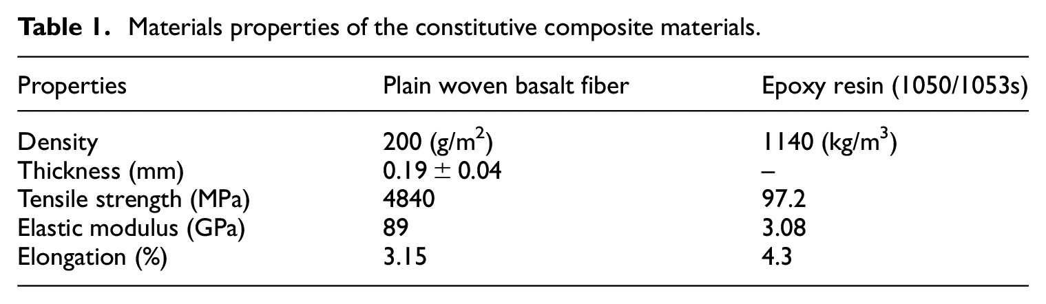
In this study, the materials under investigation are plain woven basalt fiber/epoxy. Table 1 shows the material properties of the composite laminates. Plain woven basalt fiber was supplied by Basalt Fiber Tech Pty. Ltd., Australia. Epoxy resins were obtained from Resoltech Advanced Technology Resins, Korea, and mixed with hardener ratio of 100:35 to accelerate the hardening of epoxy resin.
Materials properties of the constitutive composite materials.
To obtain more reliable and economical fabrication of the test specimen, care should be taken to select a proper mold material that can be reused. To accomplish high-grade surface specimen, a glass table was cleaned with acetone to remove all traces, such as silicone, oil, and wax. Then, the infusion layup was used to spray the surface of each lamina ply, to make sure each layer would bind to another. To evade voids and captured air inside the wet prepreg, the mold was enclosed by plastic vacuum bag as shown in Figure 1, and exposed to a vacuum pressure of 1 bar. The mold with pressure was kept for around 1 h, to ensure the pressure of 1 bar remained throughout the initial stage. The epoxy resins were allowed into the mold to soak the lamina ply. After implementation of the vacuum infusion process for 24 h, the mold was removed, and the specimen was cured in the temperature chamber for 16 h at 60°C. The manufactured FRP plates were then cut by a diamond cutter machine to the required dimensions for flexural fatigue coupon test specimens (Figure 2). The dimensions of the fatigue specimen followed the previous research, but the middle section of the specimen was modified from fillet edge to chamfer edge, as shown in Figure 2. This was due to the difficulty of making the fillet edge in the current fabricating process. However, the results of specimen configuration with curve are not much different from those of specimen configuration with line.
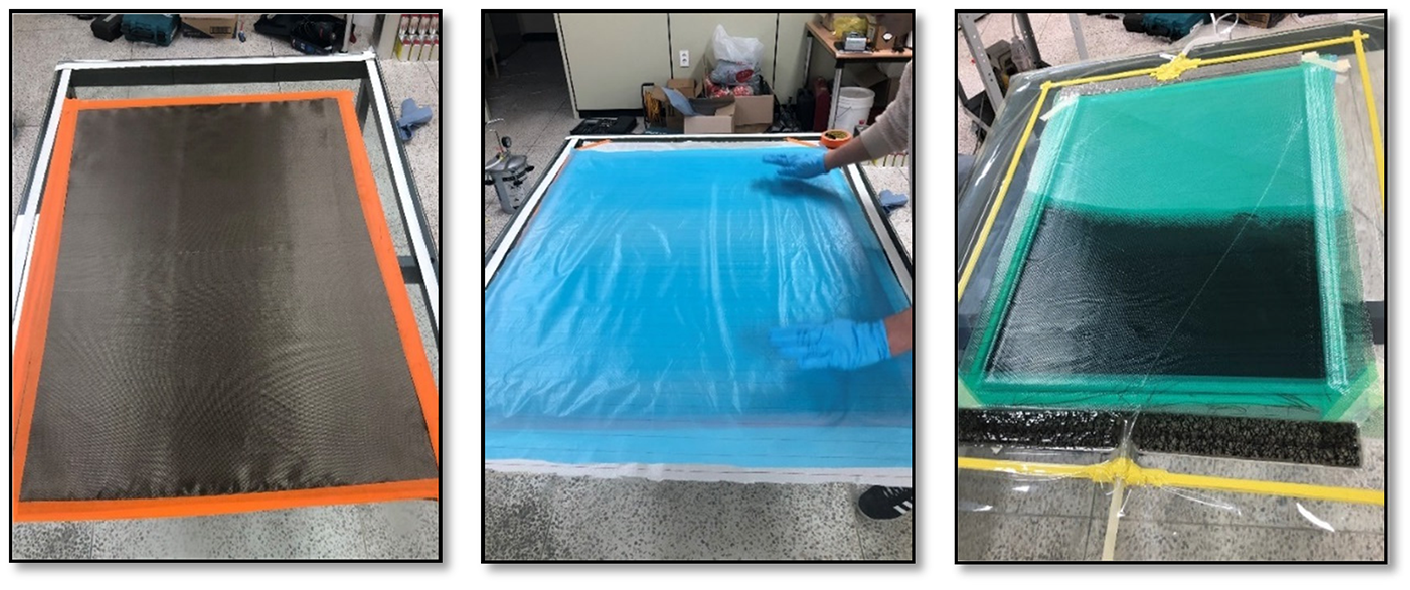
The vacuum infusion process.

Dimension of the flexural fatigue specimens.
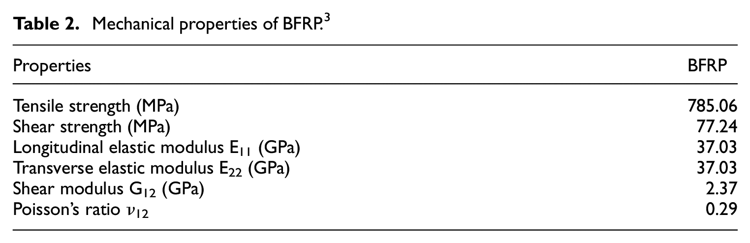
To conduct the flexural fatigue test, the required basic mechanical properties of BFRP were also provided in Table 2. Three types of initial stress level have performed in this study. Fifteen specimens have been experimentally conducted under the flexural fatigue test; five samples for each initial stress level have been used.
Mechanical properties of BFRP. 3
Test procedure
The machine shown in Figure 3 is designed to apply an inverse bending stress. The machine specifications are 5 mm maximum displacement, and 1200 cycles per minute. Steel plates provided pressure for the fixation of specimens, as shown in Figure 4. An eccentric was used to change the applied displacement on the specimen. Figure 3(a) shows a front view of the flexural fatigue testing machine demonstrating all the required details, whilst Figure 3(b) shows the back of the testing machine, revealing the frequency counting sensor and the eccentric. The oscillating displacement is imposed at the free end of the bending fatigue specimen by a reciprocating spindle. In the present investigation, flexural fatigue tests were run at a frequency of 10 Hz with the cyclic stress ratio R of 1. The load is captured by load cell near the test specimen, and then data is transferred to computer by data logger. To measure the strain, the strain gauge is attached at the center of the specimen.
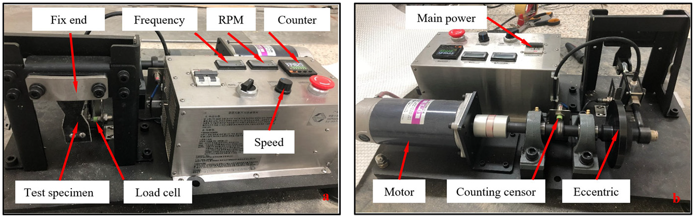
Flexural fatigue machine: (a) in front view and (b) back view.
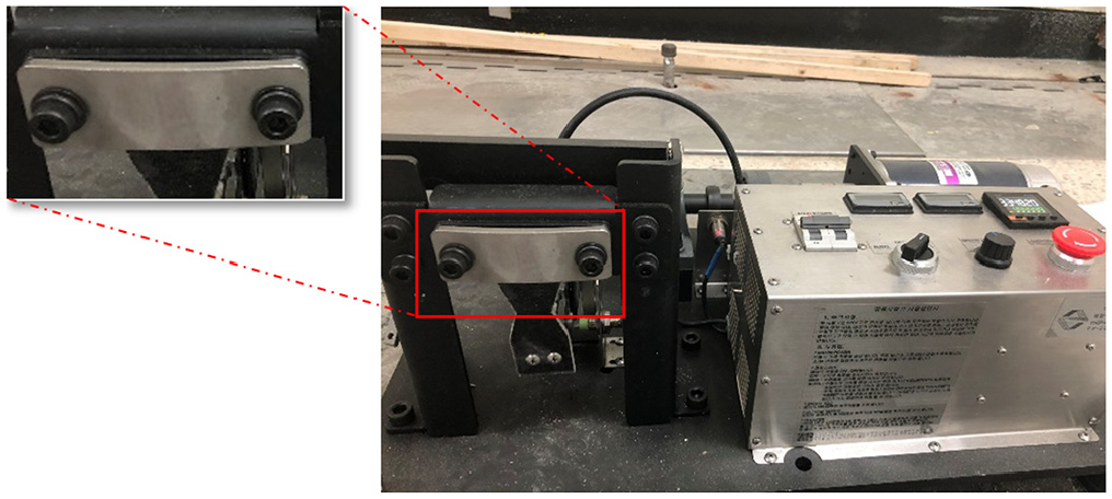
Fix point in the present flexural fatigue machine.
Residual stiffness degradation of flexural fatigue test specimens
To capture and measure the residual stiffness ratio

where,


Machine scheme of the flexural fatigue test.
The bending moment after an exact number of cycles is:

where,


where,
Statistical analysis of fatigue-life data
The two-parameter Weibull distribution function is frequently used to assess product reliability, and analyze fatigue-life data and model failure times. It is characterized by the associated cumulative distribution function


where,
Analysis of fatigue-life data by the graphical method
The reliability function

By applying the logarithm on both sides of equation (8), equation (9) is obtained:

Based on equation (9), it can be seen that the relationship between
In order to derive a graph from equation (9), the numbers of failure cycles

where,
Failure probability Pf and S–N relationships
The two-parameter Weibull distribution function is used to integrate failure probability into the S–N curve for the manufactured composite laminates. Then replacing

To obtain value

To get the fatigue lives
Scatter of fatigue life data
Mean time to failure (MTF), standard deviation (SD), and coefficient of variation (C.V.) of two-parameter Weibull distribution were determined from the following equations 23 :


Results and discussion
Failure modes
The flexural failure modes of plain woven basalt fiber/epoxy composite specimen that were used in this study were examined at 20% reduction stiffness. The recorded behavior and discussion are illustrated in the following:
When basalt fiber/epoxy was subjected to high stress amplitude (
Under medium stress amplitude (
At low stress level (
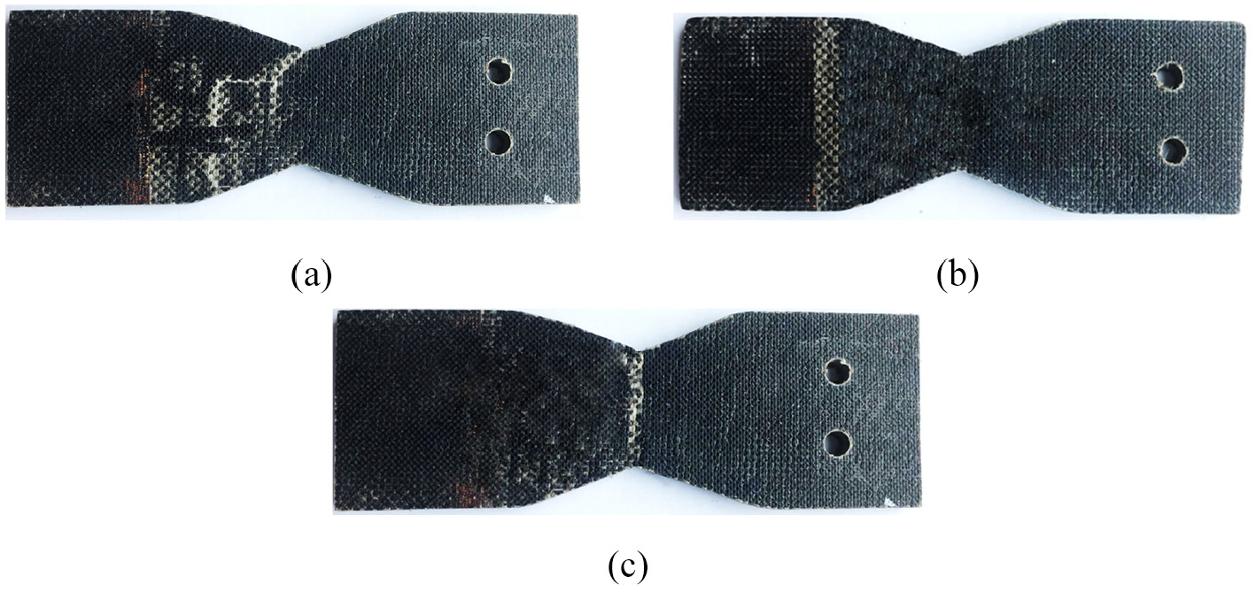
Failure mode of BFRP fatigue specimen: (a) a fracture near the specimen middle, (b) a visible fracture near the fixed end, and (c) surface fracture specimen near middle.
Stiffness reduction zone in the specimen fatigue history
In general, when composite materials are subjected to cyclic loading, intra-laminar and inter-laminar damage starts and progressively accumulates, according to the different types of stress arising from the anisotropic and heterogeneous nature of the fiber reinforced composite (FRC), and the levels of stress arising from the geometric or material discontinuities around the edges. This accumulation and propagation of crack eventually results in the loss or degradation of the mechanical properties, such as strength and modulus. 15
Figure 7 illustrates a representative curve to describe how the stiffness progressively reduces with the number of cycles. This completed fracture curve was obtained from the specimen under stress level of 122.24 MPa. Complete material failure occurs when the material reduces stiffness by around 55% of its original stiffness. Actually, the percentage decrease of stiffness at failure is not constant, but is a resultant of the applied loading level, applied frequency, and type of material. For the materials used, at the low load level, it can be seen that complete fracture can also take place after the reduction of the bending stiffness is greater than 70% of its initial stiffness. Whereas, with high stress level, the whole fracture happens, even at reduction stiffness less than 20% of the preliminary stiffness. As several researchers have observed, when a composite component is subjected to flexural fatigue loading, there are three different stages in the degradation of stiffness.15,24,25 As can be seen in Figure 7, there is high rate of stiffness degradation at the first few thousand cycles (stage I). Then the second stage take place with slow gradual stiffness degradation, which covers a sizeable portion of the component life (stage II). Finally, more grave types of damage, like fiber fracture, occur, and induce complete material failure (stage III).

Three distinct stiffness reduction zones in the history of fatigue specimen.
Relationship between residual stiffness and number of cycles in fatigue test
Figure 8 shows the variation of the experimental results and predicted value of the residual stiffness ratio

S–N curve BFRP composite laminates.
Figure 9 shows the relationship between residual stiffness ratio and cycles ratio

Variation of residual stiffness ratio
After the preliminary reduction in stiffness, gradual linear reduction in the residual stiffness ratio was detected down to 80% of the initial stiffness of the test specimens. This slower stiffness reduction may be because of the cracking of matrix in the test specimens, so that the applied load needed to sustain a constant strain becomes minimal. Because of the slow decrease rate of the crack propagation, the reduction stiffness takes a long time to reach the residual stiffness ratio of 80 %. This result is in agreement with previous research.
26
According to this figure, it can be noted that the association between residual stiffness ratio
Statistical analysis of fatigue life data
Figure 10 shows the graphical analysis of the fatigue life data of BFRP composite laminate. The shape parameter

Graphical analysis of fatigue life data of BFRP composite laminates.
Equation (12) was utilized to determine the fatigue lives at a given stress level coordinated with different failure probabilities. Table 3 lists the two values of the Weibull distribution parameters used in equation (12) for any stress level. Figure 11 plots these calculated values of fatigue life of the tested samples for failure probabilities of Pf = (0.3, 0.5, 0.7, 0.9, and 0.95). The equations in this figure can be used to predict the fatigue life of BFRP composite at another stress level for each failure probability.
Statistical analysis of the fatigue life data.


Probability S–N diagram of the BFRP composite laminates.
Figure 12 shows the variation of the coefficient of variation (C.V.) versus mean time to failure (MTTF) at different stress level. Standard deviation (SD), mean time to failure, and coefficient of variation for fatigue life of BFRP composite can be obtained by using equations (13)– (15). On the report of this figure, it can be noted that this variation has no identify. It can also be seen that the maximum value of (C.V.) is observed at the number of cycles of 44,200 (initial stress 122.24 MPa), while the minimum value is observed at the number of cycles of 546,000 (initial stress 81.44 MPa). This is due to lower applied initial stress level that cause the performance of specimen reach to reach failure gradually and consistently, compare to that of higher initial stress level. This trend is exceedingly significant for the application and design of BFRP structure.

Relationship between MTTF and C.V.
Conclusions
The flexural fatigue performance of plain woven basalt fiber/epoxy was investigated. Flexural fatigue tests were conducted at a frequency of 10 Hz with the cyclic stress ratio R of 1. A 20% stiffness reduction of flexural fatigue test was considered as a failure criterion. Also, the stiffness reduction zones in the history of fatigue specimen were examined. The fractured specimen at 20% reduction stiffness was investigated. The experimental results can be summarized as follow:
It can be noted that under the fatigue loading, the results of BFRP composite materials could be divided into three stages of the stiffness degradation process: for the first few thousand cycles, there is high rate of stiffness degradation. The second stage, which covers a sizeable portion of the component life, then takes place, with slow and gradual stiffness degradation. Finally, more grave types of damages, like fiber fracture, occur, and induce complete material failure.
Under fatigue loading, the initial stress level has a significant effect on the failure mode of the specimens. Under high stress level, visible cracks were observed near the middle of specimen. Meanwhile under medium stress level, cracks appeared at the fixed end. For low stress level, cracks were visible at the middle of specimen.
Using Weibull distribution, failure probability curves at different stress level were obtained for BFRP composite in this study. In design, these curves are useful for structural engineers to determine the fatigue life of the BFRP composite materials.
The maximum value of coefficient of variation was obtained at the number of cycles 44200 for initial stress level of 122.24 MPa, and the minimum value at cycle 546000 for initial stress level of 81.22 MPa. This may be attributed to lower applied initial stress level that cause the performance of specimen to reach failure gradually and consistently, compare to that of higher initial stress level.
Based on the S–N curve, it can be seen that the correlation coefficient R2 between the initial applied stress
In future study, the flexural fatigue machine will be developed with an automatic limited force-controlled function to facilitate the testing procedure. Another improvement to avoid stress concentrated at the edge of hole, as well as slippage of the specimen during test processing, would be to combine both types of fixed point: bolt and pressure from steel plate, for the specimen for flexural fatigue test, as illustrated in Figures 13 and 14, respectively.

Applied bolts as a boundary condition.
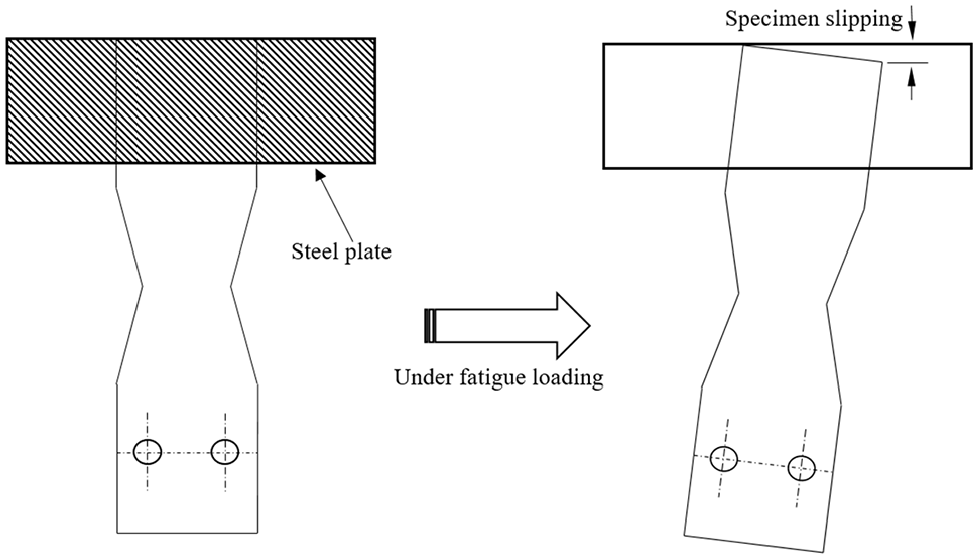
Applied steel plate as a pressure boundary condition.
Footnotes
Acknowledgements
This present work is supported by a National Research Foundation [NRF] grant, funded by the Korea government [MEST][No.2017R1A2B3008623] and by the Korea Agency for Infrastructure Technology Advancement(KAIA) grant, funded by the Ministry of Land, Infrastructure and Transport (Grant 21CFRP-C163381-01).
Declaration of conflicting interests
The author(s) declared no potential conflicts of interest with respect to the research, authorship, and/or publication of this article.
Funding
The author(s) disclosed receipt of the following financial support for the research, authorship, and/or publication of this article: This present work was supported by a National Research Foundation [NRF] grant, funded by the Korea government [MEST] [No.2017R1A2B3008623].