
Abstract
To improve the output flow characteristics of the piezoelectric pump in one direction, a new valveless piezoelectric pump with a crescent dune bluff body has been proposed. The pump can achieve low damage to the active substance on the premise that the active cell can guarantee the transport volume. By comparing with the hemispherically deficient and imitated meniscus resistance fluid, the barchan dune resistance fluid which can effectively improve the unidirectional output of the piezoelectric pump is obtained. Combined with the pump theoretical flow calculation formula, these influencing parameters, the degree of inclination, the sand ridge radius and the order of the crescent dune were analyzed. Finally, an experimental prototype of a valveless piezoelectric pump has been fabricated by 3D printing technology, and the pump flow test is being conducted. The relationship between frequency, voltage and output flow has been obtained. The test results show that with a dune inclination of 37.5, a sand ridge radius of 6.75 mm and a dune order of 4, the flow rate of the piezoelectric pump is best at 194.7 mL/min. The experimental results agree with the simulation results, showing the effectiveness of the valveless piezoelectric pump structure.
Introduction
Valveless piezoelectric pumps have the advantages of resisting interference, simple structure, low power consumption, and are used in medical and health fields. Since there is no moving spool, a flow formation is realized by bluff bodies with different flow properties in different directions, which has a small influence on the activity of the transferred substance. Therefore, the valveless piezoelectric pump has a wider application in transferring and mixing the active substance.1–3
The valveless pump has three types, namely external flow tube type, built in structure type and bionic type. The type of external flow tube mainly depends on the shape of the flow tube to change the flow resistance, such as: B. Cone, Y type and Tesla valve type.4–6 The built in structure is designed to change the flow resistance by the internal resistance of the liquid, from the original semi-cylindrical type, hemispherical missing type, asymmetric tilt, triangular prism type to a variety of new structure combinations.7,8 The bionic type has an imitation fishtail type and built-in compliant structure.9–11
Regardless of the structural form, the primary concern is how to maximize the positive and negative flow difference. In this article, through the simulation and comparison of the previous hemispherical and imitations of meniscus resistance fluids, it is found that the forward and backward flow resistance difference of the two fluids is small, and the output capacity of one-way flow is not enough. As we all know, the streamlined structure has great advantages in reducing drag. When the bluff body having a streamlined structure is used in the incoming flow direction and the blocked flow type structure is used in the reverse direction, the flow performance can be greatly improved. 12
Inspired by the shape of desert sand dunes, a valveless crescent-shaped dune piezoelectric pump structure was proposed in this article. The pump flow equation was established by analyzing the working principle of the pump and the liquid resistance structure of the sand dune, the influence of the degree of inclination, sand ridge radius and order on the pump outlet flow characteristics is also studied. Specifically, the working principle, the structure and the theoretical process of the piezoelectric pump are analyzed in the first part. In the second part, the associated properties of the pump are analyzed and the meaningful structural parameters are examined. In the third part, a new type of piezoelectric pump is manufactured and corresponding experiments are carried out. Finally, the conclusion is drawn.
Shape, structure and discharge of dune
Shape of dune
Crescent dunes are formed by unidirectional wind erosion, their superior level is like a crescent shape. Its appearance is characterized by two sharp angles formed at the end of the dune along the downwind direction of the incoming flow. Its windward inclination increases relatively gently, with a convex surface and a small inclination, generally between 5 and 20. When the forward wind blows past, the resistance is relatively small. However, the leeward slope is relatively steep and concave with an inclination of 28 to 34. When the headwind blows, the resistance is relatively large, and air vortices are easy to form on the concave surface.
In this work, the crescent-shaped dune on the southeastern edge of the Taklimakan Desert is selected as a research object and modified. Its structure is shown in Figure 1.
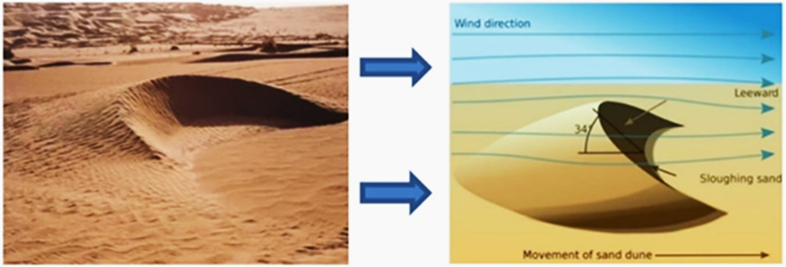
Contour of crescent dune.
Fluid resistance and pump structure
The flow obstacle structure of the crescent-shaped dune is shown in Figure 2, and the height is h = 1.5 mm, the width is L = 10 mm, other parameters are L1 = 2 mm, L2 = 5 mm.
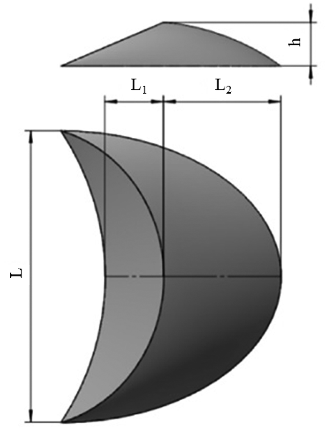
3D model of bluff body of crescent dunes.
The mechanical structure of the valveless piezoelectric pump is shown in Figure 3. It consists of barrier fluid, sealing ring, piezoelectric vibrator, chamber and end cap. The piezoelectric vibrator vibrates up and down to control the fluid entering and exiting the chamber. The barrier fluid reduces the pressure loss of the liquid flowing forward into the pump chamber and increases the pressure loss of the liquid flowing backward into the pump chamber, so that the positive and negative liquid forms the pressure difference, and then realizes the one-way flow of the liquid.

Schematic diagram of valveless pump.
Flow analysis
The piezoelectric vibrator is a circular piezoelectric single crystal as shown in Figure 4. In order to obtain the position information of the piezoelectric vibrator over time, the theoretical investigation of the volume change of the pump chamber can be performed.

Vibration simulation of piezoelectric vibrator.
The center of the piezoelectric vibrator is taken as the coordinate origin and analyzed in the polar coordinate system. R is the radius of the oscillator, ω is the curvature of the oscillator, then the average flow velocity of the fluid in the positive and opposite directions in the differential tube of flow resistance can be expressed by Equations (1) and (2):


During a half cycle of movement of the piezoelectric vibrator, which raises the process and returns to the equilibrium position, fluid is dispensed simultaneously from both ends of the catheter. The formula of the flow rate Q is:


Simulation analysis
Methods and conditions
Piezoelectric pump simulation methods are generally divided into two types, the first type for import and export exchange simulation, forward flow, the inlet sets a certain pressure, the outlet for the open limit, reverse flow, the outlet sets a certain pressure, the inlet for the open border. The drag properties of the decelerated fluid were verified by the forward and reverse velocities of the simulation results. The second is to take two flow tubes as the inlet at the same time to simulate the actual water suction stage of the pump. In reverse drainage, the lower chamber of the piezoelectric vibrator is used as the inlet in the normal support state, and two flow tubes are used as the outlet at the same time to simulate the actual drainage stage of the pump.
Because the vibration frequency of the piezoelectric pump vibrator is relatively fast, the adjustment of two flow tubes in the outlet state does not match the actual pump chamber. Therefore, in this document, the first simulation analysis method is applied, i.e. H. in the forward flow, the pressure at the inlet is set at 1600 Pa, and the outlet boundary condition is set as an open boundary. The liquid flows from the inlet into the pump chamber and from the outlet with reflux out of the pump chamber. In the reverse flow simulation, the pressure at the outlet is set at 1600 Pa and the inlet is an open boundary. The flow condition is opposite to that in the forward flow. The liquid medium is water and the form of flow is laminar flow.
Model verification
To verify the correctness of the model and the correlation analysis method, three different simulation models of structures are created. The first model is the traditional hemispherical structure. The second type is meniscus; The third is a crescent-shaped dune. The positive and negative flow simulation results of the above three structures are shown in Figures 5 to 7.

Flow field diagram of hemispherical bluff body.
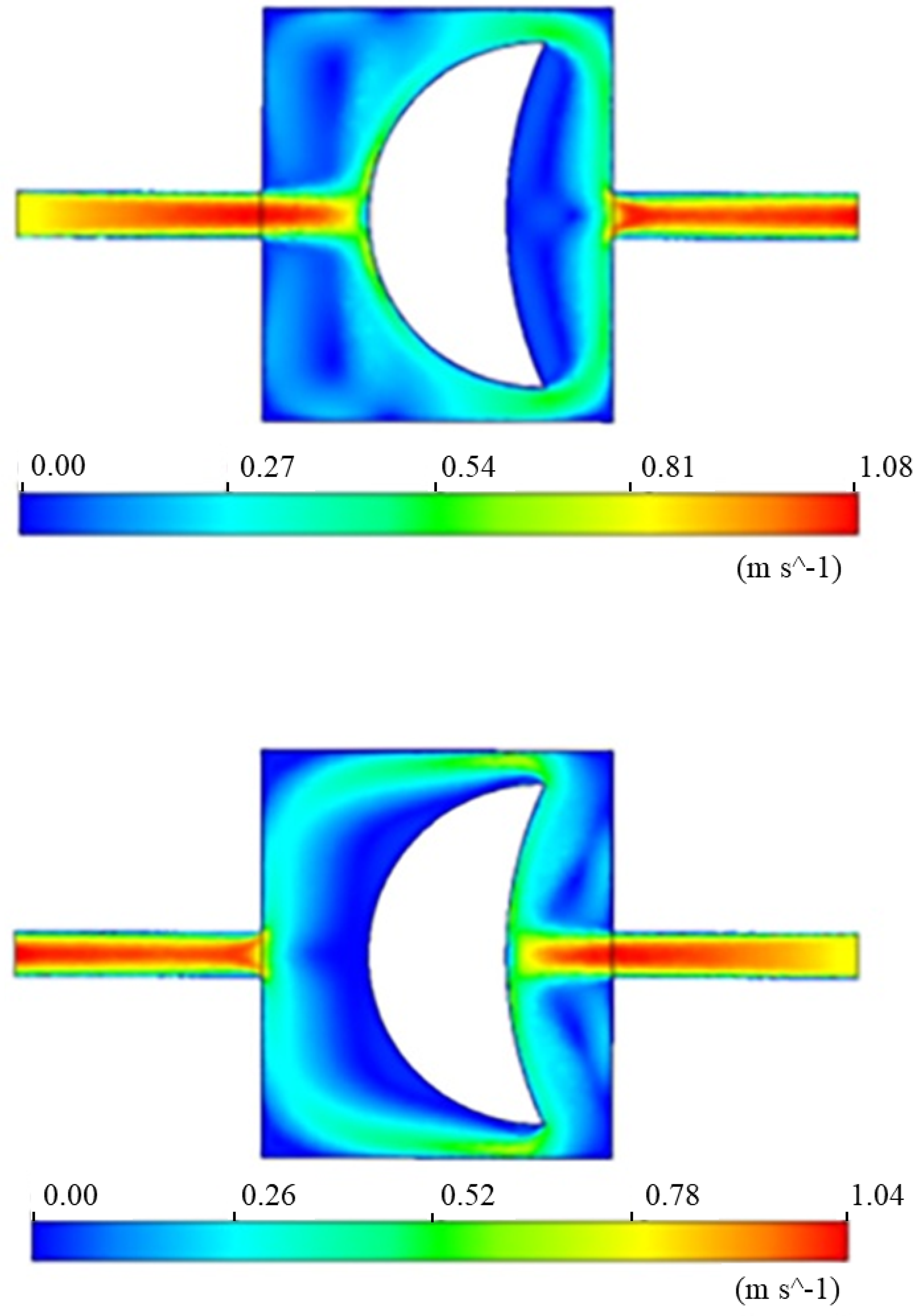
Flow field diagram of meniscus bluff body.

Diagram of the resistance flow field of the crescent dune of bluff body.
As can be seen from the simulation results of the forward and backward flow rates of the above three structures, the asymmetrically impeded fluids of the three structural forms create different obstacles to the fluid at the same pressure difference in the forward and backward directions, resulting in changes in the flow field velocity and the unidirectional flow at the macro level.
Figure 8 is a comparison of the positive and negative maximum flow rates of the three structures. Because the crescent dune structure has a gentle windward slope, the forward flow resistance of the fluid is reduced and the maximum forward flow speed is 1.108 m/s. However, the windward slope of hemispherical and imitated meniscus fluid is steeper, which hinders the forward flow velocity. In reverse flow, the crescent dune structure lee slope is steeper than the other two structures, resulting in a lower exit velocity than the first two structures. The forward and backward speed difference of the liquid-blocking structure of the crescent-shaped dune is 0.073 m/s, which is larger than those of the hemispherical structure and the imitation meniscus structure. The simulation results agree well with the relevant experience, which shows the correctness of the model and the method. The unique structure of the barchan dune with a gentle windward slope and steep leeward slope is fully utilized.

Curve of maximum forward and reverse flow rates of bluff body.
Parameter optimization
To improve the output of the piezoelectric pump, the structural tilt angle, ridge radius and dune order of the crescent-shaped dune were optimized, from which the optimal combination of parameters was found. The structural parameters are shown in Figure 9. The simulation process and parameter settings are the same as in the section “Shape of dune.”

Parameters of bluff body.
Dip angle
According to the actual downwind slope area of the dune, simulation analysis was performed for slope angles of 30°, 32.5°, 35°, 37.5° and 40°, respectively, and the forward and backward flow velocity vector diagrams of the liquid were obtained and the results were shown in Figures 10 and 11.

Forward and reverse flow velocity under different angles.

The curve of maximum forward and reverse flow rates at different angles.
It can be seen from the forward outlet velocity curve that as the tilt angle increases, the length of the delay fluid increases and the obstruction of the fluid increases. The exit velocity will first increase, then decrease and then increase. At 37.5°, the maximum forward speed is the minimum, which is due to the exit speed decreasing due to the larger vortex created at the angle of 37.5°. According to the reverse simulation outlet speed curve, the outlet speed of 37.5° at the same inlet pressure is at least 0.9802 m/s, which is due to the liquid impact on the throttle surface of the lee slope causing larger obstacles than other slump angles. When the tilt angle is 37.5°, the flow speed difference reaches 0.0978 m/s, and the flow performance is best.
Radius of ridge
The rib radius of 6.00 mm, 6.25 mm, 6.50 mm, 6.75 mm and 7.00 mm were chosen for the simulation, respectively. Figures 12 and 13 respectively show the forward and reverse flow velocity graphs and the maximum flow velocity graphs under different ridge radii. As can be seen from the forward flow rate diagram, after the fluid enters the pump chamber from the inlet, it will encounter the windward slope. A small part of the shunt creates a small vortex, resulting in energy loss. Most of the fluid flows along the windward slope to the outlet. On the leeward side of the reverse fluid impingement, there are vortices that cause fluid energy to be lost. When the radius of the ridge is 6.75 mm, the speed difference reaches the maximum of 0.119 m/s. Therefore, when the fin radius is 6.75 mm, the flow performance is best.

Velocity of forward and reverse flow velocity under different ridge radius.

The curve of maximum forward and reverse flow rates at different ridge radius.
Dune order
The positive and negative flow field simulation diagram and the maximum velocity curve diagram of the dune fluid structure 2 to 5. order are shown in Figures 14 and 15, respectively. The forward simulation plot shows that when the fluid from the inlet impinges on the multi-order structure, a symmetrical vortex is created in the first two stages to create a flow loss. The reverse fluid simulation shows that the fluid impinges on the first decelerated fluid to create a dense vortex in which a large amount of flow is lost. When the dune order is 4, the flow velocity difference is largest, reaching 0.1291 m/s. Considering that the increase in dune order affects the size of the piezoelectric micropump, the fourth-order resistance fluid structure is selected as the final design structure of the resistance fluid in the pump chamber.
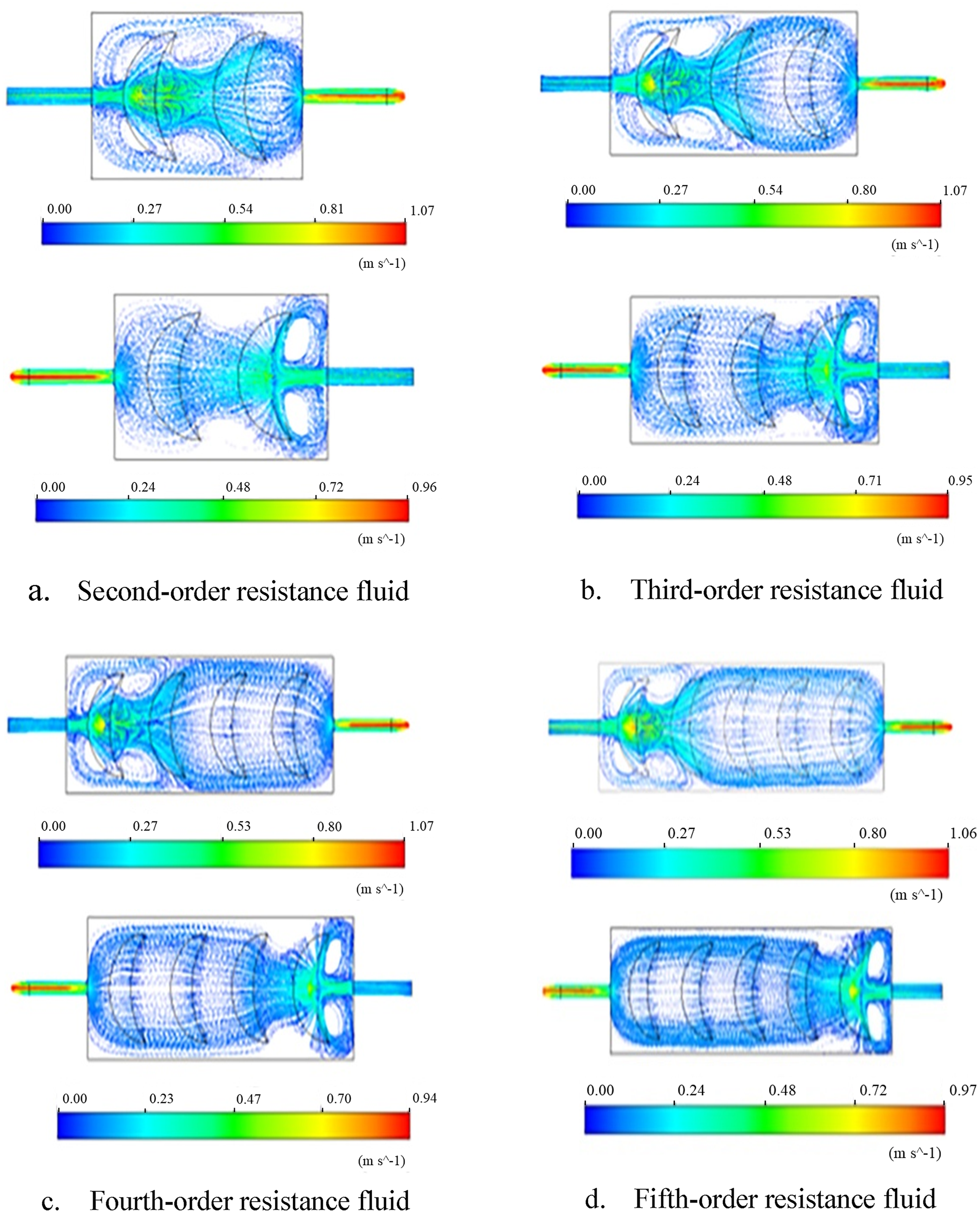
Flow field of forward and backward of different number.

Maximum forward and reverse flow rates with different structural orders.
Pump system and experimental study
The above theoretical and simulation analysis shows that the flow resistance difference will be generated when the fluid passes through the piezoelectric pump designed in this article. In this article, PLA material is selected to make the pump body. PLA is a kind of biosuperior material with degradability. The barcrescent dune valveless piezoelectric pump was designed through 3D modeling and processed with the 3D printer in Figure 16.
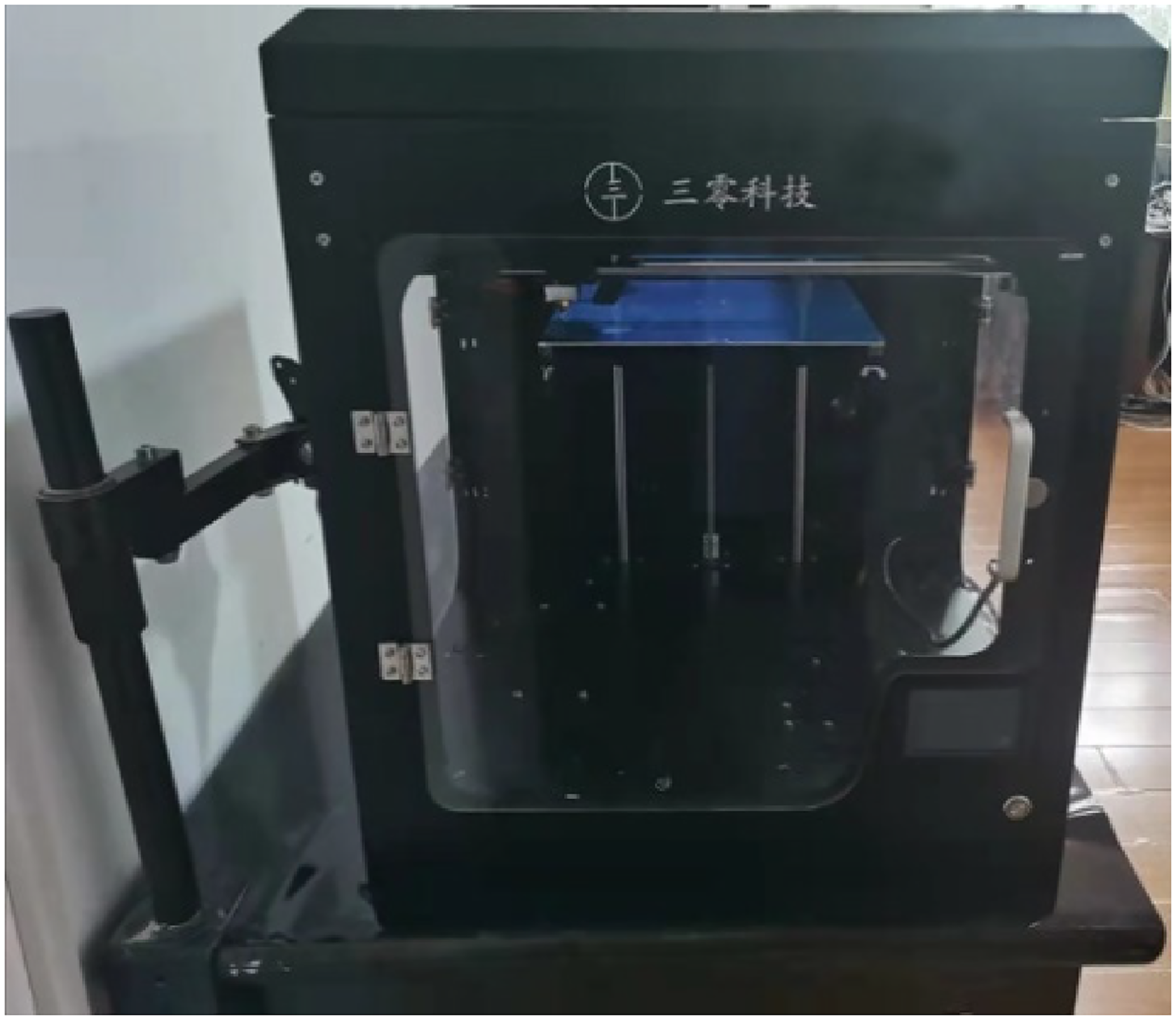
3D printer.
The test sample pump printed by the 3D printer is shown in Figure 17. The prototype manufactured by the 3D printer fully meets the requirements of the experiment in terms of manufacturing accuracy and roughness, so there is no need for further grinding and polishing on the surface of the pump.
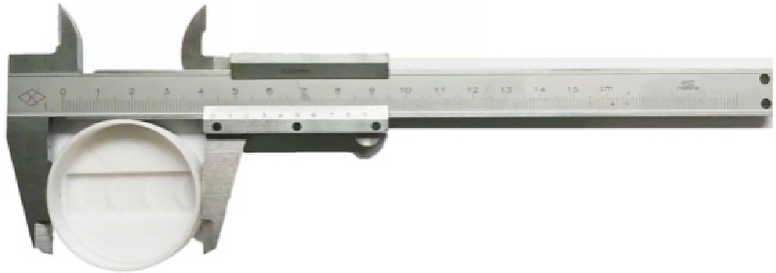
Four-stage test pump.
The flow performance test platform schematic diagram mainly includes a signal generator, power amplifier, high-precision electronic balance, sample pump, beaker, etc., as shown in Figure 18.

Schematic diagram of test.
To analyze the flow resistance and power output of the electro-hydraulic pump, the pump body, pump cover and other parts were 3D printed with PLA material, and the oscilloscope, pump flow and flow test experimental platform were built. The test platform is shown in Figure 19.
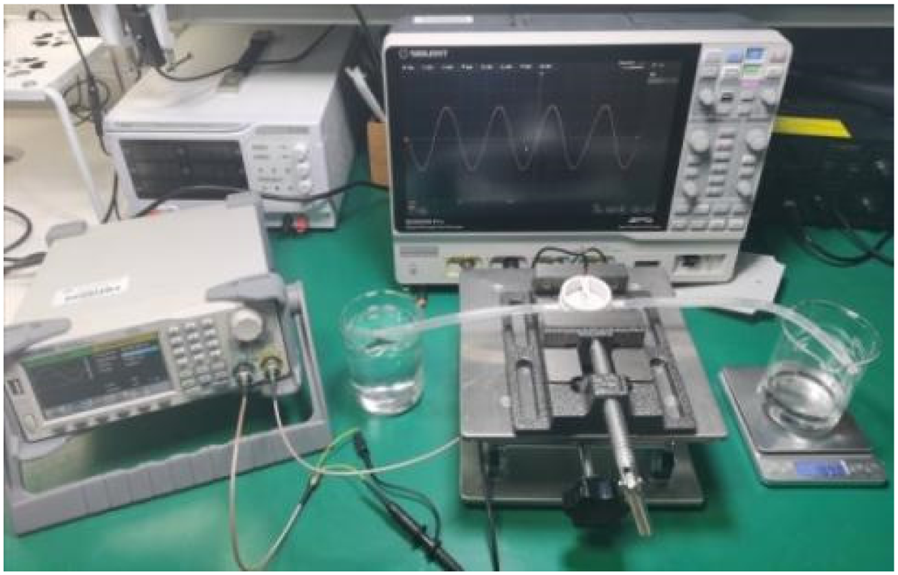
Test platform.
It is proved by theory and simulation that fluid will produce different flow resistance differences in the pump chamber of barchan dune. The above inference can be verified by experiments. However, because the flow resistance difference is not easy to measure directly, according to the characteristics of the barchan sand dune, the effect is that the flow rate through the outlet is different in the specified time. Therefore, the flow rate of the outflow pipe liquid within a quantitative time can be verified with the same pressure difference.
Influence of dune dip angle on output flow
The results of varying the output flux with frequency and voltage among five groups with different dune inclination angles were tested. Through the experiment, it was found that the output current of the pump changes steadily with the change in frequency, has a relatively linear frequency characteristic as a whole, it is easy to realize accurate control of the output current, and the piezoelectric pump has good low-frequency output characteristics. The specific test results are shown in Figure 20.
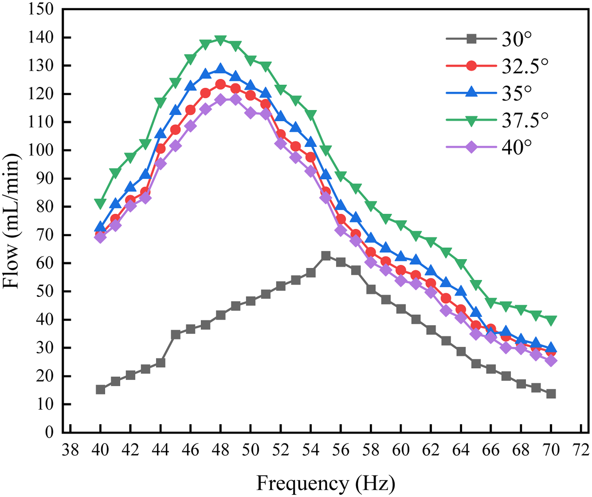
Frequency-flow curves of the prototype at different angles.
The output flow from prototypes with different dune inclination angles all showed a parabolic trend of first increasing and then decreasing frequency change, as shown in Figure 21. The prototypes with different tilt angles all had the optimum output frequency point between 48 Hz and 56 Hz. The prototype with the tilt angle of 37.5° had the maximum output flow, reaching 141.0 mL/min, which was essentially in agreement with the simulation results, and the optimal drive frequency was 48 Hz.
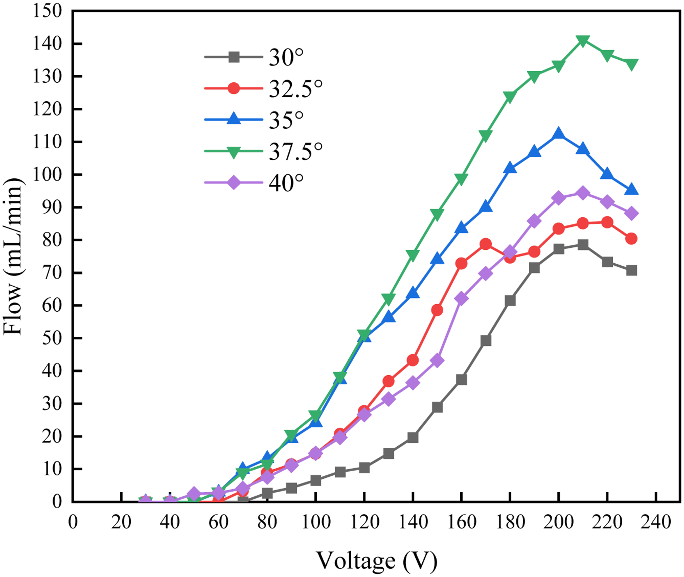
Voltage-flow curves of the prototype at different angles.
With the gradual increase in voltage, the output flow of the piezoelectric pump shows a gradual increase phenomenon, after the output power reaches the maximum value, it begins to decrease, the output flow reaches its maximum at a voltage of 210 V.
Influence of ridge radius on output flow
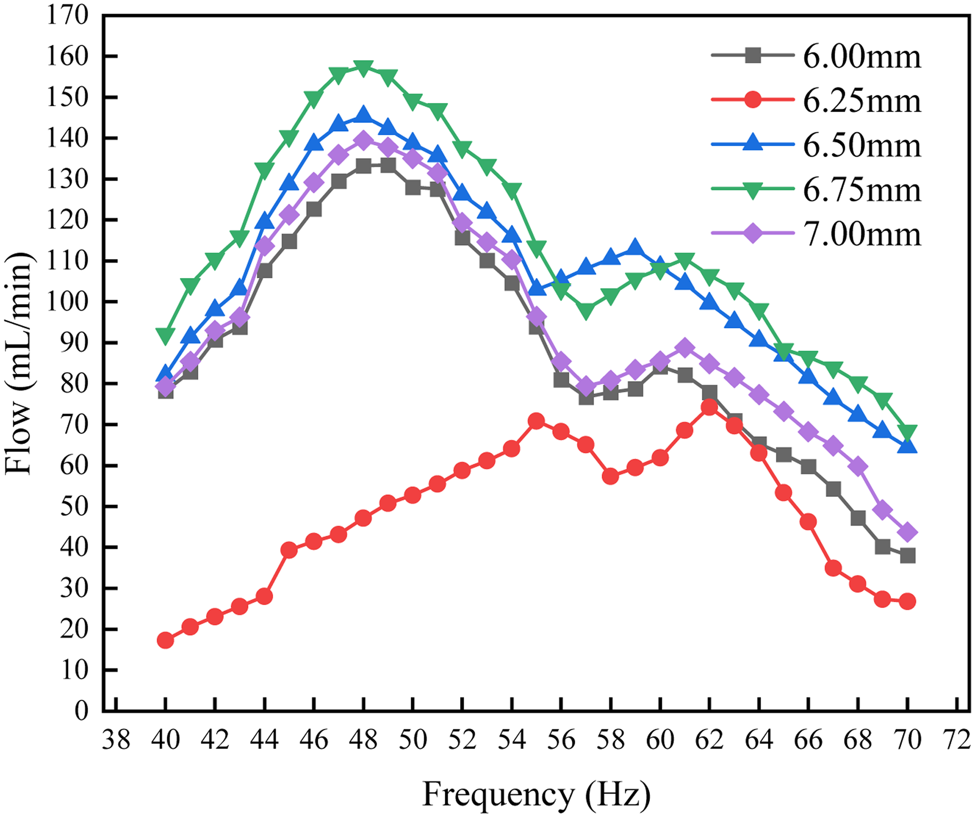
Figure 22 shows the frequency-flux curves of samples with different ridge radii. The test was conducted by controlling a single variable when the pump tilt angle was 37.5°. As can be seen from the figure, the performance of the piezoelectric pump is best when the sand rib radius is 6.75 mm. The main reason is that the flow channels on both sides of the model with this radius are relatively wide, which increases the inlet flow of the piezoelectric pump and creates a better backflow resistance compared to models with other sizes.
Frequency-flow curves of samples with different ridge radii.
The volt-flux curves of prototypes with different degrees of sanding are shown in Figure 23. It can be seen from the figure that the output power of the piezoelectric pump increases as the voltage increases. During the growth process, there are two current peaks at a voltage of 170 V, but the current peak is lower than the second peak at about 210 V. As the voltage increases, the displacement of the piezoelectric vibrator gradually increases, and the output flux increases steadily with the voltage. After the peak of the first wave, the voltage continues to increase, and a slight resonance phenomenon occurs with the pump chamber, weakening the output capacity of the flow. Then, with the continued increase in voltage, the phenomenon disappears and the maximum flux of the second wave peak appears at 210 V. From the figure it can be seen that the optimal output flux is obtained when the radius of the sand rib is 6.75 mm and the output voltage is 210 V amounts to.

Voltage-flow curves of samples with different ridge radii.
Influence of dune order on output discharge
The output power of 5 groups of different orders was tested to investigate the relationship between the output power of different structural orders and voltage and frequency. The frequency-flux curves of various dune order prototypes are shown in Figure 24.

Frequency-flow curves of prototypes with different dune orders.
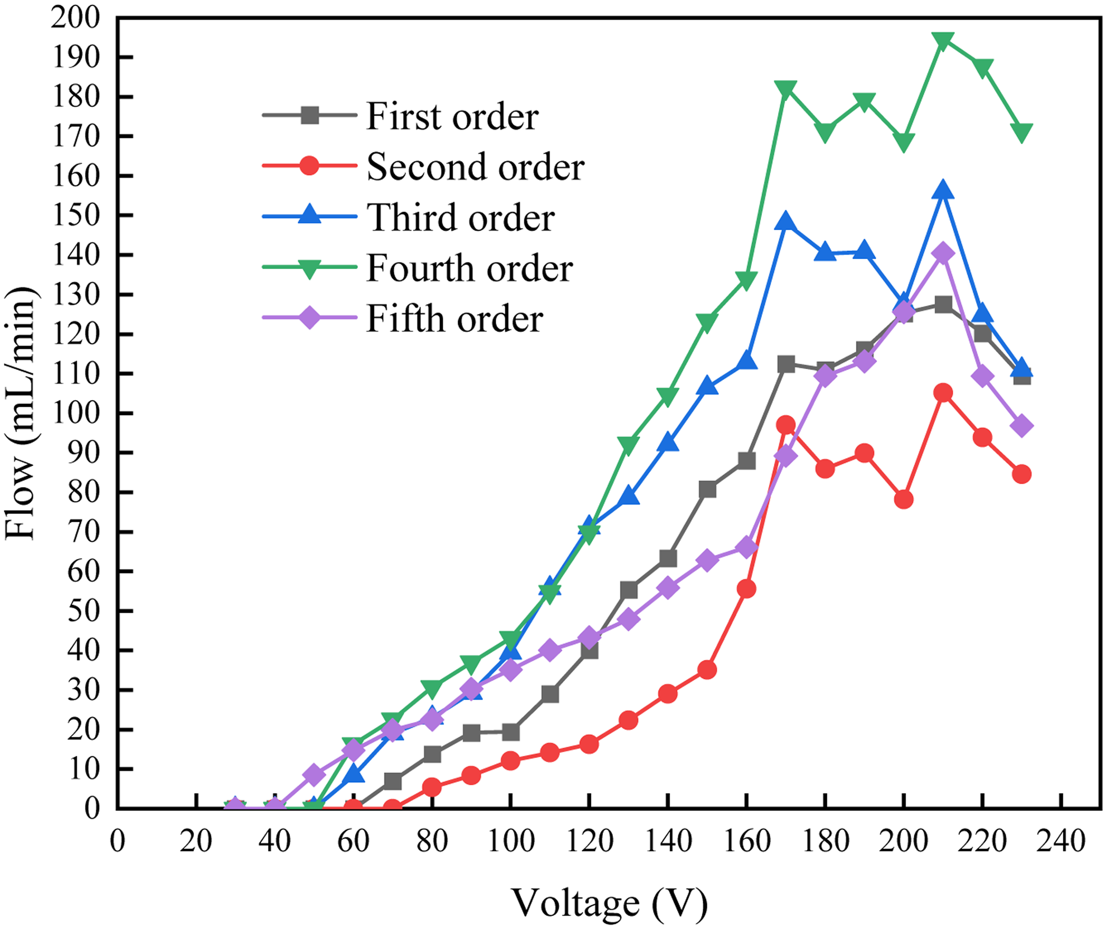
As can be seen from Figure 24, the output flow of the pump shows a multi-peak curve with increasing frequency, with two peaks, the first of which appears at 48 Hz as the maximum output flow, and the second peak has an uneven frequency distribution and one unsatisfactory output flow. When the dune order is 4, the pump output is better. Figure 25 shows the volt-flux curves of various dune order prototypes. In the initial phase of the voltage increase, the output current increases steadily. When the output voltage is less than 170 V, the five-order flux increasing trend is about the same, and the fourth-order structure is replaced by other structures when it reaches the first peak. When the voltage is greater than 170 V, the second wave peak appears in each order structure. The fourth-order piezoelectric pump output is better, and the output is best at 210 V, and the flow rate reaches 194.7 L/min.
Voltage-flow curves of prototypes with different dune orders.
Conclusion
A type of crescent-shaped dune structure with liquid resistance and a valveless piezoelectric pump is presented. The working principle of the pump is described and the flow equation of the pump is established.
The simulation model of the piezoelectric pump was created to check the effectiveness of the crescent-shaped dune structure and the influence of the inclination angle, the radius of the sand wall and the order of the liquid resistance on the output flow characteristics of the valveless piezoelectric pump that was obtained.
The prototype of the valveless piezoelectric pump was made by 3D printing technology, and the flow characteristics of three parameters, tilt angle, sand ridge radius and order, were respectively tested, and the output flow at different drive frequencies and voltages were tested. The experimental results showed that when the inclination angle of the dune is 37.5°, the ridge radius is 6.75 mm, and the structure order is 4, the pump output is the best, namely 194.7 mL/min, which is substantial with the simulation match results.
Only a part of the parameters were optimized and analyzed in this article, and the optimal output of the piezoelectric pump was obtained, as well as the curve radius of the windward slope and the leeward slope in the dune structure and the spacing between the multi-stage resistance fluids, which can be optimized and analyzed experimentally in future studies.
Footnotes
Acknowledgment
This work was funded by the Education Department of Hunan Province of China (22A0034).
Declaration of conflicting interests
The author(s) declared no potential conflicts of interest with respect to the research, authorship, and/or publication of this article.
Funding
The author(s) disclosed receipt of the following financial support for the research, authorship, and/or publication of this article: This work was supported by the Education Department of Hunan Province of China (grant number 22A0034) and Taizhou Science and Technology Plan Project(grant number 23gyb10).
Author biographies
Changxiong Xie holds a PhD in Mechanical Engineering. His area of research is analysis and simulation of fluid dynamics, digital design, and manufacturing technology.
Shuaishuai Zhou is a graduate student majoring in Mechanical Engineering. Her area of research is mechatronics integrated control.
Yong Zhang is a professor in Mechanical Engineering. His area of research is fluid engineering focusing on fluid-structure coupling simulation.
Jianchen Wang is an associate professor of Mechanical Engineering. His research direction is numerical control equipment technology.
Xiaolei Deng is a professor of Mechanical Engineering. His area of research is digital design and manufacturing technology, CNC equipment and automation technology.
Jun Yang holds a PhD in Mechanical Engineering. His area of research is dynamics and control of electromechanical hydraulic systems.