
Abstract
Selective catalytic reduction is the main technology to reduce oxides of nitrogen of diesel exhaust. As an important part of the selective catalytic reduction system, the air-assisted urea dosing system regulates the flow rate by adjusting the pump speed, and the flow rate and its metering accuracy directly affect the efficiency of oxides of nitrogen conversion. A mathematical model coupled with the air-assisted urea dosing system and the suction pipeline was built, and the influences of the discharge pressure, pump speed, suction pipeline length, and diameter on the flow characteristics and metering accuracy of the air-assisted urea dosing system were analyzed. The flow rate and metering accuracy of a prototype of the air-assisted urea dosing system were tested under different conditions on a test rig. Results show that the flow stability and metering accuracy of the prototype elevate with increasing the discharge pressure when the prototype has no overfeeding, and it gets down under any discharge pressure when the prototype occurs overfeeding. The flow stability and metering accuracy of the prototype improve with increasing the pump speed, and increase significantly when the suction pipeline length becomes shorter and the diameter gets larger. The metering accuracy of the prototype can achieve to ±2% by optimizing the suction pipeline parameters. The experimental results prove that the proposed mathematical model is effective.
Keywords
Introduction
In recent years, selective catalytic reduction (SCR) has become the mainstream after-treatment technology to reduce oxides of nitrogen (NOx) emission of diesel exhaust.1–6 The system uses a urea water solution (UWS) as the reductant to convert NOx in the exhaust to N2 and H2O by using a catalyst. 7 The UWS plays a crucial role for NOX conversion,8,9 which is a corrosive liquid that freezes below −11°C and crystallizes easily.10–12 Therefore, the SCR system has strict requirements for the urea dosing system (UDS). As one of the most important components of the SCR system, the performance of the UDS has a direct impact on the efficiency of NOx conversion. The aim of the UDS is to make its flow rate close to the required value. Because of diesel engines work in dynamic operating conditions, the NOX emission and the required value of the UDS are dynamic processes. When the flow rate is less than the required value, the NOX cannot be completely converted. If the flow rate is greater than the required value, NH3 cannot be completely oxidized, that will cause secondary pollution.13,14 So, it is better to make metering accuracy of the UDS up to ±2% under all operating conditions of diesel vehicles.
According to atomization modes, there are two types of the UDS: the air-assisted UDS (AUDS) and non-air-assisted UDS. The AUDS uses compressed air to assist atomization, which has a better atomization effect and a higher efficiency of NOX conversion. So the AUDS is commonly used in the SCR system. In the AUDS, there is a diaphragm pump as the pressure source to delivery UWS, which has high metering accuracy, high reliability, corrosion resistance, and non-leaking. 15 The AUDS mainly realizes variable flow rate by adjusting the pump speed and its metering accuracy depends on the flow stability of the diaphragm pump.
Several studies have been conducted to investigate the metering accuracy of the UDS, and some of them paid more attention to the metering accuracy control strategies. Lin et al. 16 proposed a new method of dynamic flow compensation and dynamic conditions switching to optimize the dynamic accuracy and the dynamic response speed, and the metering accuracy was improved from ±10% to ±4% and became more stable than before. Lee and Park 17 established a three-dimensional numerical model for the analysis of the internal flow characteristics of urea injectors depending on the needle movement for the UDS, and the consequences would be helpful in comparing various data sets for establishing metering accuracy control strategies. Wu et al. 18 introduced the design of the UDS in the SCR system with the versatility and openness to meet use requirements and achieve higher metering accuracy, and the test results indicated the design achieves the intended purpose. Petzold et al. 19 presented a simulation model with the piston motion and the check valve for elevating the high level of metering accuracy of the UDS, which explained a methodology to locate and reduce potential critical flow areas, such as regions with high flow velocities and low static pressure. Meanwhile, he developed a measurement method for the motion of the piston and valve, which verified the accuracy of the simulation model.
Above literatures mainly focused on the metering accuracy control strategies, but the following studies also indicated that the structure parameters of the AUDS had a strong influence on flow characteristics of a fluid power system. Valdés et al. 20 analyzed the flow characteristics of the valve ball by numerical simulation with a cavitation model and experimental test, and the correlation between the measurements and CFD (computational fluid dynamics) predictions is excellent in both cases. Semlitsch et al. 21 performed Large Eddy Simulations in a realistic internal combustion geometry using three different modeling strategies, that is, fixed valve lift and fixed piston, moving piston and fixed valve lift, and moving piston and moving valve, to estimate the energy losses. The results showed that accounting for piston motion and limited valve motion leads to a minor discharge coefficient alteration of about 1%–2%. Kajiware et al. 22 built a full-scale model of a check ball made of acrylic resin, and the flow rate increased in a standard center inflow model at most positions of the check ball. Liu et al. 23 established a mathematical model coupled with compressor, actuator, and hydraulic system to analyze the dynamic performance of suction valve influence by structural and operating parameters, and the maximum displacement of actuator increased with the oil pressure until it is limited by the lift limiter. Wang et al. 24 installed an experimental investigation on the valve dynamics especially the inclining angle and the impact velocity. This experiment measuring method and results could provide useful information for both valve testing and optimization of the valve reliability.
However, few previous works have studied the influences of the operation conditions and suction pipeline parameters on the flow characteristics and metering accuracy for the AUDS using a mathematical model. In this article, a mathematical model coupled with the AUDS and the suction pipeline was built, and the influences of the discharge pressure, pump speed, suction pipeline length, and diameter on the flow characteristics and metering accuracy were analyzed. The flow rate and metering accuracy of a prototype of the AUDS were tested under different conditions on a test rig.
Theoretical analysis
Operating principle
The AUDS is mainly composed of a diaphragm pump, dosing control unit (DCU), pressure and temperature sensors, pressure switch, valves, and so on, which are shown in Figure 1. The diaphragm pump is a core part of the AUDS, which includes a pump shaft, eccentric shaft, connecting rod, diaphragm, suction, and discharge valves. As shown in Figure 1, the rotational motion of an electric motor is turned to the linear motion through the eccentric shaft, bearing, connecting rod, and diaphragm. When the diaphragm deforms from the lower dead-center to the upper dead-center, the volume of the working chamber expands and the inner pressure gradually decreases. At the moment that the suction valve opens and the discharge valve closes, the UWS is drawn into the working chamber. When the diaphragm deforms from the upper dead-center to the lower dead-center, the discharge valve opens and the suction valve closes, and the UWS is discharged from the working chamber.
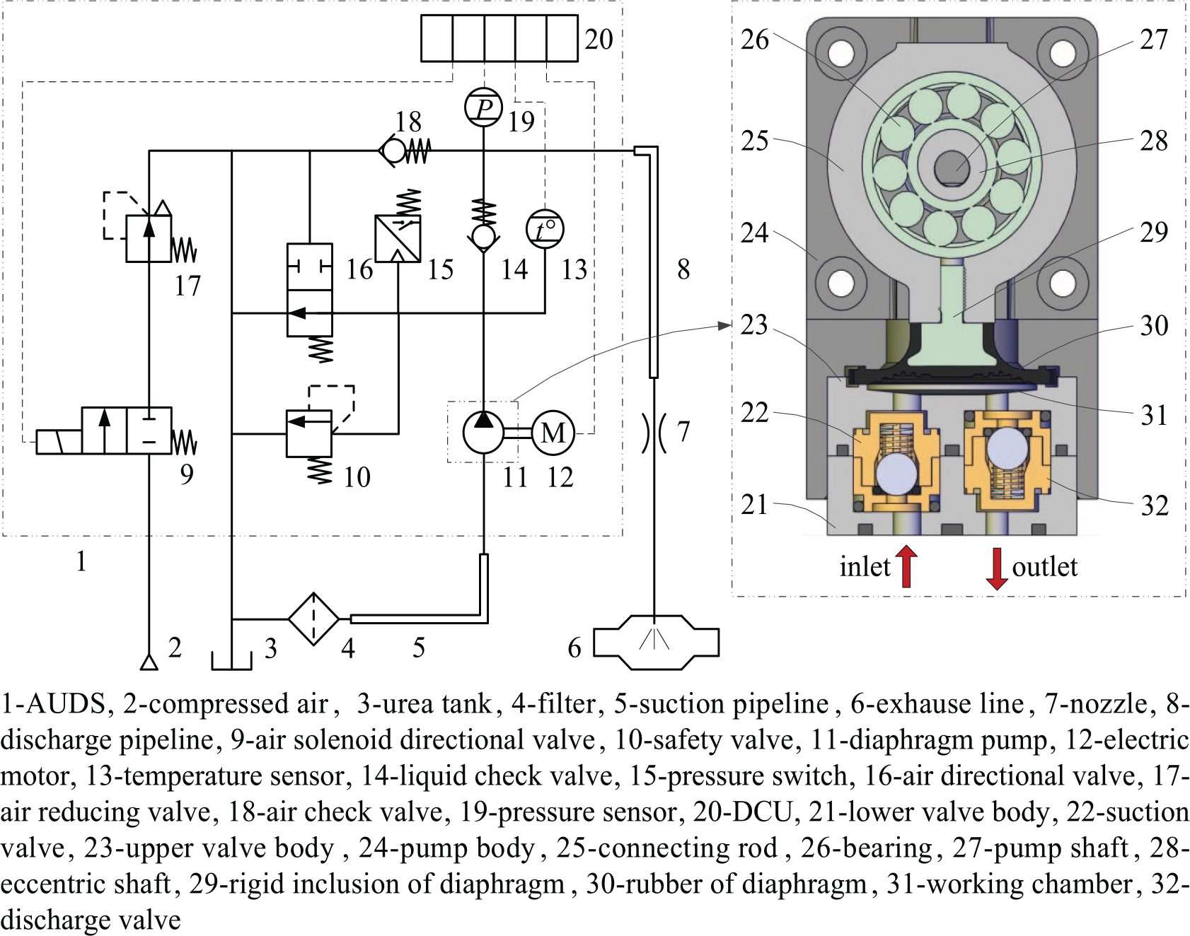
Schematic diagram of the AUDS.
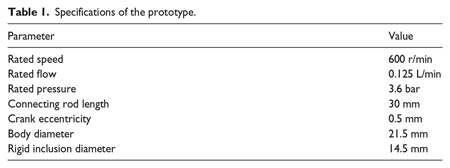
Specifications of the prototype are introduced in Table 1. It is obvious that the AUDS has the following features: high speed, low discharge pressure, small flow rate, long suction pipeline, and so on.
Specifications of the prototype.
Flow characteristics
In order to analyze the flow characteristics of the AUDS, some assumptions and calculation conditions are listed as follows:
The UWS is incompressible.
The pressure inside the working chamber is uniform.
A side of the diaphragm is open to the atmosphere, and the effect of air pressure on the diaphragm is negligible.
The leakage is negligible.
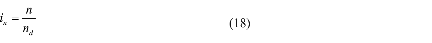
The flow rate of the AUDS is the UWS volume measured at the outlet in unit time, which is less than the theoretical flow since the volume loss. Hence, the flow rate is shown as

The size, motion, and strain of the diaphragm have a great influence on the capacity of the AUDS, and the principle of the diaphragm motion and deformation is analyzed, as shown in Figure 2. The effective diaphragm diameter is limited by the rigid inclusion and body diameters in function of the diaphragm displacement. If the upper dead-center is considered to zero crank angle, the motion of the diaphragm can be expressed as follows


Principle of the diaphragm motion and deformation: (a) Diaphragm motion and (b) diaphragm deformation.
The flow rate due to the diaphragm strain is calculated as

For Figure 2(b), the diaphragm displacement is forced to zero. One of the two chambers is pressurized, and the other is open to the atmosphere. The measurement of the pressure and volume variation in the working chamber leads to
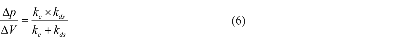
According to equation (6), kds can be calculated, so the theoretical capacity is computed as

The pipeline and valve are equally important to the flow characteristics of the AUDS. The suction pipeline is in line with the flow direction, and the discharge pipeline deviates from the flow direction.
So the suction pipeline has a significant impact on the flow characteristic of the AUDS. Besides, the motion of the valve ball directly determines the flow stability of the AUDS, and the valve ball is driven by the differential pressure between up and down stream of the valve port when the AUDS is operated. The working chamber has a relatively high pressure in the discharge process due to the back pressure, and it produces low negative pressure in the suction process because its volume is small. Therefore, the motion of the suction valve ball is more stable than that of the discharge valve ball. The following is an analysis of the effect of suction pipeline and the suction valve on the flow characteristics of the AUDS. The parameters of the suction pipeline and suction valve of the prototype are listed in Table 2.
Parameters of the suction pipeline and suction valve of the prototype.

The flow velocity of the UWS in the suction pipeline is fluctuation. When the pressure caused by fluid inertia force in the suction pipeline exceeds the discharge pressure of the AUDS, the discharge valve opens in advance or the suction valve closes delayed, and the UWS will outflow automatically. At the moment, the flow rate is greater than the theoretical flow, that is, the volumetric efficiency is over 100%, which are called an overfeeding. The overfeeding seriously affects the performance of the AUDS. According to Bernoulli’s equation, the pressure in the suction pipeline and the working chamber can be described as

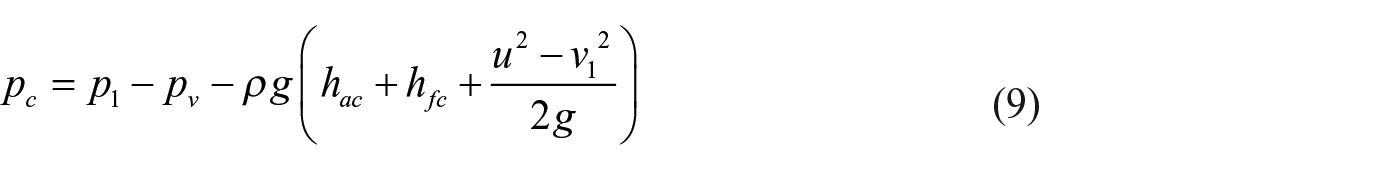
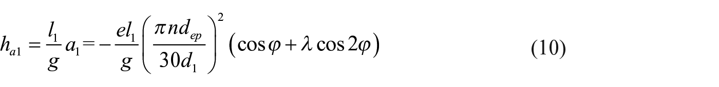
Since there is no resistance elements in the suction pipeline, ps is equal to zero pressure. In addition, hac and hfc are small and negligible compared with ha1. Thus, pc1 is determined by p1, and its variation rule is approximately proportional to ha1. To ensure that the AUDS has no overfeeding, the following conditions have to be met

By equation (11), in suction process of the AUDS, pc is proportional to l1 and n2, and it is inversely proportional to
The suction valve is equivalent to a mass spring damping system and the motion principle of the suction valve ball directly determines the inlet instantaneous flow of the AUDS, which is shown in Figure 3. The suction valve ball is opened only after the differential pressure between up and down stream of the valve port exceeds the opening pressure due to the response lag of the mass spring damping system. As a consequence, the suction valve ball is opened abruptly, and the impulse force causes a sudden change of its velocity. According to Newton’s second law and the actual force acting on the suction valve ball, the equilibrium equation of the valve ball can be described as
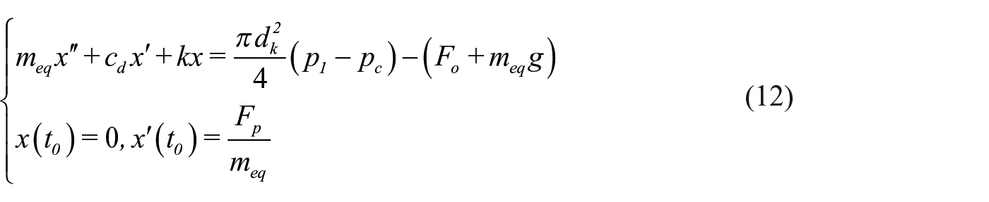
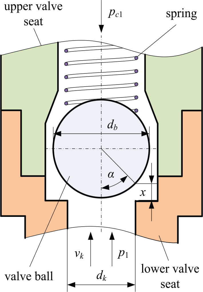
Motion principle of the suction valve ball.
The inlet instantaneous flow of the AUDS is positively correlated with the motion of suction valve ball, which is calculated by the orifice flow formula, that is

The instantaneous flow is the pulsation and unsteady flow, because the motion of the suction valve ball is approximately sinusoidal motion. Moreover, flow stability of the AUDS can be described by the flow pulsation rate and oscillation time of the instantaneous flow. The flow pulsation rate can be expressed as

Metering accuracy
The metering accuracy of the AUDS is that its flow rate can be accurately adjusted to the required value. There is no other item that contains the ability to accurately change flow rate and that gives an indirect indication of the flow value. The various terms related to accuracy are steady-state accuracy, repetitive accuracy, and linearity.
The steady-state accuracy is the relative limit error of the rated flow by a continuous flow measurement under different operating conditions. The repetitive accuracy describes the ability to reproduce a specific flow rate under different operating conditions when the flow value is varied. The linearity is the maximum deviation from the ideal straight line that describes how the flow rate varies, which is expressed as a percentage of the rated flow under different operating conditions. The accuracy of a steady-state, repetitive, and linearity can be expressed as
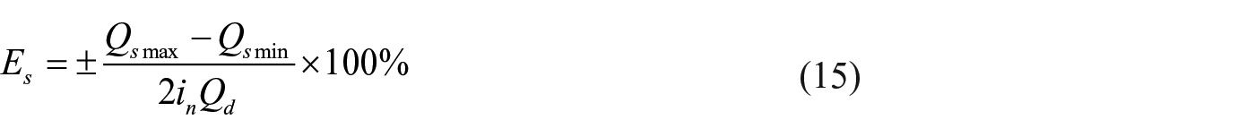


In addition, it is better to make metering accuracy of the AUDS up to ±2% under different operating conditions. Therefore, the metering accuracy is the maximum of the accuracy of a steady-state, repetitive, and linearity, which can be described as

Test system
In order to test the performance of the AUDS prototype, a test rig has been developed and manufactured, which is shown in Figure 4. The AUDS prototype is the model coupled with the AUDS and the suction pipeline. Figure 4 displays a photo of the complete test rig, with the hydraulic system, control system, computer, and so on. A schematic diagram of the test rig is shown in Figure 5. The DCU receives the corresponding pump speed instructions and drives the electric motor, and the AUDS can be operated in different pump speeds. The test rig can match suction pipeline with different length and diameter. The flow rate of the prototype has been measured by weight increasing method.

Test rig for the AUDS.

Schematic diagram of the test rig.
Results and discussion
In this section, the influences of the discharge pressure, pump speed, suction pipeline length, and diameter on the flow characteristics and metering accuracy of the AUDS prototype were studied.
Flow characteristics of the prototype
Under different discharge pressures and pump speeds
Figure 6 provides the flow characteristics of the prototype under different discharge pressures. As the discharge pressure increases, the flow rate reduces at rated pump speed. For zero discharge pressure, the pressure in the discharge pipeline is equal to the opening pressure of the discharge valve. At this moment, pc is greater than po2 in suction process from equation (11). The volumetric efficiency reaches 107.7% and the prototype occurs an overfeeding.
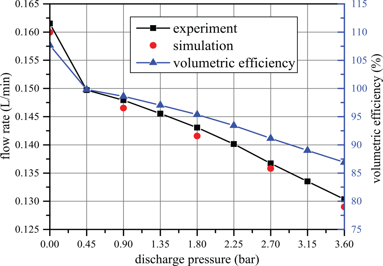
Flow characteristics of the prototype under different discharge pressures (n = 600 r/min, l1 = 1.2 m, d1 = 6 mm).
Figure 7 represents the flow characteristics of the prototype under different pump speeds. For zero discharge pressure, the volumetric efficiency is essentially uncharged when the pump speed ratio is less than 0.75. The prototype occurs an overfeeding when the pump speed ratio is larger than 0.75. For the discharge pressure is 3.6 bar, there is no overfeeding when the pump speed ratio is larger than 0.75, but the volumetric efficiency also abnormally increases. This is because the suction valve closes delay and the flow rate increases when the UWS inertia in the suction pipeline is too large. Thus, if the overfeeding occurs, the volumetric efficiency abnormally increases even though there is no overfeeding with increasing the discharge pressure. The experimental results also show the excellent agreement with the simulation ones.
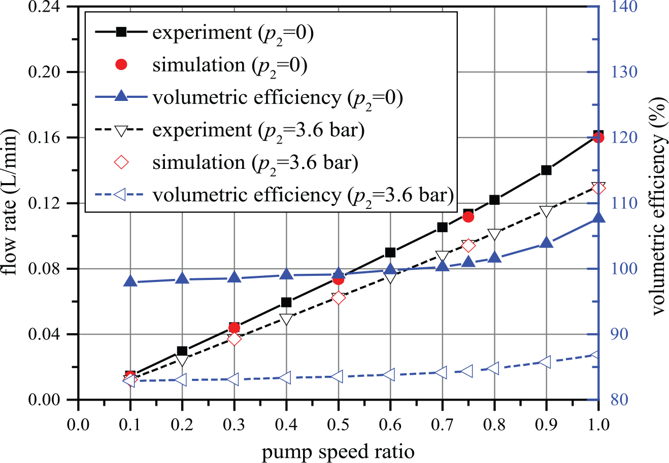
Flow characteristics of the prototype under different pump speeds (l1 = 1.2 m, d1 = 6 mm).
The dynamic responses of the prototype under different discharge pressures are shown in Figure 8. It is assumed that the inlet flow direction is negative and the outlet flow direction is positive. Figure 8(a) indicates the vibration of the suction valve ball is more greatly than that of the discharge valve ball. That is because the UWS inertia in the suction pipeline has a large influence on the motion of the suction valve ball. The opening lag angle of the suction and discharge valves increase by 28.1° and 44.6°, respectively, when the discharge pressure rises from 0 to 3.6 bar. This explains why the volumetric efficiency reduces with increasing the discharge pressure. Figure 8(b) shows the change rule of the instantaneous flow coincident to that of the valve ball lift. For zero discharge pressure, the discharge and suction valves are opened simultaneously at crank angle from 74.9° to 93.6° and 151.9° to 164.1°, respectively. Therefore, the flow stability gets worse with increasing the discharge pressure.

Dynamic responses of the prototype under different discharge pressures (n = 600 r/min, l1 = 1.2 m, d1 = 6 mm): (a) Valve ball lift and (b) instantaneous flow.
Figure 9 shows the instantaneous flow of the prototype when the pump speed ratio is set at 0.1, 0.75, and 1. The flow pulsation rate of the inlet instantaneous flow decreases by 1.1% and the oscillation time is greatly shortened when the pump speed ratio rises from 0.1 to 0.75. The flow pulsation rate increases by 20.1% when the pump speed ratio rises from 0.75 to 1. It also indicates that the flow stability improves with increasing the pump speed, but the overfeeding results in poor flow stability. So the overfeeding of the AUDS should be avoided.

Instantaneous flow of the prototype under different pump speeds (p = 0, l1 = 1.2 m, d1 = 6 mm).
Under different suction pipeline lengths
The suction pipeline length is varied from 0.2 to 2 m, and the other conditions keep the same. Figure 10 represents the flow characteristics of the prototype under different suction pipeline lengths. For zero discharge pressure, the volumetric efficiency is less than 100% when the length is less than 0.8 m, and it is greater than 100% when the length is larger than 0.8 m. The reason is that the UWS inertia in the suction pipeline becomes larger with increasing the length, resulting in the volumetric efficiency over 100%. When the discharge pressure is 3.6 bar, there is no overfeeding if the length is larger than 0.8 m, but the volumetric efficiency also abnormally rises.

Flow characteristics of the prototype under different suction pipeline lengths (n = 600 r/min, d1 = 6 mm).
Figure 11 provides the instantaneous flow of prototype under different suction pipeline lengths. In this figure, the discharge and suction valves are opened simultaneously at crank angle from 115.9° to 127.4° when the length is 0.8 m and crank angle from 100.8° to 205.9° when the length is 2.0 m, respectively. The flow pulsation rate of the inlet instantaneous flow increases by 9.7%, while the suction pipeline length increases from 0.2 to 0.8 m. The flow pulsation rate decreases by 1.4% and the average flow increases by 32.4% when the length becomes long from 0.8 to 2.0 m. In addition, the oscillation time of the instantaneous flow is longer with increasing the pump speed ratio. Hence, the flow stability decreases with increasing the suction pipeline length.
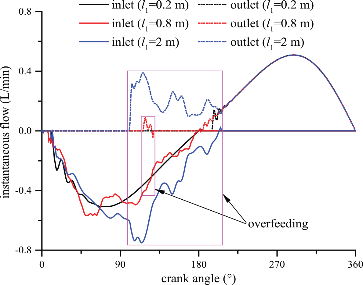
Instantaneous flow of the prototype under different suction pipeline lengths (n = 600 r/min, p2 = 0, d1 = 6 mm).
Under different suction pipeline diameters
The flow characteristics of the prototype under different suction pipeline diameters are shown in Figure 12. For zero discharge pressure, the volumetric efficiency is less than 100% when the diameter is larger than 8 mm, and it is greater than 100% when the diameter is less than 8 mm. This is because that the UWS inertia in suction pipeline becomes larger with increasing the diameter, resulting in the volumetric efficiency over 100%. When the discharge pressure is 3.6 bar, there is no overfeeding with decreasing the diameter, but the volumetric efficiency also abnormally increases when the diameter is less than 8 mm.

Flow characteristics of the prototype under different suction pipeline diameters (n = 600 r/min, l1 = 1.2 m).
Figure 13 shows the instantaneous flow of the prototype under different suction pipeline diameters. The discharge and suction valves are opened simultaneously at crank angle from 123.8° to 134.6° when the diameter is 8 mm and crank angle from 102.9° to 234.7° when the diameter is 4 mm, respectively. The flow pulsation rate of the inlet instantaneous flow decreases by 9.9%, while the diameter becomes large from 8 to 12 mm. The flow pulsation rate decreases by 7.9% and the average flow increases by 54.1% when the diameter decreases from 8 to 4 mm. Thus, the flow stability improves with increasing the suction pipeline diameter.

Instantaneous flow of the prototype under different suction pipeline diameters (n = 600 r/min, p2 = 0, l1 = 1.2 m).
Metering accuracy of the prototype
The metering accuracy is an important index of the AUDS performance, and it is calculated through equations (15)–(17) and (19). The steady-state accuracy is calculated by three measurement results, and the repetitive accuracy and linearity are 10 measurement results. The metering accuracy of the prototype is determined by its flow stability, and it is improved with the increase of the flow stability.
Under different discharge pressures and pump speeds
Figure 14 represents the metering accuracy of the prototype under different discharge pressures and pump speeds. For zero discharge pressure, the steady-state and repetitive accuracy, and linearity are ±2.81%, ±3.88%, and ±7.67%, respectively. The accuracy improved slowly with increasing the pump speed, but it shows a rapid decrease while the prototype occurs an overfeeding. When the discharge pressure increases from 0 to 3.6 bar, the steady-state and repetitive accuracy get worse when the pump speed ratio is less than 0.75, but it becomes well when the pump speed ratio is larger than 0.75. The flow pulsation rate increases with increasing the opening lag angle of the suction and discharge valves. When the discharge pressure is 3.6 bar, the metering accuracy is ±4.28%. It also indicates that the metering accuracy of the prototype is bad under different operating conditions and the change of the discharge pressure and pump speed has a great impact on the metering accuracy.

Metering accuracy of the prototype under different discharge pressures and pump speeds (l1 = 1.2 m, d1 = 6 mm): (a) Steady-state accuracy, (b) repetitive accuracy, and (c) linearity.
Under different suction pipeline lengths
The suction pipeline length directly determines the liquid inertia in the suction pipeline, and consequently, it influences the motion of the suction valve and the inlet instantaneous flow. Figure 15 provides the metering accuracy of the prototype under different suction pipeline lengths. When the length is changed from 1.2 to 0.2 m, the steady-state and repetitive accuracy and linearity are improved to ±1.12%, ±1.65%, and ±1.63%, respectively. On the contrary, the accuracy experiences a severe reduction when the length increases to 2 m. As a result, the metering accuracy of the prototype is improved as the suction pipeline gets short.

Metering accuracy of the prototype under different suction pipeline lengths (p2 = 3.6 bar, d1 = 6 mm): (a) Steady-state accuracy, (b) repetitive accuracy, and (c) linearity.
Under different suction pipeline diameters
The suction pipeline diameter also influences the motion of the suction valve and the inlet instantaneous flow. When the diameter is changed from 6 to 12 mm, the steady-state and repetitive accuracy, and linearity are ±1.26%, ±1.92%, and ±1.83% respectively, which experience a great improvement. When the diameter decreases to 4 mm, metering accuracy dramatically gets bad. Therefore, the metering accuracy of the prototype becomes well as the suction pipeline diameter increases. The detailed values are displayed in Figure 16.

Metering accuracy of the prototype under different suction pipeline diameters (p2 = 3.6 bar, l1 = 1.2 m): (a) Steady-state accuracy, (b) repetitive accuracy, and (c) linearity.
Conclusion
In this study, a mathematical model coupled with the AUDS and the suction pipeline was built, and the influences of the discharge pressure, pump speed, suction piping length, and diameter on the flow characteristics and metering accuracy of the AUDS were analyzed. The flow rate and metering accuracy of the AUDS prototype were tested under different conditions on a test rig. The conclusions can be summarized as follows:
The change of the discharge pressure and pump speed has a large impact on the flow characteristics and metering accuracy of the AUDS. If the AUDS has no overfeeding, the flow stability and metering accuracy need to be improved with increasing the pump speed or decreasing the discharge pressure. The overfeeding results in poor flow stability and metering accuracy, and it should be avoided.
The UWS inertia in the suction pipeline has a great influence on the flow characteristics and metering accuracy of the AUDS. The metering accuracy of the prototype increases from ±4.28% to ±1.65% when the suction pipeline length increases from 1.2 to 0.2 m. The accuracy increases from ±4.28% to ±1.95% when the suction piping diameter becomes large from 6 to 12 mm. The accuracy could reach ±2% and meet the use requirements by changing the suction pipeline parameters.
The test results show the mathematical model coupled with the AUDS and the suction pipeline is reasonable and the variation trend of the metering accuracy is consistent with the flow stability of the AUDS.
Footnotes
Appendix 1
Declaration of conflicting interests
The author(s) declared no potential conflicts of interest with respect to the research, authorship, and/or publication of this article.
Funding
The authors would like to thank the financial support from the National Natural Science Foundation of China under Grant 51575200 and the National Key Research and Development Program of China under Grant 2016YFC0300600.