
Abstract
To study the effects of the performance of different types of impeller on the vortex pump, orthogonal test design, which is carried out by combining experimental test and numerical calculation, is adopted to optimize the type of design structure for the impeller in vortex pump. To find out the folding blade angle, the position of the folding point in the whole blade, and whether to wedge folding blade, an orthogonal test scheme with three factors and two levels is designed. A numerical simulation test is conducted for each scheme by analyzing the performance curve of orthogonal test plan to find the optimal performance of the program and analyzing the test data of each scheme to obtain the primary and secondary orders of the impact performance in the angle of folding blades of the vortex pump, the position of folding point of blades, and the wedge shape of blades. The results show that the optical blade type combination is the blade angle R30F60, the folding point is at 2/3 of the whole blade, and the blade does not adopt radial wedge. The optimal combination scheme is 36% higher than the design value at the rated flow head, the efficiency is 18.75% higher than the design value, the high-efficiency zone of the vortex pump is wider, and the performance meets the design requirements. Through orthogonal experimental design, the design cycle of vortex pump can be shortened effectively, the design level of vortex pump can be improved, and the hydraulic model with superior performance can be obtained.
Introduction
As a kind of impurity pump, the vortex pump (also called free-flow pump) is especially suitable for pumping liquids containing large particles due to the structural characteristics of the cavity. With the continuous development of industry and agriculture, the vortex pump has been widely used in sewage treatment, slurry, large-particle medium transportation, and other fields; its structure is shown in Figure 1. 1

Structure of vortex pump: 1, inlet section; 2, no blade cavity; 3, shrink chamber wall; 4, impeller; and 5, axle.
In 1954, the Western Machine Company developed the first WEMCO vortex pump. In 1956, the Swedish company Sterbery-Flygt developed a vortex sewage submersible 2 pump. In 1968, Rutschi, a scholar in West Germany, published the first document on vortex 3 pumps. Aiming at the flow characteristics and flow mechanism of the vortex pump, in the 1980s, Schivley, Oraba Hideki, and Hideki Ohba established the flow model on the basis of previous4–6 experiments. Research on vortex pump started late in China. Shijiazhuang Pump Works tried and manufactured a vortex pump for cis-polybutadiene rubber in the mid-1960s. In 1979, Zhencheng et al. 7 carried out an experimental study of 6J35-type vortex pump. Later, numerous scientific researchers continued to explore and improve the research results of modern vortex pump.
At present, model test is the most accurate method to optimize the design of vortex pump in domestic and overseas market. In the process of optimization, it is necessary to model test the combination scheme of multiple factors, which is time-consuming. Yi et al. 8 deduced the least-squares liberation program of empirical coefficients of centrifugal slurry pump and vortex pump by combining test, analysis, and statistics. Zheng and Cheng 9 studied the influence of the structural parameters of the vortex pump on the pump performance. Quan et al. 10 tested the solid–liquid two-phase flow pump by particle image velocimetry (PIV) test and summarized the energy conversion law of the solid–liquid two-phase flow pump. Weidong et al. 11 conducted further research on the internal flow characteristics of the vortex 12 pump.
The vortex pump works on the fluid through impeller rotation, which makes the fluid in the vaneless cavity in front of the impeller form run-through flow and circulating flow. However, research on the influence of impeller configuration on the performance of vortex pump is still insufficient. In numerical calculation and experiment, only one structural type is changed at a time, while the other structural types are fixed. The influence of changing two or more structural types on the performance of vortex pump is seldom considered. Orthogonal test method is widely used in the optimization design of pumps as an efficient method to deal with multifactor optimization design, which effectively solves the problem of too long model test13–16 cycle. The orthogonal test was carried out to analyze the influence of different impeller configurations on the performance of the vortex pump.
Structural design of vortex pump
Impeller design
The hydraulic optimization design of the main flow passage parts of the vortex pump, including deflection angle of the impeller blade, point position, and wedge shape, is carried out. The main design parameters of the horizontal 150 WX-200-20 vortex pump are as follows: rated flow Q = 200 m3/h, rated head H = 20 m, rated speed n = 1450 r/min, specific speed ns = 132, rated efficiency η = 50%, and shaft power P = 21.952 kW. The hydraulic parameters of the vortex pump that are used to obtain the geometric parameters of the impeller are shown in Table 1.
Geometrical parameters of the impeller.

Volute design
According to the hydraulic design of the front impeller, circular volute is selected. Through the hydraulic design, the schematic diagram of the structural design is shown in Figure 2.

Structural design of the vortex pump.
The structural design of the vortex pump is shown in Figure 2. The volute of the geometric parameters of the vortex pump is obtained, as shown in Table 2.
Volute of the geometric parameters.

Orthogonal experimental design
Selection of design parameters
The analysis process of the orthogonal test design includes five basic6,17–21 steps: determining the number of test factors and the level of each factor, designing the appropriate orthogonal table, listing the test scheme and test results, carrying out range analysis and regression analysis on the results of orthogonal test design, and determining the optimal or better combination of factors. In this article, three factors are introduced to optimize the hydraulic performance of a vortex pump: the angle of folded blade, the position of folded blade, and the wedge type of folded blade. Each factor takes two levels. According to the principle of orthogonal method, three factors and two levels are selected to calculate the factor-level table, and the three different factors are represented by A, B, and C. The horizontal table and head design are shown in Table 3.
Factor standard.

In Table 3, A1 represents the impeller with a folded blade angle of R30F30 and A2 represents the impeller with a folded blade angle of R30F60; B1 represents the impeller with a breakpoint of 2/3 of the blade length and B2 represents the impeller with a breakpoint of 3/4 of the blade length; and C1 represents the impeller with a radial wedge for the blade configuration and C2 represents an impeller with no wedged blade structure.
Among them, the folding blade type is shown in Figure 3. The breakpoint starts from the top of the blade and takes the breakpoint at 1/3 and 1/4 of the blade length. The angle between the blade profile and the y-axis is marked as the inclination angle of the first section. If the deflection direction of the blade profile is the same as the rotation direction, then the angle of the blade profile is F1 and the right deviation angle of the blade is R1.
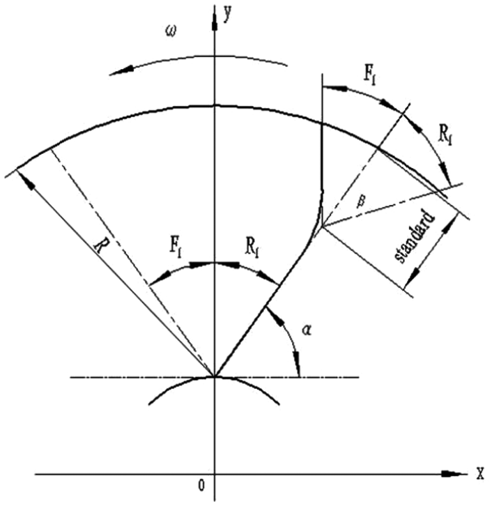
Structure type of blade.
Scheme of orthogonal design
Because the impeller parameters of the selected vortex pump are three, and to meet different conditions (seven kinds) of simulation test, the selection of a more appropriate orthogonal table is particularly important. The L4(2)3 orthogonal table is selected through the actual situation of the vortex pump. Four configuration schemes of Table 4 can be obtained from the orthogonal table, factor-level table, and table head design.
Configuration scheme of the model structure.

To improve the efficiency of the vortex pump, the concept of the impeller structure type of the vortex pump was put forward. The different structure types of the control impeller were selected, and the optimal matching relationship of the impeller structure type was obtained based on the orthogonal test method.
Model establishment
The vortex pump model takes 10 blades as an example. Pro/E model is used in the flow domain of the vortex pump. The model is meshed by ANSYS-ICEM. The mesh is a structured hexahedron mesh. The mesh number of the vortex pump model is about 3 million. The mesh generated at the end of the model is shown in Figure 4. Scheme 1 is a 2R/3 breakpoint wedge R30F30 blade, scheme 2 is a 3R/4 breakpoint wedge R30F60 blade, scheme 3 is a 2R/3 breakpoint normal R30F60 blade, and scheme 4 is a 3R/4 breakpoint normal R30F30 blade.
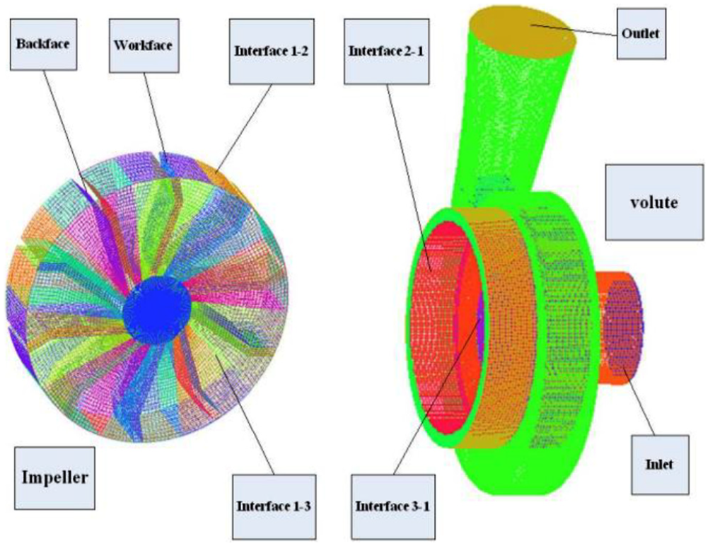
Compute domain and grids.
Numerical simulation method
Three-dimensional steady Reynolds time–averaged Navier–Stokes equation and renormalization group (RNG) k–ε equation are used to solve the model4,22–27; mass inlet condition is adopted for pump inlet; dynamic and static double reference system is used to deal with the flow movement in the impeller and volute; and the rotating coordinate system is adopted for impeller passage area, and the rotating speed is 1450 r/min. The hydraulic diameter is 130 mm, the outlet boundary is set as free outflow, and the flow passage area of the volute adopts a stationary coordinate system.28–38 The internal flow of a vortex pump considers that the rotating flow field rotating around a fixed rotating shaft at a constant angular velocity is a complex three-dimensional incompressible turbulent39–48 flow.
Analysis of numerical simulation results
Performance change of orthogonal test
Each group of test schemes is tested, and the head and efficiency data of rated flow point of test schemes 1–4 are obtained, as shown in Table 5.
Rated flow test results.

When the flow rate is from 0.2Qe to 1.4Qe, the performance curves of H, efficiency η, and shaft power P of the vortex pump are shown in Figures 5–7.

Lift performance (Q–H).

Efficiency performance (Q–η).

Power performance (Q–P).
For Q–H lift performance, the overall Q–H lift performance shows a downward trend under the four schemes, as shown in Figure 5. In scheme 1, the head at the rated flow point is 29.3% higher than the design value of 20 m, and in schemes 2–4, it is 26.35%, 36%, and 17.8% higher, respectively. In scheme 3, the lift performance curve is the best and the impeller performs the most powerful.
For Q–η efficiency performance, schemes 1 and 3 show a slow drop after the maximum efficiency point and a wider efficiency range; the efficiency ratios at rated flow points exceed 18.18% and 18.75%; schemes 2 and 4 show a narrower efficiency range; and the efficiency ratios at rated flow points exceed 18.53% and 14.99%. The best choice is the model of scheme 3 (Figure 6).
For Q–P power performance, the shaft power trend of the four schemes increases with the flow rate, which accords with the actual operation law of the vortex pump, as shown in Figure 7. Analyzing the performance of the four schemes, we can see that the design requirements can be achieved, and scheme 3 is the best.
Through analysis, it is found that the angle change has the greatest impact on the efficiency and head of the whole machine. With the increase in the angle, the head and efficiency of the pump increase accordingly.
Flow field analysis of vortex pump
Under design conditions, the flow field and turbulent kinetic energy are obtained in the vortex pump under four schemes by using orthogonal experimental numerical simulation, as shown in Figures 8 and 9.
Streamline diagrams of the four schemes show that the streamline patterns of schemes 1, 2, and 4 are similar under the design conditions. Scheme 3 has the fewest vortices. In addition to forming a large number of vortices in the circulating flow region, a large number of vortices are formed in the run-through flow region of the impeller, resulting in a loss of energy. Therefore, from the point of view of vortices formed by streamlines, scheme 3 is the best one.
From the turbulent kinetic energy diagram in Figure 9, it can be concluded that scheme 3 has the best design performance. The turbulent kinetic energy distribution in the retractable box is not only very uniform but also symmetrical about the axis line, so it can be judged that the internal flow characteristics of scheme 3 are the best of the four schemes, followed by scheme 2, scheme 1, and scheme 4. The turbulent kinetic energies of the latter three schemes are basically similar. They all form strong and unstable turbulent kinetic energy in the retracting box of the impeller. Their turbulent kinetic energy symmetry is also poor, so the loss may be relatively serious.

Streamline diagrams of four schemes.

Turbulent kinetic energy of four schemes.
With the increase in the deflection angle of the blade breakpoint from 30° to 60°, it is observed from Figure 8 that the vortices generated by the vortex pump decrease accordingly. From Figure 9, it is observed that the turbulent kinetic energy vane decreases and the overall performance of the counter-vortex pump gets better. When the blade breakpoint position increases from 2R/3 to 3R/4, the vortices generated by the vortex pump are observed in Figure 8. It is observed from Figure 9 that the turbulent kinetic energy becomes larger, which is not conducive to the optimization of the overall performance. After thinning the radial thickness of the blade of the vortex pump, it is observed from Figures 8 and 9 that more vortices and larger turbulent kinetic energy are applied to the vortex pump, resulting in energy loss.
By comparing and analyzing the performance of external characteristics and the flow changes of internal flow field, it is found that the results of external characteristic analysis and internal flow field analysis are in good agreement, and the order of performance of test schemes 1–4 is scheme 3, scheme 2, scheme 1, and scheme 4.
The difference in the performance of the vortex pump is mainly caused by the following reasons:
The impeller with wedge blade can theoretically reduce energy loss and improve the flow state in the vortex pump, but it is not so in the orthogonal test. The performance of schemes 2 and 3 is better than that of schemes 1 and 4. It is shown that when the radial wedge structure is adopted, the vortex pump efficiency will be reduced because of the strong vortex at the leading edge of the blade due to the action of circulating flow, which reduces the energy conversion capacity of the vortex pump.
The performance curves of R30F30 blade type and R30F60 wedge blade type at breakpoint 2/3 and R30F60 blade type at breakpoint 3/4 are basically the same, but the head and efficiency of R30F30 vortex pump at breakpoint 2/3 are higher than those of R30F60 vortex pump at breakpoint 3/4 before the rated flow point and after the rated flow point. On the contrary, this is due to the matching relationship between the blade angle and the location of the broken points.
Through the analysis of impeller plane streamline and turbulent flow energy, it is found that the performance of scheme 3 is the best. Therefore, the three-dimensional streamline of scheme 3 is selected to explore the flow law of the vortex pump. Through the observation and analysis of the three-dimensional streamline of scheme 3 of Figure 10, it can be concluded that the flow state of the streamline in the impeller is chaotic, resulting in the generation of a large number of vortices; the streamline trajectory in the volute vaneless chamber is smoother; and the pressure in the impeller is small and too high in the vaneless chamber of volute.

Streamline of scheme 3. (a) streamline of integral, (b) streamline of impeller, and (c) streamline of volute.
Range analysis
The data of the orthogonal test scheme at the highest efficiency point are shown in Table 6.
The highest efficiency point test results.
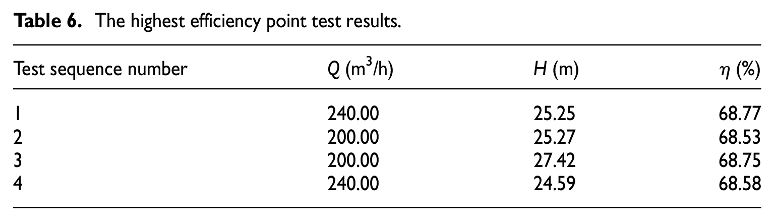
From Table 6, it can be concluded that the highest efficiency point of schemes 2 and 3 is in good agreement with the design condition at rated condition. The highest efficiency point of schemes 1 and 4 is biased toward large flow condition, but the head of the maximum efficiency point is lower than schemes 1 and 2.
Table 7 is the range analysis table for the maximum efficiency point, lift, and efficiency. In this test, the higher the flow rate and head and efficiency index of the highest efficiency point, the better the performance of the vortex pump, so the optimal combination should select the largest level combination of each factor.
Flow and head analysis at the highest efficiency point.

According to the magnitude of the range, it can be judged that the primary and secondary orders of the factors affecting the maximum efficiency point flow are blade angle type, blade breakpoint location, and whether the blade adopts wedge shape or not. According to the value of the index, the best scheme of the highest efficiency point flow is to take A1, B1/B2, and C1/C2 levels for blade angle, breaking point position, and wedge shape, respectively. The best scheme of the highest efficiency point lift is to choose A2, B1, and C2 levels for the blade angle, the position of the breaking point, and the wedge shape, respectively. The best scheme of the highest efficiency point is to choose A1, B1, and C2 for the blade angle, the position of the breaking point, and the wedge shape, respectively. Through the comprehensive comparison of the optimal conditions of each index, the optimum combination of parameters on the hydrodynamic performance index of the vortex pump is obtained: the blade angle type is R30F60, the breakpoint position is at 2/3 of the blade, and the blade without wedge is adopted.
Test and research of vortex pump
Test plan and reliability verification
First, experiment and numerical calculation are carried out on the 2/3R30F60 folded blade. The impeller model and the test model are shown in Figure 11. The schematic diagram (a) and the test diagram (b) of the test device are shown in Figure 12. Before the test, we first controlled the pipeline connection and electrical circuit connection system of the open-type testbed of the pump at the Laboratory of Lanzhou University of Technology and checked whether the measuring instruments and tools were normal to achieve the safety test. In the test process, we used the frequency converter to adjust the speed of the motor from small to large to achieve rotation and also adjust the flow rate of the vortex pump, so as to observe the law of flow through experiments.
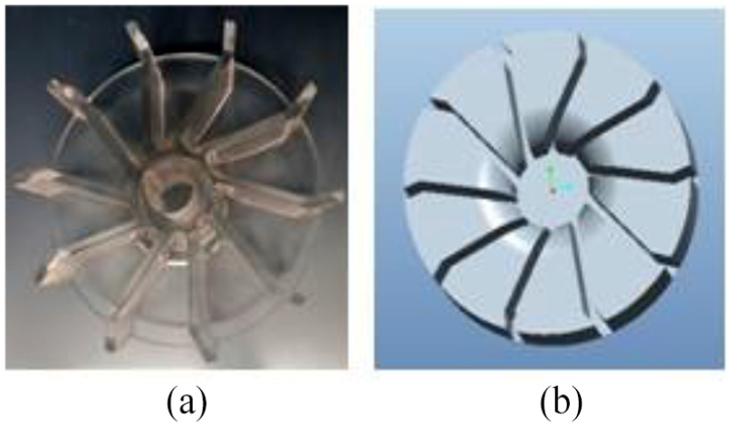
Type 2/3 R30F60 test impeller: (a) test model and (b) calculation model.

Performance test bench for vortex pump: (a) schematic diagram of test device and (b) test device test plan.
Second, the measured data are compared with the calculated data, and the calculated data are tested by the test data. Numerical simulation and experimental data are used to evaluate the orthogonal experimental design.
Comparison between test results and simulation results
Experiments and numerical calculations were carried out with 2/3R30F60 folded blades, and the external performance curves of the 2/3R30F60 folded blade vortex pump were obtained as shown in Figure 13.
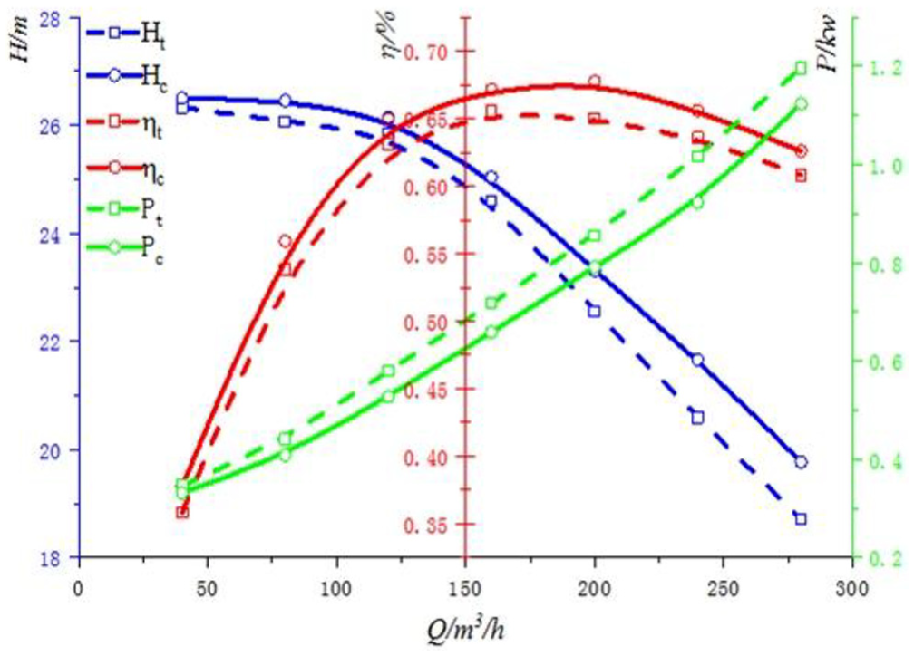
Test and numerical performance.
Analysis of Figure 13 shows that there are errors between test head Ht and numerical simulation head Hc, test efficiency ηt and numerical simulation efficiency ηc, and test shaft power Pt and numerical simulation shaft power Pc data of the whole pump as the flow rate of the vortex pump changes from small to large. The average errors are 2.27%, 5.26%, and 5.94%, respectively. The error of the performance curve from the test data and of the curve from the numerical simulation data is less than 6%. The test results show that the numerical method is reliable for the pump research.
Analysis of internal flow field by test
On the open testbed of vortex pump, the test of vortex pump was carried out. In the testing process, we use the left side lighting, the inlet side, and the right side photography and use high-speed camera to photograph the flow state and the evolution process of the vortices in the vortex pump. Under design conditions, the flow state of the test vortex pump is shown in Figure 14.
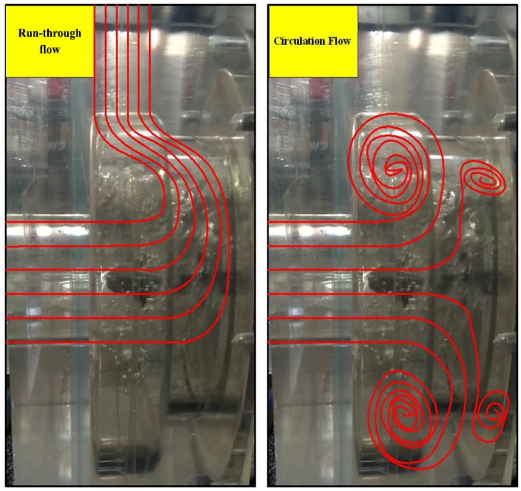
Internal flow structure of the vortex pump.
The main flow pattern of the vortex pump is composed of circulating flow in the vaneless chamber and run-through flow in the retractable chamber. Through observation and analysis, we can see that the circulation flow mainly plays the role of generating vortices and supplementing run-through flow in the vaneless cavity, while run-through flow mainly transmits low-energy fluid through the transmission of impeller energy. Therefore, the circulating flow and run-through flow of the vortex pump are complementary to each other.
Conclusion
In this article, the orthogonal test method is used to replace the full-scale test with the combination of experimental test and numerical calculation. It can not only reduce the number of tests but also ensure that the optimal combination scheme can be obtained quickly, which greatly shortens the test period. Through the orthogonal experimental design method, the following conclusions are obtained:
The main and secondary factors affecting the flow rate at the highest efficiency point of the vortex pump in the test are blade angle type, blade breakpoint position, and whether the blade is wedge-shaped; the primary and secondary factors affecting the lift are blade angle type, blade breakpoint position, and whether the blade is wedge-shaped; and the primary and secondary factors affecting the efficiency are, in turn, position of the blade, the angle of the blade, and the wedge of the blade.
Through the range analysis of the test results, the optimum combination is obtained: the blade angle is R30F60, the breaking point is at 2/3 of the blade, and the wedgeless blade is adopted.
There is an optimum matching problem among the angle type of the folding blade, the position of the folding point, and whether the wedge is used in the design of the vortex pump. The relationship among the three should be considered comprehensively in the design of the vortex pump.
Footnotes
Appendix 1
Declaration of conflicting interests
The author(s) declared no potential conflicts of interest with respect to the research, authorship, and/or publication of this article.
Funding
The author(s) disclosed receipt of the following financial support for the research, authorship, and/or publication of this article: This work was supported by the National Natural Science Foundation of China (NSFC) (51609113), the China Postdoctoral Science Foundation (2018M633651XB), and the Natural Science Foundation of Gansu (2017GS10829).